Distech Controls ECLYPSE User manual

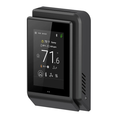
ECLYPSE Connected Thermostat
Product Description
The ECLYPSE Connected Thermostat (ECY-STAT) is geared towards new or existing rooftop unit, heatpump unit, fancoil unit and other zone control ap-
plications. It features a touchscreen interface, multiple connectivity options (both wired IP and Wi-Fi) for system communication, and
Bluetooth
® low en-
ergy (BLE) for mobile connectivity.
General Installation Requirements
For proper installation and subsequent operation of the device, pay special attention to the following recommendations:
£Allow for proper clearance around the device’s enclosure and wiring terminals to provide easy access for hardware configuration and maintenance.
£Orient the device with the ventilation slots towards the top to permit proper heat dissipation.
£The device is designed to operate under the following environmental conditions:
– Operating temperature from 32°F to 104°F (0°C to 40°C)
– Storage temperature from -4°F to 122°F (-20°C to 50°C)
– Relative humidity from 0% to 90%, non-condensing.
£Upon unpacking, inspect the contents of the carton for shipping damages. Do not install a damaged device.
£Ensure proper ventilation of the device and avoid areas where corroding, deteriorating or explosive vapors, fumes or gases may be present.
£Do not install the device in a location with direct airflow to ensure correct temperature regulation.
£If the device is used and/or installed in a manner not specified by Distech Controls, the functionality and the protection provided by the device may
be impaired.
£SELV (Separated Extra Low Voltage) inputs/outputs must be connected to other SELV equipment inputs/outputs.
Any type of modification to any Distech Controls product will void the product’s warranty
Take reasonable precautions to prevent electrostatic discharge to the device when installing, servicing or during operation. Discharge
accumulated static electricity by touching one’s hand to a well-grounded object before working with the device.
General Wiring Recommendations
£Comply with all network and power supply guidelines outlined in the Network Guide.
£Use the screws, wall anchors, and wire nuts included for wall mounting and wiring.
£All wiring must comply with electrical wiring diagrams as well as national and local electrical codes.
£For an easier installation, a flat style Cat5e cable with a low profile connector is recommended. See Distech Controls Field Device product offerings
for more information.
Installation Guide

2 / 17
£To connect the wiring to a device, use the terminal connectors. Use a small flat screwdriver to tighten the terminal connector screws once the wires
have been inserted (strip length: 0.25’’ (6mm), maximum tightening torque 0,4 Nm (3.45 in-lb)).
£Always use unshielded cabling with a minimum Category 5 (CAT5) cable for ethernet communications.
£Keep wiring separate according to their function and purpose to avoid any ambient noise transmission to other wires. Use strapping to keep these
wires separated. For example, keep power, hazardous voltage, SELV, PELV, network, and input wiring separate from each other.
£Do not connect the universal inputs, analog/digital outputs or common terminals to earth or chassis ground (unless stated otherwise).
£Keep input and output wiring in conduits, trays or close to the building frame if possible.
£When connecting one wire to a controller’s terminal block clamping cage (pole), the wire must be between 22 and 16 gauge (0.33 and 1.3mm2
cross-sectional area). When connecting two wires to a controller’s terminal block clamping cage, both wires must be the same thickness, both wires
must be between 22 and 18 gauge (0.33 and 0.82mm2 cross-sectional area), and both wires must be the same type (solid or stranded). Twist the
wires together and insert them into the controller’s terminal block clamping cage. For any other wiring combination (mixed wire thickness, mixed
solid and stranded conductors, more than three wires, wire thickness is out of range), twist the wires together and use a wire nut and a pig tail to
connect to the controller’s terminal block connector as show below.
All wiring recommendations must be followed as incorrect wiring, or a short circuit can permanently damage the device.
Controller
Wire Nuts
Terminal Block
Connector
Wire Connections
Pigtails
Figure1: Using a Wire Nut and Pigtail to Wire the Controller
Dimensions
Figure2: ECY-STAT Dimensions

3 / 17
Mounting Instructions
The ECY-STAT has been specially designed for easy installation. However, certain conditions apply when choosing a suitable location for the device:
£Install the device in a location of average temperature and approximately 1.5 m (5 ft) above the floor
£The device should be installed approximately 15cm (6”) from a corner to provide sufficient access to the faceplate release tabs.
£The device should not be installed on an exterior wall.
£The device should not be installed near a heat source.
£The device should not be installed near an air discharge grill.
£The device should not be installed in a place where it can be affected by the sun or direct air currents.
£Install the device in an area that provides proper device ventilation. Nothing must restrain air circulation to the device.
The ECY-STAT has not been designed for outdoor use.
Mounting hardware is provided with the device for installation on drywall or on an electrical junction box.
ECY-STAT Disassembly
Table1:
ECY-STAT disassembly
Electrical Junction Box Installation Procedure
The ECY-STAT can be mounted in most American, European or Asian style electrical junction box using screws.
1. Remove the front cover of the device:
– Remove the security screw
– Using an appropriately sized tool, press in the release tab on the side of the device and pull the front cover out from the bottom.
2. Pull all cables 15cm (6”) out of the wall and insert them through the central hole of the backplate.
3. Ensure that all wires are well and securely placed. See I/O Identification [pg.5] for I/O designations.
4. Make sure that the mounting surface is flat and clean.
5. Screw the backplate onto the electrical junction box.
6. Press the wires into their respective I/O connector and tighten their security screws. Gently push excess wiring back into the wall.
7. Reattach the front cover and make sure it clips into place, then tighten the security screw to secure the device assembly.

4 / 17
Wall Mounting Installation Procedure
Figure3: ECY-STAT back plate screw positions
The ECY-STAT can be mounted on drywall using the supplied screws.
1. Remove the front cover of the device:
– Remove the security screw
– Using an appropriately sized tool, press in the release tab on the side of the device and pull the front cover out from the bottom. See Figure 3
for security screw and release tab locations.
2. Pull all cables 15cm (6”) out of the wall and insert them through the central hole of the backplate.
3. Ensure that all wires are well and securely placed. See I/O Identification [pg.5] for I/O designations.
4. Align the backplate with the wall and mark the location of the mounting holes on the wall. Make sure to orient the proper end of the backplate facing
upwards.
5. Remove the backplate and drill holes in the wall if necessary.
6. Install anchors in the wall if necessary.
7. Make sure that the mounting surface is flat and clean.
8. Screw the backplate onto the wall. Do not overtighten.
9. Press the wires into their respective I/O connector and tighten their security screws. Gently push excess wiring back into the wall.
10.Reattach the front cover and make sure it clips into place, then tighten the security screw to secure the device assembly.

5 / 17
I/O Identification
Figure4: ECY-STAT input and output designations
Connector Inputs – All Models
Connector Label Input Type Description
C Com Common (1 for 2x UI)
UI1 UI1 Software configurable (eg. Supply Air Temp)
UI2 UI2 Software configurable (eg. Return Air Temp, Space Temp)
C Com Common (1 for 2x UI)
UI3 UI3 Software configurable (eg. Outdoor Air Temp)
UI4 UI4 Software configurable (eg. Filter DPS, Airflow, Fan Status)
Table2:
Connector Inputs – All Models

6 / 17
Connector Outputs – ECY-STAT-R
Connector Label Output Type Description
C Com Common
Rc 24VAC 24v Cooling (default jumper installed with Rc)
G DUO1 Fan ON-OFF - 0-10V
Y1 DO2 Cool 1 ON/OFF
Y2 DO3 Cool 2 ON/OFF
DO8/C8 DO8 AUX Heat (ON-OFF)
Rh 24VAC 24v Heating (default jumper installed with Rh)
W1/OB DO4 Heat 1 ON/OFF - OB Valve
W2/Y3 DO5 Heat 2 ON/OFF - Cool 3 ON/OFF
DUO6 DUO6 Econo - ON/OFF - 0-10V
DUO7 DUO7 Bypass damper / Humid / deHum - ON/OFF - 0-10V
Table3:
Connector Outputs – ECY-STAT-R
Connector Outputs – ECY-STAT-F
Connector Label Output Type Description
C Com Common
Rc 24VAC 24v Cooling (default jumper installed with Rc)
G DUO1 Fan ON/OFF - FAN (Low) - ECM (0-10V)
Y1 DO2 FAN (Med)
Y2 DO3 FAN (High)
DO8/C8 DO8 AUX Heat (ON-OFF)
Rh 24VAC 24v Heating (default jumper installed with Rh)
W1/OB DO4 Cool/Heat (ON/OFF) - Cool/Heat (float open)
W2/Y3 DO5 Cool/Heat (ON/OFF) - Cool/Heat (float closed)
DUO6 DUO6 Cool (0-10V) - Heat (0-10V) - OA Damper - Cool/Heat (float open)
DUO7 DUO7 Cool/Heat (float closed)
Table4:
Connector Outputs – ECY-STAT-F
Connector Outputs – ECY-STAT-Z
Connector Label Output Type Description
C Com Common
Rc 24VAC 24v Cooling (default jumper installed with Rc)
G DUO1 NC
Y1 DO2 NC
Y2 DO3 NC
DO8/C8 DO8 Aux Heat (ON/OFF)
Rh 24VAC 24v Heating (default jumper installed with Rh)
W1/OB DO4 Heat (ON/OFF) - Heat (float open) - Damper (float open)
W2/Y3 DO5 Heat (ON/OFF) - Heat (float closed) - Damper (float closed)
DUO6 DUO6 Heat/Cool (0-10V) - OA Damper - Heat (float open) - Damper (float open)
DUO7 DUO7 Heat/Cool (0-10V) - OA Damper - Heat (float closed) - Damper (float closed)
Table5:
Connector Outputs – ECY-STAT-Z

7 / 17
Power Wiring
Voltage: 24VAC/DC; ± 15%, Class 2
For terminal block connector wiring best practices, see General Wiring Recommendations.
This is a Class 2 Product. Use a Class 2 transformer only (rated at least 16VA at 24VAC) for each ECY‑STAT.
The ECY-STAT can be powered off of the equipment transformer provided that it receives a minimum of 24VAC.
If sufficient power cannot be provided to the ECY-STAT from the equipment transformer, a separate transformer rated at 16 VA minimum must be used
for each ECY-STAT. Choose a transformer that can supply both the needs of the ECY-STAT (16VA) and any other 24VAC loads such as connected
sensors and actuators: add up the maximum power consumption of all 24VAC loads and multiply this sum by 1.3. If the resulting total [16VA + (1.3 ×
24VAC loads)] is higher than the equipment transformer can handle, use a separate transformer.
Use an external fuse on the 24VAC side (secondary side) of the transformer, as shown in the figure below, to protect against power line spikes and mis-
wiring.
Maintain consistent polarity when connecting controllers and devices to the transformer. One terminal on the secondary side of the transformer must be
connected to the building’s ground. Ensure that the 24V COM terminals of all power supplies are connected to the grounded transformer secondary con-
nection.
Power Wiring with Jumper Installed
The jumper bridging Rc and Rh is factory installed and should remain in place unless there is a need to control separate heating and cooling systems.
Figure5: Power wiring with jumper installed

8 / 17
Power Wiring with Jumper Removed
If there is a need to control separate heating and cooling systems, remove the jumper bridging Rc and Rh. Once removed, Rc powers outputs DUO1,
DO2, DO3, DUO6 and DUO7, while Rh powers DO4 and DO5.
Figure6: Power wiring with jumper removed

9 / 17
Preloaded Applications Wiring
ECY-STAT-R Preloaded Application Wiring

10 / 17
ECY-STAT-F Preloaded Application Wiring

11 / 17
ECY-STAT-Z Preloaded Application Wiring

12 / 17
Input Wiring
Input options must be properly configured in EC-
gfx
Program to ensure correct input readings. The table below shows the controller’s available universal
input (UIx) wiring methods. For terminal block connector wiring best practices, see General Wiring Recommendations. Inputs can be connected as fol-
lows.
Before connecting a sensor to the controller, refer to the installation guide of the equipment manufacturer.
£For a wire length less than 75’ (23m), either a shielded or unshielded 18AWG wire may be used.
£For a wire up to 200’ (61m) long, a shielded 18AWG wire is recommended.
£The shield of the wire should be grounded on the controller side only and the shield length should be kept as short as possible.
Sensor Input Type Input Connection Diagram
£Dry Contact input.
UIx
COM
To Digital Input
Digital Dry Contact
NO-NC
£Pulse input used with a 2-wire sensor powered by its own power source – this
input supports a maximum input frequency of 1Hz (500ms minimum ON/OFF).
Connect the pulse input according to the figure for a pulse meter that can pull-
down a +3.3VDC supply with a 10KΩ pull-up resistor (Internal supply type).
Pulse Meter
Output
Controller
Pulse
Input
Equivalent
Circuit
UIx
COM To Pulse Count
Accumulator
+
-
10kΩ
+3.3 VDC
£Thermistor Input (for example, 10kΩ type II and III).
UIx
COM
To Analog-To-
Digital Converter
RTD/
Thermistor
£Resistive input, maximum 350kΩ (for example, use with 10kΩ and 100kΩ po-
tentiometers).
UIx
COM
To Analog-To-
Digital Converter
Potentiometer
10kΩ
£0 to 20mA input used with a 2-wire, 0 to 20mA sensor powered by an external
24 AC/DC power supply.
-
+
0-20mA
Sensor
UIx
COM
To Analog-
To-Digital
Converter
24VDC
165Ω¼W
£0 to 20mA input used with a 3-wire, 0 to 20mA sensor powered by an external
24 AC/DC power supply.
AC
+
Common
0-20mA
Sensor
UIx
COM To Analog-
To-Digital
Converter
24VAC
165Ω¼W
£0 to 20mA input used with a sensor powered by its own power source.
+
-
0-20mA
Sensor
UIx
COM
To Analog-
To-Digital
Converter
165Ω¼W
£Voltage input used with a 3-wire 0 to 10VDC or 0 to 5VDC sensor powered by
an external 24 AC/DC power supply.
AC
+
Common
0-10V
Sensor
UIx
COM To Analog-To-
Digital Converter
24VAC
£Voltage input used with a 0 to 10VDC or 0 to 5VDC sensor powered by its own
power source.
+
-
0-10V
Sensor
UIx
COM
To Analog-
To-Digital
Converter

13 / 17
Output Wiring
Output options must be properly configured in EC-
gfx
Program to ensure correct output values. The table below shows the controller’s available output
wiring methods. For terminal block connector wiring best practices, see General Wiring Recommendations [pg.1]. Outputs can be connected as follows.
Before connecting an output device (actuator, relay, etc.) to the controller, refer to the datasheet and installation
guide of the equipment manufacturer.
£For a wire length less than 75’ (23m) long, either a shielded or unshielded 18AWG wire may be used.
£For a wire length up to 200’ (61m) long, a shielded 18AWG wire is recommended.
£The shield of the wire should be grounded on the controller side and the shield length should be kept as
short as possible.
£For digital outputs (DOx), select appropriately sized wiring suitable to the current load.
£External power cannot be applied to any digital outputs (DOx) with the exception of DO8/C8 (24V).
Fan Outputs
Control Output Type Output Output Connection Diagram
£Fan ON / OFF £DUO1
£ECM (0-10VDC) £DUO1
£3-Speed Fan £DUO1
£DO2
£DO3

14 / 17
120/240V and 24V ON/OFF Valve Outputs
Control Output Type Typical Output Output Connection Diagram
£Heat or Change-over valve £DO4
£Cool valve £DO5
Floating Valves
Control Output Type Typical Output Output Connection Diagram
£Heat or Change-over valve £DO4 and DO5
£Cool valve £DUO6 and DUO7
0-10V Valves
Control Output Type Typical Output Output Connection Diagram
£Heat or Change-over valve £DUO7
£Cool valve £DUO6

15 / 17
Damper Outputs
Control Output Type Typical Output Output Connection Diagram
£Damper (ON/OFF) £DUO6
£Damper (modulating) £DUO6
£Damper (floating) £DUO6 and DUO7
AUX Heat
Control Output Type Output
Designation
Output Connection Diagram
£Auxiliary Heat £DO8/C8

16 / 17
Communications Wiring
The ECLYPSE User Guide provides extensive information and requirements to implement a BACnet IP network. It contains information about network
topology, wire length restrictions, cable type, device IP addressing, radio path planning (when the ECLYPSE Wi-Fi Adapter is connected to the con-
troller), etc. It can be downloaded from our website. For optimal performance, use Distech Controls category 5e network cable or refer to the ECLYPSE
User Guide for cable specifications.
Distech Controls IP devices are uniquely identified on the network by their MAC address. This identifier is printed on a label located on the inside of the
device and on its shipping box. Get a printed copy of the building’s floor plan. During device installation, peel the MAC address stickers off of the ship-
ping box and put it on the floor plan where the device has been installed. This MAC address is used as part of the device’s factory-default Wi-Fi access
point name and its network hostname.
Wired Connection
Connect the communication network ethernet cable to the back of the device.
It is not recommended to use the Wired-IP port when the ECY-STAT is configured for Wi-Fi Client mode.
Wireless Connection
The ECY-STAT can be configured to operate in Wi-Fi Hotspot or Wi-Fi client modes, and can connect wirelessly to a compatible controller or router
through a Wi-Fi Access Point or Hotspot.
On your PC’s wireless networks, look for an access point named ECLYPSE-XXYYZZ where XXYYZZ are the last 6 hexadecimal characters of the con-
troller’s MAC address (see above). The default password for the wireless network is: eclypse1234
Configuring the Controller
Any of the following methods can be used to connect to the controller’s interface in order to configure it:
£Using the Xpress
Network
Utility
£Using the controller’s factory-default Hostname in the Web browser
£Using the controller’s IP address in the Web browser
Using the Xpress
Network
Utility
The Xpress
Network
Utility is a software application that runs on a PC that allows you to discover all ECY Series controllers connected to an IP network’s
subnetwork or Wi-Fi network and to perform a range of operations on many controllers at once: you can set each controller’s Hostname and IP address,
launch EC-
gfx
Program to program the controller, or you can access the controller’s configuration Web interface. See the Xpress
Network
Utility User
Guide for more information.
Xpress
Network
Companion mobile app can be installed on your smartphone and it works with the QR code marked on the controller’s faceplate which
encodes the controller’s MAC address and host ID. By scanning the QR code, the app records this information to which you assign a hostname. Once
the QR codes for all controllers have been read in, the app‘s information is transferred to the Xpress
Network
Utility where it is used to populate the rele-
vant data fields. See the Xpress
Network
Utility User Guide for more information.
Figure7:
Typical QR Code
Using the Controller’s Factory-default Hostname in a Web Browser
Controllers have a factory-default hostname that you can use instead of an IP address to connect to it. The hostname can be used in a Web browser’s
address bar or in the EC-
gfx
Program’s Connect to screen. When installing the latest version of EC-
gfx
Program and your PC does not have the Bonjour
service installed, a link to install the Bonjour service is provided. The Bonjour service must be installed on your PC to allow your PC to discover con-
trollers by their hostname.
If your PC is unable to resolve the controller’s hostname, you must connect your PC to the controller through Ethernet or Wi-Fi so that your PC only sees
the controller network. For example, in this case, your PC must be disconnected from all other networks such as a corporate network or the Internet. If
necessary, temporarily disconnect your PC’s network cable from its Ethernet port.
The controller’s factory-default hostname is eclypse-xxxxxx.local where xxxxxx is the last 6 characters of the MAC address printed on a sticker located
on the side of the controller. See above.
For example, the sticker on the side of a controller shows that its MAC address is 76:a5:04:cd:4a:d1. Connect to the controller’s Web interface as fol-
lows:
1. Open your Web browser.
2. In the Web browser’s address bar, type https://eclypse-cd4ad1.local and click go.
3. Login to the controller. Then set the controller’s configuration parameters in the controller’s configuration Web interface. See Connecting to the Con-
troller’s Configuration Web Interface.

17 / 17 ECY-STAT_IG_10_EN
Using the Controller’s IP Address in a Web Browser
Connect to a controller through its IP address as follows:
£For a Wi-Fi Network Connection:
1. Open your Web browser.
2. In the Web browser’s address bar, type https://192.168.0.1 (the controller’s factory-default wireless hotspot IP address) and click go.
3. Login to the controller. Then set the controller’s configuration parameters in the controller’s configuration Web interface. See Connecting to the Con-
troller’s Configuration Web Interface.
£For an Ethernet Network Connection: You must know the controller’s current IP address (from the DHCP server for example).
1. Open your Web browser.
2. In the Web browser’s address bar, enter the controller’s IP address and click go.
3. Login to the controller. Then set the controller’s configuration parameters in the controller’s configuration Web interface. See Connecting to the Con-
troller’s Configuration Web Interface.
Connecting to the Controller’s Configuration Web Interface
At the first connection to an ECLYPSE Controller you will be forced to change the password to a strong password for the admin account to protect ac-
cess to the controller.
In Network Settings, configure the controller’s network parameters so that they are compatible with your network. See the ECLYPSE User Guide for
more information about network settings and how to secure the controller. It is important to create new user accounts with strong passwords to protect
the controller from unauthorized access. Remove the factory default admin account as this is a commonly known security breech (only the password for
this user account needs to be compromized).
Maintenance and Cleaning
Gently clean the device with a soft, lint-free cloth slightly moistened with a solution of mild liquid dish soap and warm water or disinfect the device with a
soft cloth slightly moistened with a 70% isopropyl alcohol.
Do not directly spray any liquid or disinfecting solution on the device. Do not clean with any other chemicals products.
Disposal
The Waste Electrical and Electronic Equipment (WEEE) Directive set out regulations for the recycling and disposal of products. The WEEE2002/96/EG
Directive applies to standalone products, for example, products that can function entirely on their own and are not a part of another system or piece of
equipment.
For this reason Distech Controls products are exempt from the WEEE Directive. Nevertheless, Distech Controls products are marked with the WEEE
symbol , indicating devices are not to be thrown away in municipal waste.
Products must be disposed of at the end of their useful life according to local regulations and the WEEE Directive.
Specifications subject to change without notice.
ECLYPSE, Distech Controls, the Distech Controls logo, EC-Net, Allure, and Allure UNITOUCH are trademarks of Distech Controls Inc. BACnet is a registered trademark of ASHRAE; BTL is a registered
trademark of the BACnet Manufacturers Association. The Bluetooth® word mark and logos are registered trademarks owned by Bluetooth SIG, Inc. and any use of such marks is under license. All other
trademarks are property of their respective owners.
©, Distech Controls Inc., All rights reserved.
Global Head Office - 4205 place de Java, Brossard, QC, Canada, J4Y 0C4 - EU Head Office - ZAC de Sacuny, 558 avenue Marcel Mérieux, 69530 Brignais, France
Other manuals for ECLYPSE
3
Table of contents
Other Distech Controls Thermostat manuals
Popular Thermostat manuals by other brands
Siemens
Siemens RDG200KN operating instructions
MICRO-AIR
MICRO-AIR EasyTouch 351 operating manual

Honeywell
Honeywell T6 Pro Hydronic user guide

Home Automation
Home Automation O M N I S T A T RC-90BZ installation instructions
Lauda
Lauda Ecoline RE 320 operating instructions

NOBOCOOL
NOBOCOOL R80-UDF User instruction
