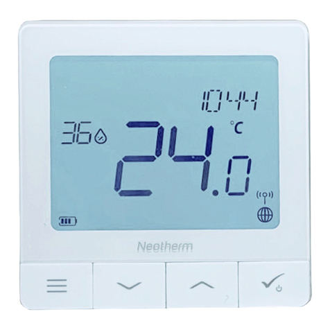
Nexans N-COMFORT TD+ User manual

THERMOSTAT
N-COMFORT TD+
USER MANUAL

2
EN OLED THERMOSTAT ................................................7
FI OLED-TERMOSTAATTI...............................................17
NO OLED-TERMOSTAT.................................................27
SE OLED-TERMOSTAT ..................................................38

3
1 / 8
The Bluetooth® trademark and logos are property of
BluetoothSIG,Inc.,andtheirusageislicensendforTaelek
Oy. Other brands and trade names are property of the
respectiveowners.
Apple, the Apple logo, iPhone, iPad, and iPod touch are
trademarksofAppleInc.,registeredin the U.S. and other
countries.AppStoreisaservicemarkofAppleInc.
Google Play and the Google Play logo are trademarks of
GoogleInc.
TSENSE OLED THERMOSTAT USER MANUAL
USER INTERFACE
WIRING
END USER
FUNCTIONS
REMOVAL OF
VISUAL PARTS
EN OLED THERMOSTAT ................................................7
FI OLED-TERMOSTAATTI...............................................17
NO OLED-TERMOSTAT.................................................27
SE OLED-TERMOSTAT ..................................................38
USER INTERFACE

4
1 / 8
The Bluetooth® trademark and logos are property of
BluetoothSIG,Inc.,andtheirusageislicensendforTaelek
Oy. Other brands and trade names are property of the
respectiveowners.
Apple, the Apple logo, iPhone, iPad, and iPod touch are
trademarksofAppleInc., registeredintheU.S.andother
countries.AppStoreisaservicemarkofAppleInc.
Google Play and the Google Play logo are trademarks of
GoogleInc.
TSENSE OLED THERMOSTAT USER MANUAL
USER INTERFACE
WIRING
END USER
FUNCTIONS
REMOVAL OF
VISUAL PARTS
WIRING
1 / 8
The Bluetooth® trademark and logos are property of
BluetoothSIG,Inc.,andtheirusageislicensendforTaelek
Oy. Other brands and trade names are property of the
respectiveowners.
Apple, the Apple logo, iPhone, iPad, and iPod touch are
trademarksof AppleInc.,registeredinthe U.S.and other
countries.AppStoreisaservicemarkofAppleInc.
Google Play and the Google Play logo are trademarks of
GoogleInc.
TSENSE OLED THERMOSTAT USER MANUAL
USER INTERFACE
WIRING
END USER
FUNCTIONS
REMOVAL OF
VISUAL PARTS

5
1 / 8
The Bluetooth® trademark and logos are property of
BluetoothSIG,Inc.,andtheirusageislicensendforTaelek
Oy. Other brands and trade names are property of the
respectiveowners.
Apple, the Apple logo, iPhone, iPad, and iPod touch are
trademarksof AppleInc.,registeredinthe U.S.and other
countries.AppStoreisaservicemarkofAppleInc.
Google Play and the Google Play logo are trademarks of
GoogleInc.
TSENSE OLED THERMOSTAT USER MANUAL
USER INTERFACE
WIRING
END USER
FUNCTIONS
REMOVAL OF
VISUAL PARTS
REMOVAL OF
VISUAL PARTS

6
1 / 8
The Bluetooth® trademark and logos are property of
BluetoothSIG,Inc.,andtheirusageislicensendforTaelek
Oy. Other brands and trade names are property of the
respectiveowners.
Apple, the Apple logo, iPhone, iPad, and iPod touch are
trademarksofAppleInc., registered intheU.S.and other
countries.AppStoreisaservicemarkofAppleInc.
Google Play and the Google Play logo are trademarks of
GoogleInc.
TSENSE OLED THERMOSTAT USER MANUAL
USER INTERFACE
WIRING
END USER
FUNCTIONS
REMOVAL OF
VISUAL PARTS
END USER FUNCTIONS

7
EN
Installation and operating instructions
N-COMFORT TD+ Thermostat – SETUP
TECHNICAL SPECIFICATIONS
Bluetooth: Bluetooth: Version 4.2
Power supply: 230V - 50Hz
Maximum load: 16A (resistive)
Temperature range: +5°C/+35°C
External Temperature setback: 230V - 50Hz
IP class: IP21
Standard Color: White
Sensors: Built-in room sensor and external oor sensor NTC or wireless
BLE sensor
INSTALLATION
Installation must be done by a qualied electrician in accordance with
wiring and building regulations. Before installation, disconnect any power
to the thermostat’s mains.

8
In a factory new thermostat the front cover (A) and frame (B) are loose and
you can just pull them out. If the visual parts are xed then push the rotary
dial (C°) hard downwards and while holding it down turn anti-clockwise.
The front cover and the frame can now be pulled away easily.
Connect the wires to the thermostat’s terminal: SETBACK: External Setback
Wire (if applicable), HEATING (N): Heating Cable N connection, N: Power
N connection, FLOOR SENSOR: Floor temp sensor NTC, HEATING (L): Hea-
ting Cable L connection, L: Power L connection.
Next, position the thermostat and fasten it into the wall mounting box using
2-4 screws. Assemble the frame. Check that xing nails are in ’LOCK’
position. If not use screwdriver to push them to correct position. Push the
front cover until it snaps in place. The front cover should now be rmly xed
on all sides.
STARTUP
After connecting the power to the thermostat for the rst time thermostat
recognizes if oor sensor is connected or not and makes initialization
accordingly (selects between oor mode and air mode). The following
settings are initialized accordingly (oor/air).
Name of thermostat: RANDOM number
Mode: Floor / Air
Floor temperature min: 5°C / NaN

9
Floor temperature max: 27°C / NaN
Floor temperature offset (calibration): -3°C
Air temperature min: 5°C
Air temperature max: 28°C
Air temperature offset (calibration): 0°C
PWM min: 0%
PWM max: 100%
Snow melting ON temperature min: 0°C
Snow melting ON temperature max: 10°C
Snow melting OFF temperature: -25°C
Snow melting air humidity min: 30%
User program activated eco temp: 19°C
Externally activated eco temp: 19°C
Valve protection: OFF
Sensor type: 10k ohm
Display brightness in standby: 70%
Weekly program: OFF
Use N-Comfort app to check and modify settings.
N-COMFORT TD+ THERMOSTAT – USER MANUAL
BASIC USE
The thermostat is controlled by rotary dial (C°) and a touch button (SET).

10
The basic use of thermostat is described in picture END USER FUNCTIONS:
1. Normal mode with dim screen saver display. Use rotary dial to step into
active mode (2).
2. Active mode. Rotating the dial takes you to modify the set temperature
of a current operating state (3).Touching the set button enters the menu (4).
3. Adjust the temperature set value of the current state (comfort, eco or ex-
ternally activated setback eco). Return to the start by touching the set button
or automatically after a timeout period.
Notice that in set value page current operating state is shown under the set
temperature digits. A ash symbol is indicating the relay activity.
4. In menu you can step from function to function with the rotary dial and
then enter the function by touching the set button:
• Touch the set button to select comfort state and adjust the
temperature set value with rotary dial. Return back to start by
touching the set button.
• Select eco mode by touching the set button and adjust with
rotary dial the set point of user program eco temperature or the
setback eco temperature (if setback input active). Return to the
start by touching the set button.
• Display the current heating mode

11
• Switch off the power by touching the set button. Power is
switched on by rotating the dial.
• Display the link to user manuals (QR-code link)
• From EXIT you return to the start by touching the set button.
ADVANCED USE
User may use a mobile device with N-Comfort App (Android / iOS) to read
log temperatures, to make settings and to dene a weekly user program.
App can also generate email reports. Follow the guides in N-Comfort app.
A Thermostat indicates the mobile device connection with Bluetooth symbol
on display.
1 Settings
Thermostat has several settings which can easily be adjusted by N-Comfort
app.
Name of thermostat
Name shown in N-Comfort app
Heating mode
Thermostat can measure and adjust oor temperature, air temperature, air
temperature with oor limits (dual), heating ratio (PWM control) or it can
melt snow and ice from stairs and driveways in snow melting mode.

12
Floor temperature min and max
This setting has two main purposes. In oor mode min and max values
specify active range of dial. In dual mode this setting does not effect the dial
but thermostat keeps oor temperature between limits. Feature can be used
to protect wooden oors (max limit) or to guarantee warm oor in room
with replace, e.g. Note: N/A in PWM and in air mode.
Floor temperature offset (calibration)
If user’s temperature measurement has offset to dial setpoint this setting
is used to calibrate. Note, oor sensor inside oor construction is much
warmer than real temperatures measured in room. Thus default is -3C to
have rotary dial adjustment range in realistic area of 18C...24C.
Air temperature min and max
This setting has two main purposes. In air and dual mode it species ac-
tive dial range. In all other modes it can be used as air over temperature
protection.
Air temperature offset (calibration)
If user’s temperature measurement has offset to dial setpoint this setting is
used to calibrate.
PWM min and max
This setting has two main purposes. In PWM mode min and max values
specify active dial range. In all other modes it guarantees maximum pulse

13
ratio. Note: Setting can be used, e.g., to limit maximum heating power
to comply with installation standard EN50599. Cycle time of PWM is 10
minutes.
Snow melting ON temperature min and max
Min and max setting specify the active knob range. When outdoor tempe-
rature is below this setting point the snow melting operation is active.
Snow melting OFF temperature
When it is colder than this temperature the snow melting is switched OFF.
Snow melting air humidity min
When wireless outdoor temperature sensor is used the thermostat also
receives air humidity level. Snow melting function will not be activated if the
air humidity is below this limit.
User program activated eco temp
During all green hours in user program the temperature is adjusted to this
value. This set value is also used when eco state is seleced from the menu.
Externally activated eco temp
When 230VAC (pilot signal) is connected to the setback input terminal the
temperature set value is dened by this parameter.

14
Valve protection
Valve protection turns heating ON once per week for 5 minutes even at sum-
mer time. This setting is typically used with water carrier oor heating valves.
Feature prevents the valve from getting stuck during summer.
Sensor type
Floor sensors from different manufacturers can be used. Supported types
are 2k, 10k, 12.5k, 15k, 33k NTCs.
Display brightness in standby
Brightness of the OLED display when it is dimmed in standby mode. Notice
that standby brightness affects the lifetime of OLED display.
User program mode
AUTO enables the user program, OFF disables it.
Wireless temperature sensor
Adding a wireless BLE temperature sensor allows the best location for tem-
perature measurement. It is very accurate and also measures the air humi-
dity. To add a wireless sensor you have to select it in the N-Comfort app
and write the sensor address in Network key elds.
Receive wireless eco controls
A thermostat with an external setback switch can control several other ther-
mostats to go in setback mode. This feature will save the user from hard

15
wiring the Home/Away switch to many thermostats. To form a group of
thermostats you need to enable the Receive wireless eco controls and write
a freely selectable group name in Network key elds.
Network key and Conrm Network key
Network key is used to identify the wireless temperature sensor or the group
of thermostats to receive the wireless eco controls. Both elds need to have
exactly the same text string and you have to save the settings. For the wire-
less sensor you can use the QR code printed on the back side of the device.
Just use the app camera function (bottom of the screen) to read the code,
then accept and save it.
2 Week schedule
User can create 7d/24h week schedule in N-Comfort app. With week
schedule the user programs thermostat to decrease temperature during
time slots when room is not used. Comfort/eco state is indicated on the
set value page.
Week schedule execution needs correct real time in thermostat. In case of
invalid real time the week program is deactivated and user is warned by
the error message on screen. Real time is updated from N-Comfort app
every time the thermostat is connected to a mobile phone. Real time has
backup to power shortages of up to 2 hours.

16
3 Error modes
Thermostat indicates an erratic state by displaying the text ERROR and the
error code. The most typical case is that real time is corrupted during too
long power break. This is automatically solved by taking connection with
N-Comfort app. Possible error codes are
1Floor sensor fault
2Over heat
3Internal fault
10 Calendar time is not valid
In errors 1, 2, 3 heating is permanently off. In error 10 user program is
deactivated.
You may try to reset the fault by switching off the power, to soft reset or by
using N-Comfort app to generate a hard reset.

17
FI
Asennus- ja käyttöohje
N-COMFORT TD+ termostaatin ASENTAMINEN
TEKNISET TIEDOT
Bluetooth: Versio 4.2
Käyttöjännite: 230V - 50Hz
Maksimikuorma: 16A (resistiivinen)
Käyttölämpätila: +5°C/+35°C
Ulkoinen ohjaus: 230V - 50Hz
IP-luokka: IP21
Väri: Valkoinen
Anturit: Sisäinen huoneanturi, ulkoinen lattia-anturi NTC. Mahdolllisuus
kytkeä ulkoinen langaton anturi (Bluetooth).
ASENNUS
Tuotteen saa asentaa vain valtuutettu ja pätevä asentaja paikallisten
määräysten mukaisesti. Varmista sähkönsyötön jännitteettömyys ennen
asennusta.

18
Uudessa laitteessa keskiölevy (A) ja kehys (B) ovat irti ja voit vetää ne ulos.
Jos muoviosat on painettu paikalleen niin vapauta keskiölevy painamalla
nuppia (C°) voimakkaasti alaspäin ja kääntämällä samalla vastapäivään.
Kehys ja keskiölevy voidaan nyt vetää ulos.
Kytke johdot termostaatin liittimeen: TIPUTUS: Ulkoinen ohjaus (jos käytös-
sä), KUORMA (N): Kuorman nollajohdin, N: Syötön nollajohdin, FLOOR
SENSOR: Lattia-anturi NTC, KUORMA (L): kuorman vaihejohdin, L: Syötön
vaihejohdin.
Seuraavaksi kiinnitä termostaatti asennusrasiaan 2-4 ruuvilla. Kierrä kiin-
nityskynnet ruuvimeisselin avulla ’LOCK”-asentoon. Laita kehys paikalleen
ja paina keskiölevy haluttuun syvyyteen siten, että se on suorassa ja kehys
tiukasti paikallaan.
KÄYNNISTYS
Ensimmäiselllä käynnistyskerralla termostaatti tunnistaa onko lattia-anturi
kytketty ja laite alustuu joko lattia- tai huonesäädölle. Asetusten oletusarvot:
Termostaatin nimi: satunnaisluku
Toimintatila: Lattia / Huone
Lattialämpötila min: 5°C / ei käytössä
Lattialämpötila max: 27°C / ei käytössä
Lattia-anturin kalibrointi: -3°C

19
Huonelämpötilan min: 5°C
Huonelämpötilan max: 28°C
Huoneanturin kalibrointi: 0°C
PWM min: 0%
PWM max: 100%
Sulanapito päälle min: -5°C
Sulanapito päälle max: 15°C
Sulanapito pois: -25°C
Sulanapito ilmankosteus min: 30%
Viikko-ohjelman käyttämä eco-lämpötila: 19°C
Ulkoisesti aktivoitava eco-lämpötila: 19°C
Toimilaitteen juuttumissuoja: OFF
Lattia-anturi: 10kOhm
Näytön kirkkaus lepotilassa: 70%
Viikko-ohjelma: OFF
N-Comfort App:n avulla voit tarkistaa ja muuttaa asetuksia.
BLUETOOTH-TERMOSTAATIN KÄYTTÖOHJEET
PERUSKÄYTTÖ
Termostaattia ohjataan kierrettävällä nupilla (C°) ja kosketuspainikkeella
(SET). Peruskäyttö on kuvattu ensimmäisellä sivulla, ks kuva END USER
FUNCTIONS:

20
1. Normaali toiminta, lepotila ja näyttö himmeänä. Kierrä nuppia siirtyäk-
sesi aktiiviseen tilaan (2).
2. Aktiivinen tila. Kiertämällä nuppia pääset muuttamaan nykyisen toim-
intatilan lämpötilan asetusarvoa (3).Koskettamalla painiketta siirryt valik-
kosivulle (4).
3. Säädä nykyisen tilan (comfort, eco tai ulkoisen tiputuksen eco) asetus-
arvoa. Palaa alkuun koskettamalla valintapainiketta tai odottamalla hetken
aikaa.
Huomioi että asetusarvosivulla näytetään tilatietoja asetuslämpötilan ala-
puolella. Nykyinen toimintatila on alleviivattuna. Keskellä riviä näkyvä sa-
lama-symboli kertoo että lähtö on aktiivinen (lämmitin päällä).
4. Valikossa siirryt toimintorivistä toiseen kiertämällä nuppia ja toimintoon
siirryt kosketuspainikkeen avulla:
• Valitse painikkeella comfort-tila ja säädä asetusarvo halutuksi
nuppia kiertämällä. Palaa alkuun kosketuspainikkeella.
• Valitse painikkeella eco-tila ja säädä asetusarvo halutuksi
nuppia kiertämällä. Palaa alkuun kosketuspainikkeella. Jos
tiputustulo on aktiivinen, muutat sen asetusarvoa, muuten
viikko-ohjelman eco-tilan asetusarvoa. Palaa alkuun kosketta-
malla valintapainiketta.
• Näytä nykyinen toimintatila
This manual suits for next models
1
Table of contents
Languages:
Other Nexans Thermostat manuals

