Distek Premiere 5100 User manual
Operation
Manual
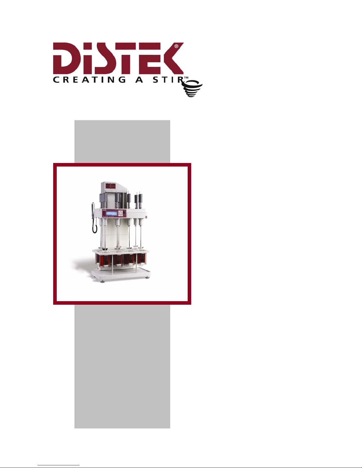
Premiere 5100
Dissolution Test System

About This Manual
Operation Manual: Model 5100 i
Distek Premiere 5100 Dissolution Test System
Operation Manual
Document # 3851-0020
Distek, Inc.
121 North Center Dr. • North Brunswick, NJ 08902
Phone 732.422.7585 • Fax 732.422.7310
http://www.distekinc.com

About This Manual
Operation Manual: Model 5100 ii
Notice
This document contains proprietary information. All rights are
reserved. No part of this document may be photocopied,
reproduced or translated without the prior written consent of
DISTEK Incorporated.
DISTEK, INC.
121 North Center Drive
North Brunswick, NJ 08902-4905
Tel. (732) 422-7585
Fax. (732) 422-7310
Website: http://www.distekinc.com
“Dow Corning” is a registered trademark of Dow Corning Corporation, USA.
IBM and IBM PC are registered trademarks of IBM Corp.
CenterChek, HeightChek, RPMChek, ShaftChek, and TempChek are trademarks
of DISTEK, Inc.
The DISTEK logo is a registered trademark of DISTEK, Inc.
All other company and product names are trademarks or registered trademarks
of their respective holders.
Document Revision History
Rev Date Document Notes
A September 1996 3851-0020
B March 1997 3851-0020
C December 1997 3851-0020
D June 2002 3851-0020
E August 2003 3851-0020 See Distek Change Notice 0381

About This Manual
Operation Manual: Model 5100 iii
Contents
About this Manual .............................................................................vi
Purpose ......................................................................................... vii
Audience........................................................................................ vii
Contents ........................................................................................ vii
Prerequisites .................................................................................. viii
Documentation ............................................................................... viii
Conventions ................................................................................... viii
1Introduction...........................................................................1-1
Specification .................................................................................. 1-2
Overview....................................................................................... 1-3
2Installation ............................................................................2-1
Unpacking ..................................................................................... 2-2
To remove packing....................................................................... 2-2
Leveling: Model 5100 ........................................................................ 2-3
To level unit on bench .................................................................. 2-3
Positioning the Vessels ...................................................................... 2-6
To install vessels in vessel plate....................................................... 2-6
Paddles and Baskets ......................................................................... 2-6
To install paddle blades................................................................. 2-6
To install baskets ........................................................................ 2-6
Checking paddles, baskets and shafts for straightness ............................ 2-8
Checking shaft centering ............................................................... 2-8
Installing the Calibration Probe............................................................ 2-8
To install calibration probe ............................................................ 2-8

About This Manual
Operation Manual: Model 5100 iv
Adjusting the Paddle (or Basket) Height ................................................. 2-9
To set height of paddle or basket ................................................... 2-11
Installation Checkout ...................................................................... 2-12
RPM Control ............................................................................. 2-12
Test Duration ........................................................................... 2-12
Temperature Control .................................................................. 2-12
Time and Date .......................................................................... 2-13
3Operation.............................................................................. 3-1
To Run a Pre-programmed Automatic Test .......................................... 3-5
Control Keypad ............................................................................... 3-7
Stir Key .................................................................................... 3-7
Arrow Keys ................................................................................ 3-7
Enter Keys ................................................................................. 3-7
Clear Key .................................................................................. 3-7
START Key ................................................................................. 3-7
Sleep Key (System Standby) ............................................................ 3-8
Display and Control Screens ................................................................ 3-8
Display Screens ........................................................................... 3-9
For Method History Information ..................................................... 3-12
Automatic Testing Methods............................................................... 3-13
Select Method .......................................................................... 3-13
Edit Test Method ....................................................................... 3-14
Pre-Test Initialization ................................................................. 3-18
START Test Using Paddles ............................................................ 3-19
Program New Auto Test ............................................................... 3-23
Delete Test Method .................................................................... 3-24
Basket Testing .......................................................................... 3-24
Manual Operation .......................................................................... 3-25
Set RPM .................................................................................. 3-26
Controlling Vessel Individually ....................................................... 3-26
Controlling All Vessels Together ..................................................... 3-27
System Setup and Calibration ............................................................ 3-29
Introduction............................................................................. 3-29
Calibrate Using 5100 Calibration Probe ............................................ 3-30
Calibrating Using TempChek Digital Thermometer ............................... 3-36
Calibrating Using NIST Traceable Reference Thermometer..................... 3-44
Advanced Setup Options .............................................................. 3-53
Printouts ..................................................................................... 3-54
Serial Port Control of 5100 ............................................................... 3-57
RS-232 Port.............................................................................. 3-57
Serial RS-485 Address and Beep Mode .................................................. 3-61
4Maintenance ..........................................................................4-1
General Care and Maintenance of Model 5100 .......................................... 4-2

About This Manual
Operation Manual: Model 5100 v
5Troubleshooting & Service.......................................................... 5-1
Troubleshooting Chart....................................................................... 5-3
Model 5100 System Initialize Procedure ................................................ 5-19
Clearing the Dallas Chip................................................................... 5-21
Replacing Chip Number U13 .............................................................. 5-21
Function Check and Initialize Instrument .............................................. 5-22
Initialize Unit ............................................................................... 5-22
Service ....................................................................................... 5-24
Appendix A: Spare Parts and Accessories ................................................A-1
Appendix B: Preventive Maintenance Checklist .........................................B-1
Appendix C: Pre-Installation Considerations: Electrical Power Supply ..............C-1
Appendix D: CE Declaration of Conformity ..............................................D-1
Appendix E: Certificate of Compliance ................................................... E-1
Appendix F: Sample Printouts from Parallel Printer.................................... F-1

About This Manual
Operation Manual: Model 5100 vi
About this Manual
About This Manual includes information about what is contained in this manual
and the conventions used.
Purpose ......................................................................................... vii
Audience........................................................................................ vii
Contents ........................................................................................ vii
Prerequisites .................................................................................. viii
Documentation ............................................................................... viii
Conventions ................................................................................... viii

About This Manual
Operation Manual: Model 5100 vii
Purpose
This manual covers the installation, routine operation, maintenance and repair
of your Model 5100 Dissolution Test System. It contains information regarding
the commands, menus, indicators and controls. Chapter 1 provides an overview
of the 5100. Chapter 2 covers unpacking, installation, and qualification of the
system. Chapter 3 contains operation and programming information. Chapters
4 and 5 cover maintenance and troubleshooting. Please read Chapters 1, 2
and 3 before proceeding.
Audience
This manual is written for any person responsible for maintaining, operating or
troubleshooting the Distek Premiere 5100 Dissolution Test System.
Contents
This manual is divided into chapters. The pages of the manual are numbered
providing easy navigation to assist in finding information quickly.
The following list describes the material covered in each chapter:
Table 1: Chapter Descriptions
Chapter 1 - Introduction Provided a general overview and
warnings about the instrument.
Chapter 2 - Installation Describes how to unpack and properly
install the unit.
Chapter 3 - Operation Describes how the functionalities of
the system and how to run the unit.
Chapter 4 - Maintenance Explains the steps necessary to
maintain the unit.
Chapter 5 – Troubleshooting & Service Provides and troubleshooting chart
and description of error messages to
assist the user is a problem should
arise.
Appendix A – Spare Parts and
Accessories
Provides a table of recommended and
optional spare parts.
Appendix B - Preventive Maintenance
Checklist
Provides a checklist of preventive
maintenance actions.
Appendix C - Pre-Installation Recommendation information
About This Manual
Operation Manual: Model 5100 viii
Considerations: Electrical Power
Supply
pertaining to electrical power supply.
Appendix D - CE Declaration of
Conformity
CE Declaration of Conformity
certificate.
Appendix E - Certificate of Compliance Certificate of Compliance
Appendix F - Sample Printouts from
Parallel Printer
Sample printouts for a parallel printer.
Prerequisites
This manual assumes that you understand the principles of dissolution testing.
Documentation
This manual contains important information regarding the safe operation,
maintenance and repair of your Distek Premiere 5100 Dissolution Test System.
We urge you to read Sections 1, 2, and 3 before proceeding.
Conventions
The following table lists conventions and terms used throughout this manual:
Table 2: Conventions
“WARNING” statements are used in this manual to prevent
injury to personnel.
\“CAUTION” statements are used to prevent damage to
equipment.
“NOTES” contain helpful information.
REQUIRED
ACTION
Used where necessary to distinguish the action needed from
the Warnings, Cautions and Notes.

Chapter 1: Introduction
Operation Manual: Model 5100 1-1
1Introduction
The Distek Premiere 5100 Dissolution Test System is a state of the art instrument.
This chapter will introduce the user to the unit.
Specification .................................................................................. 1-2
Warnings and Notes .......................................................................... 1-3

Chapter 1: Introduction
Operation Manual: Model 5100 1-2
Specification
The Distek Premiere 5100 dissolution system utilizes state of the art electronics, solid
state components, and advanced materials to provide the fastest, cleanest, and most
cost effective dissolution testing solution available today. The 5100 has intelligent
programming features that allow individual vessel control of heating profile, remote
programming and control, and comprehensive method reporting, documentation, and
validation.
Table 3: System Specifications
Dissolution Vessels: 7 built-in vessel positions
Volume: 500mL to 1000mL, programmable
Heating Time (20-37ºC) Approximately 15-20 minutes, 0.3º C
maximum overshoot
RPM Control Range: 25-300 RPM, digitally controlled, closed loop
Resolution: 0.1 RPM
Accuracy: +/- 0.2 RPM from 50-150 RPM
Display: 0.75” (19mm) high output four-digit LED
Motor: High Torque, Permanent Magnet
Vessel Temperature
Control:
Each individual vessel is continuously
monitored and controlled.
Display Resolution: 0.01º C
Accuracy: +/- 0.25º C
Calibration: Built-in Calibration Probe
Shaft Wobble: Less than 0.010” (0.254mm) TIR
Program Modes: Manual (individual vessel control)
Automatic (30 pre-programmed methods)
External (ProduKey memory device)
Interface Ports: RS-232 (1), RS-485 (2), Parallel Printer
Construction Materials: Cast Aluminum, Stainless Steel, Acid
resistant solid state heating elements,
Engineered Plastics
Dimensions: 27”(W) x 37”(H) x 19”(D) (68.6 x 94.0 x
48.3cm Deep)
Weight: 150 lb. (68kg)
Electrical Power: 115V 50/60Hz 15A or 220V 50/60Hz 8A
(Operating voltage pre-set at factory)
Chapter 1: Introduction
Operation Manual: Model 5100 1-3
Warnings and Notes
Improper servicing or adjustment practice can cause
equipment failure or serious physical injury. This
equipment must be adjusted and serviced by qualified
electrical maintenance personnel who are familiar with
the construction and operation of the equipment and
the hazards involved. Take diligent care during
adjustment. All exposed points on the control circuit
boards are electrically hot with respect to earth ground.
HIGH VOLTAGE IS EXPOSED WHEN THE LOWER REAR
PANEL IS OPENED ON THE 5100. Dangerous voltages
exist on the circuit boards when powered.
Disconnect AC power from the 5100 while
troubleshooting. Be alert. High voltage can cause
serious or fatal injury.
The Model 5100 is supplied with proper heaters and
settings for the specified operating voltage (see label
for information). Do not attempt to convert unit to
another power supply without contacting the factory
first!
Take care when removing or replacing vessel
heaters. Turn off unit and disconnect power from
5100. Do not use metal tools or sharp objects to
mount heater. Heater failure and/or injury could
result.
Heater surfaces may be HOT. Do not touch vessel
heater assemblies, when 5100 is in operation. Injury
may result.
Take proper precautions when handling dissolution
media. Liquid in vessel may be HOT. Wear
protection from splash to avoid exposure to
scalding, acidic, caustic, or pharmaceutical hazards.
Bacteria have been shown to thrive in certain
media, especially at test temperatures.
Improper remote PC control of 5100 may lead to
unexpected motor and/or heater operation. Make
sure personnel are clear before issuing PC
commands.
Chapter 1: Introduction
Operation Manual: Model 5100 1-4
\
To avoid damaging the instrument:
•Do not operate heaters with less than 500ml liquid
in each vessel.
•The stirring element (paddle or basket) must be
immersed into the liquid and rotating when heaters
are operating.
•Use only glass vessels supplied for the model 5100
by Distek.
•Connect this unit to the specified AC supply.
Observe proper grounding.
•Failure to observe these precautions may
damage the heater assemblies and/or vessels.
\
To avoid glass breakage and injury:
♦Do not heat vessels empty.
♦Do not clean with materials that scratch.
♦Do not bump.
♦Discard vessels if cracked, scratched, or heated
empty.
All Distek 5100 heaters have thermostatic protection.
In the event of a malfunction (or if no liquid in vessel),
the heater will cut off at approximately 150ºC.
Thermostat automatically resets after cooling down.
The 5100 incorporates a height sensor to stop rotation
and heating whenever the drive unit is raised well
above operating position. This feature helps to
prevent overheating and addresses safety issues. To
resume rotation and heating, return drive unit to
operating position and press START key.
External cables (excluding power cable) are limited to less
than 3 meters length in order to maintain electromagnetic
compliance.
Some forms of electromagnetic interference may cause
unexpected operation. If this occurs, the unit will return
to normal operation once the interference is removed.

Chapter 2: Installation
Operation Manual: Model 5100 2-1
2Installation
This chapter describes the steps necessary to properly unpack and install the
instrument.
Unpacking ..................................................................................... 2-2
To remove packing....................................................................... 2-2
Leveling: Model 5100 ........................................................................ 2-3
To level unit on bench .................................................................. 2-3
Positioning the Vessels ...................................................................... 2-6
To install vessels in vessel plate....................................................... 2-6
Paddles and Baskets ......................................................................... 2-6
To install paddle blades................................................................. 2-6
To install baskets ........................................................................ 2-6
Checking paddles, baskets and shafts for straightness ............................ 2-8
Checking shaft centering ............................................................... 2-8
Installing the Calibration Probe............................................................ 2-8
To install calibration probe ............................................................ 2-8
Quick Change Height Adjustment Knob................................................... 2-9
To set height of paddle or basket ..................................................... 2-9
Adjusting the Paddle (or Basket) Height ............................................... 2-11
To set height of paddle or basket ................................................... 2-11
Installation Checkout ...................................................................... 2-12
RPM Control ............................................................................. 2-12
Test Duration ........................................................................... 2-12
Temperature Control .................................................................. 2-12
Time and Date .......................................................................... 2-13

Chapter 2: Installation
Operation Manual: Model 5100 2-2
Unpacking
To avoid injury, two people should remove 5100 from carton.
\Do not bump or disturb built-in paddle shafts as this may affect shaft
runout.
\The drive unit is locked in place during shipping.
Please take a few moments when unpacking unit to check for all
items indicated on packing list. Notify DISTEK or your shipper
immediately of any discrepancies or damage to cartons or contents in
transit.
Packing must be removed before operating this instrument.
To remove packing
1. Cut through tape at top of carton. Open four top flaps.
2. Carefully remove packing inserts and lift instrument from shipping carton.
See warning and cautions above.
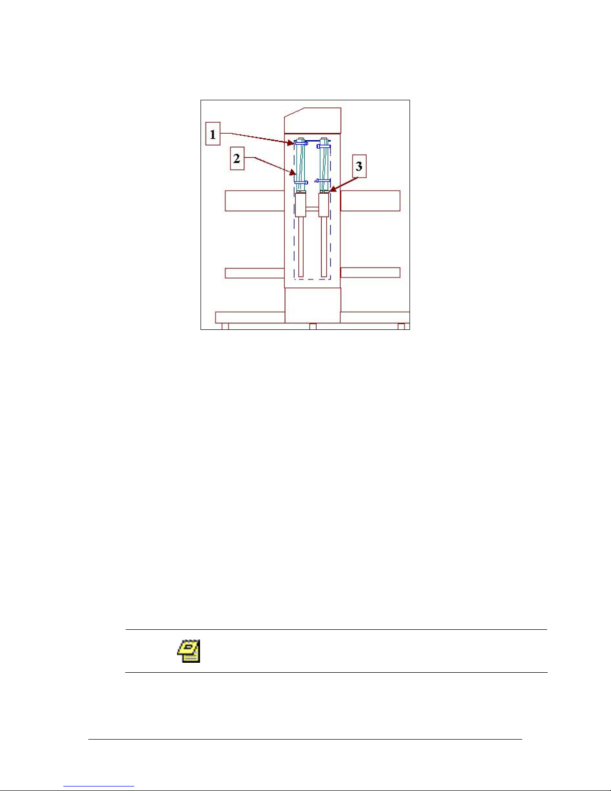
3. If drive unit is locked in place, tie-wraps are visible from the front of the
unit, above the bearings (see item 1 below).
4. Identify & cut the tie-wraps on the guide rods above the bearings and
remove split tubing (see item 2 below).
5. Remove split washer (item 3) from top of each bearing.
6. Press brake release key (see Figure 2-3) and gently raise or lower drive unit.
7. Let go of brake release key to set drive unit at desired height.
Chapter 2: Installation
Operation Manual: Model 5100 2-3
Figure 2-1: Rear View – Inside
The power cord is shipped in a separate carton from the main unit. Connect
power cord supplied to 5100 below power switch (see Figure 2-3). Locate
proper outlet for 5100. See Appendix C for electrical power requirements.
Leveling: Model 5100
To level unit on bench
1. Trained personnel should lift unit onto bench and slide it into position.
2. Make certain the two stabilizers under rear of base are not touching bench.
3. Loosen locking nuts on front leveling feet, using the appropriate (1/2”)
wrench.
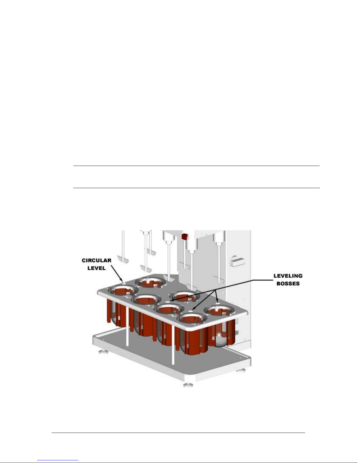
4. Observe permanently mounted circular level on vessel support plate.
5. Level unit from front to back and side to side by adjusting front two leveling
feet under instrument base (see Figure 2-3).
Do not loosen rear leveling foot. Level unit by adjusting front
leveling feet.
Chapter 2: Installation
Operation Manual: Model 5100 2-4
6. Required Action: Tighten locking nut on each foot at this time.
7. After leveling, adjust two stabilizers under rear of instrument base so that
they just touch bench.
8. Mark location of leveling feet on bench, to prevent changes in level due to
moving unit.
9. Check the level after completing installation, or after moving the Model
5100 to a new location. Verify accuracy of built-in circular level by placing
6-9” carpenter’s level on vessel plate leveling bosses (see Figure 2-2).
Check from front to back and side to side.
\
Connect this unit to the specified ac supply. Observe proper
grounding.
10.Plug Model 5100 into proper electrical outlet provided.
Figure 2-2: Leveling Model 5100
Chapter 2: Installation
Operation Manual: Model 5100 2-5
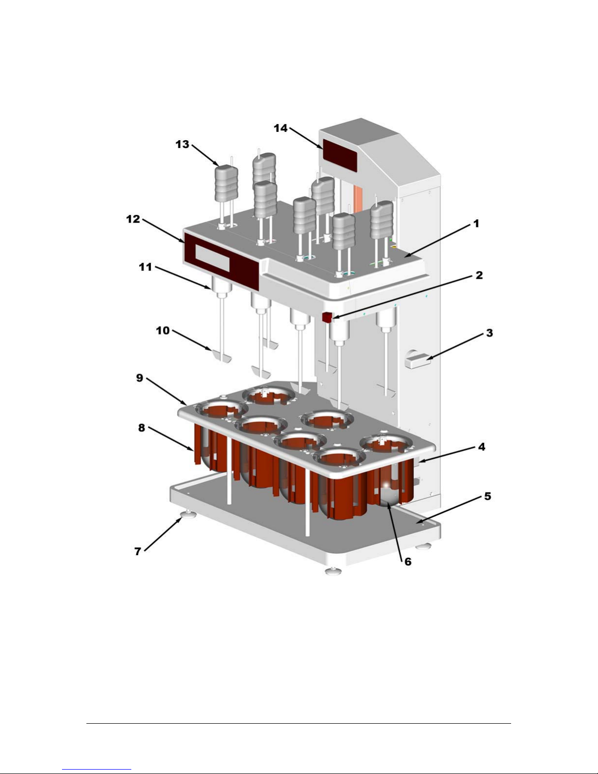
1. Drive Unit 6. Glass Vessel 11. Spindle Assembly
2. Brake Release 7. Leveling Feet 12. Front LCD Display
3. Height Adjustment Knob 8. Heater Assembly 13. Shaft Handle
4. Power Switch 9. Vessel Support Plate 14. Top LED Display
5. Base Plate 10. Paddle Blade
Figure 2-3: Model 5100 Installation

Chapter 2: Installation
Operation Manual: Model 5100 2-6
Positioning the Vessels
To install vessels in vessel plate
1. Raise drive unit.
2. Insert a vessel in each position on vessel plate.
3. Slide vessel through vessel clips until it can go no further.
Top of at least one vessel clip should contact bottom of vessel
flange.
\
DISTEK supplies highly uniform vessels that fit properly into
the 5100 heater assemblies. Use of vessels other than those
supplied by DISTEK for the 5100 may result in unsatisfactory
operation or heater damage and void the warranty.
Paddles and Baskets
To install paddle blades
Carefully screw a paddle blade onto bottom of each shaft. Assemble finger-
tight.
\
Do not grasp basket by mesh screen when installing or
removing. ALWAYS GRASP BASKETS BY KNURLED UPPER RIM.
Proper handling will prevent basket distortion and RESULTING
wobble.
To install baskets
1. Carefully screw a basket adapter onto bottom of each shaft. Assemble
finger-tight (see Figure 2-4).
2. Vessel pre-heat to be performed at 250 RPM with basket adapter only.
Baskets are not installed during pre-heat.

Chapter 2: Installation
Operation Manual: Model 5100 2-7
3. Always place tablet or capsule into a dry, empty basket before test.
4. When vessel stabilizes at test temperature, lift shaft out of vessel.
5. Place basket, open end up, in palm with thumb and fingers grasping knurled
grip (see Caution above.)
6. Raise basket until inside of knurled ring just contacts the O-ring shown in
Figure 2-4.
7. Twist and push basket onto adapter.
8. When removing basket, grasp only on the knurled grip. Pull down and twist.
Upon completion of each test, rinse baskets and shafts
thoroughly with distilled water. DO NOT ALLOW ACIDS
OR BUFFERS TO DRY ON THE METAL SURFACES.
Figure 2-4: Installing Basket on Shaft
\
Handle paddle blades and optional baskets carefully to avoid
bending or damage. Store carefully in original container to
prevent damage.
Table of contents
Other Distek Test Equipment manuals


