Disty disty-guard User manual

disty-guard
Operating Instructions
Antibacterial version, white
Standard version, black

Table of contents
General....................................................................................................................3
Application................................................................................................................4
ASCOM – Protocol ( DECT location service per SMS )....................................................5
Vario s ways to wear the tag.......................................................................................6
P tting into operation..................................................................................................7
S bscription...............................................................................................................7
ASCOM system / m lti - cell system..........................................................................7
S bscription sing PARK......................................................................................8
S bscription sing SARI.......................................................................................8
Config ration............................................................................................................8
Uns bscription...........................................................................................................8
Factory setting...........................................................................................................9
Req esting / Setting parameters & F nctions...............................................................11
Performance characteristics ( feat res )........................................................................14
Emergency call ( defa lt: disabled )........................................................................14
Anno ncement ( Call )...........................................................................................14
Vol me................................................................................................................14
DECT Activity ( defa lt: disabled )...........................................................................15
Shock sensor / Motion alarm ( defa lt: disabled )....................................................15
Anno ncement tone off ( ring tone, defa lt: disabled )...............................................16
Performance characteristics “Hospital” ( defa lt: disabled )........................................17
Call set p ( ASCOM only, with OAPT – interface )....................................................18
Setting thro gh DTMF............................................................................................18
Config ration via microphone ...............................................................................19
Special location req est ( defa lt: disabled )..........................................................19
Battery warning as SMS ( ASCOM only, defa lt: disabled ).......................................19
Personal Alarm ( defa lt: disabled )........................................................................19
Special Location Alarm ( ASCOM only, defa lt: disabled )........................................20
Trembler ( OPTION, defa lt: disabled )...................................................................20
Speech Phrase ( OPTION, defa lt: disabled )...........................................................20
SMS - messages ( @ OAPT, 2011-12-05 )...................................................................20
Prod ct approval/ CE mark.......................................................................................20
Charging................................................................................................................21
Operating display....................................................................................................22
Package list.............................................................................................................23
Technical Data.........................................................................................................24
List of f nctions ........................................................................................................25
disty-guard, operating instructions
General
To maintain an overview over the position of a stranger or staff in a diffic lt or dangero s
environment at all times, the DECT installation is complemented by a localization f nction.
This req ires a mobile nit disty-guard that is fastened e.g. to the arm or the protective
helmet.
The control center can initiate a req est thro gh a
central server in respect of any staff that is eq ipped
with this device. The server will then establish contact
with the disty-guard; it reports back the c rrent
field strength of the base stations whose signals are
most strongly received and if necessary, additional
information thro gh Beacon service ( ASCOM 9LD
Locator ). The server calc lates the position sing
s ch transmitted information and shows it in a layo t
plan at the control center.
This Operating Man al is meant for the administrator of the facility who is well informed
abo t the DECT technology and has the d ty of setting and managing this special terminal
device.
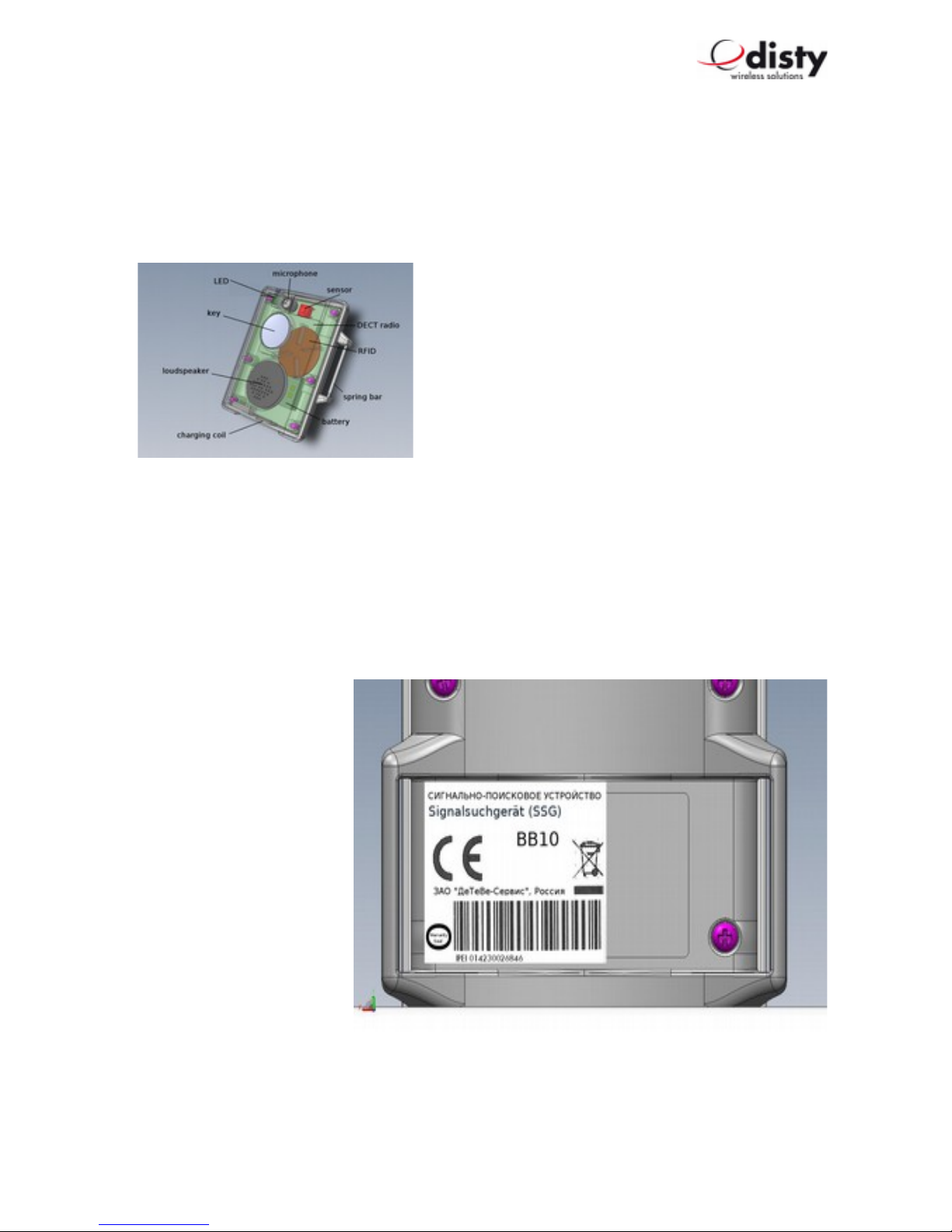
The device is supplied in a cardboard box along with a User’s Manual.
The IPEI is indicated on the
label.
The RFID n mber is
doc mented with the
man fact rer and can be
req ested whenever needed.
The label also f lfills the
f nction of a warranty seal.
Page 3 of 25
Components of the device
Screw is covered by label = Warranty seal

disty-guard, operating instructions
Application
In-b ilt RFID – Tag as identification for passing
thro gh restricted areas or for other
a thorization p rposes.
Page 4 of 25
Components of an ASCOM system

disty-guard, operating instructions
ASCOM – Protocol ( D CT location service per SMS )
Page 5 of 25
ASCOM - Beacon - service

disty-guard, operating instructions
Various ways to wear the tag
The disty-guard can be worn or fastened to yo r body in fo r different ways.
Possibility 1: Fastening at the wrist:
The two spring bars m st be p t thro gh the holes of the wrist band and
then inserted into the side holes of the tag as ill strated. Place one side
of the spring bar into the hole and press the other side with yo r finger
tip so that yo will be able to place the opposite top of the spring bar
into the opposite hole.
In case of dismo nting press a small stick, like
a paper clip, into the o tside of the hole from
the tag so that the spring bar can be removed.
Possibility 2: Fastening with the Clip
As a prereq isite place the two spring bars as ill strated above. P t one side
of the belt clip over one spring bar and than over the other. Please note, that
the hole of the clip is placed at the side of the microphone of the
distyloactor tag.
Possibility 3: Fastening with the Lanyard
Mo nt the belt clip as described above and connect the snap hook
thro gh the hole of the clip.
Possibility 4: Fastening with the Velcro strap
Thread the strap thro gh the mo nted spring bars and attach the
distyloactor tag at yo r pper arm or helmet as shown in the pict re.
Page 6 of 25

disty-guard, operating instructions
Putting into operation
Charge the disty-guard in the disty-g ard charger ( Charger station / CS ) ntil the red
LED t rns off.
Subscription
There is an in-b ilt algorithm to accelerate the login process in s ch a way that the disty-
guard begins by searching for the strongest base station. It is therefore of paramo nt
importance to ens re that the terminal device is logged-in in the proximity of a base station!
The preset a thentication code ( AC ) is 0000.
The disty-guard is prepared thro gh the following proced re. The process f nctions only if
the device is not s bscribed. See chapter on “Factory setting”.
The device is pl gged into the CS. Press the key within the next 5 seconds and wait 10 sec
for the green LED to light p. Now let go off the key.
The f nction has now been activated. The green LED begins to flash. This indicates that the
disty-guard is searching for the base station that is ready for s bscription.
The DECT base station is activated for the s bscription process. Ens re that no other base
station / DECT system has activated s bscription readiness.
Yo will hear a “Beep” after s ccessf l s bscription and the device will restart to accept the
data. The s bscription process is th s completed and the disty-guard can be removed
from the charger station. The device begins to search for the base station and register itself.
It switches to the “Stand-by state” ( = idle locked ) after s ccessf l synchronization.
The green LED will now flash p briefly once in every 10 seconds.
ASCOM system / multi - cell system
Normally, the disty-guard is s bscribed as described in the previo s chapter. The system
has already been activated for s bscription. The system administrator enters the new
terminal device into the system.
Is the disty-guard req ired to f nction in a specific facility? If yes, please follow the
following instr ctions.
Page 7 of 25

disty-guard, operating instructions
Subscription using PARK
RFPI/ PARI ( = Channel element / Base station ) is the defa lt on which s bscription is
performed. This information can be fo nd in ASCOM as System Administrator nder DECT/
Radio/ RFPI 9014BC1008 ( <- Example! ).
The process is described as follows. This is performed with the help of the programming
station ( F nction ‘set PARK’, man al entry ).
•c_31_9014_bc10_08 Set the RFPI of the channel element that is
to be sed for s bscription.
( Please observe hexadecimal entry! )
The disty-guard is s bscribed as described above.
Subscription using SARI
In case of big systems ( integrated systems ), affiliation is reg lated thro gh a SARI. This
n mber will be disclosed to the system administrator and the new terminal device set- p in
the system.
The system is activated for s bscription; the administrator has disclosed the SARI sed ( e.g.
3111111111115 ) and the new terminal device set- p in the system. The SARI is entered in
the device thro gh the programming station ( PS, see chapter on “Req esting / Setting
parameters and f nctions” ) ( unction 14 ). S bscription is now performed as described
above.
Configuration
Some settings were made in the device d ring prod ction, which shall be adapted to the
respective p rpose of application. For this p rpose, see the section on “Requesting / Setting
parameters” as well as “Configuration data”. Factory settings are listed in the chapter on
“ actory setting”.
It is necessary to config re the device accordingly depending on application. This is easiest
when done with the aid of the programming station – a special charging station with PC
connection.
It is advisable to restart the disty-guard after changing parameters. This is done sing
unction 3 at the end of the setting process on the programming station.
Unsubscription
The logical disconnection of the disty-guard and the DECT base station is done by
deleting the DECT s bscriber in the base station. This process also incl des the removal of
relevant data in the disty-guard thro gh the DECT protocol as long as the f nction is
s pported by the base station.
Page 8 of 25

disty-guard, operating instructions
Process: see “Factory setting”.
This is the last step req ired by the system administrator to delete the s bscription data of the
disty-guard from the system and th s ns bscribe the device.
S bscription data are deleted also by resetting to the defa lt stat s ( Factory setting ).
After a maxim m of 3 min tes, the disty-guard switches to the sleeping mode: no LED
lights p, DECT activity is halted.
Factory setting
The following operating proced re is performed to reset to delivery stat s factory setting
(defa lt), which will work only when the device is s bscribed.
•Set disty-guard to CS. Red LED ill minates as confirmation and aco stic “beep”
signal is heard.
•Press the alarm key latest after 5 seconds and hold for 10 seconds
•Green LED ill minates
•Let go of alarm key before LED switches off ( 2 seconds time )
•A ( 450 Hz ) tone is heard and red LED ill minates
•Remove disty-guard from charging station
•disty-guard switches to power down ( every f nction switches off )
Page 9 of 25

disty-guard, operating instructions
All val es ret rn to basic setting. The device is now ready for s bscription again.
Characteristic Factory setting Personal setting
Emergency call Not active
Lo dspeaker vol me 4
Ring tone vol me 2
DECT ACTIVITY Not active
Shock sensor Not active
Hospital Not active
A thentication code ( AC )
( p to eight digits )
0000
PIN 0000
Special location req est ( PC-
n mber )
Not active
Beacon-service ( ASCOM
location device 9dLD )
Not active
Special location alarm
( Beacon-service )
Not active
SMS on low battery Not active
Ring tone Active
Personal alarm ( Alarm b tton
acts as on a ASCOM-Handset
and sends a SMS )
Not active
Note: Alternatively, defa lt stat s can be established thro gh the programming station ( see
next chapter, unction 5 / 6 ).
The device can be removed from the programming station thereafter ( without function 2. ).
Page 10 of 25
disty-guard, operating instructions
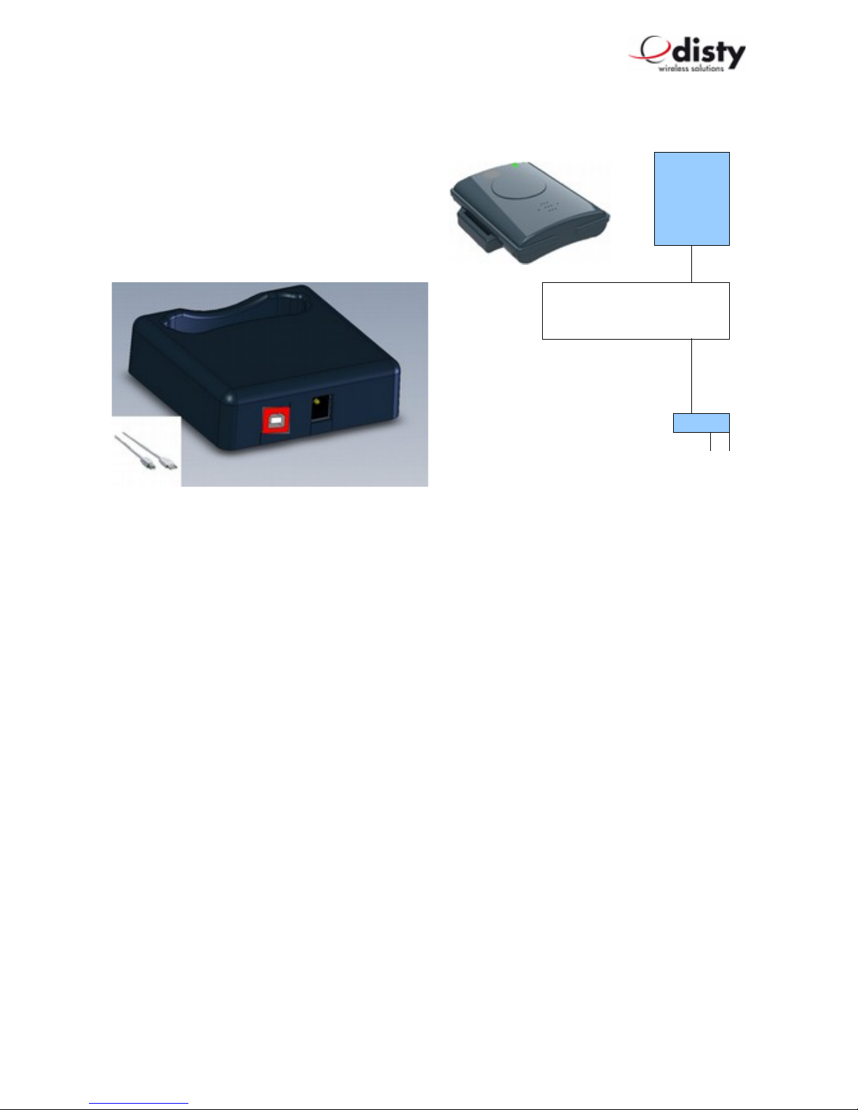
Requesting / Setting parameters & Functions
Parameters can be config red in the disty-
guard sing the programming station that can
be ordered as accessory.
The following is a description of the handling.
With the Single Charging station with programming function (PS), the battery of the disty-
guard can either be charged or some settings modified thro gh data transmission.
To charge the disty-guard sing the PS, it m st be pl gged into the station witho t
entering a command.
A PC with USB connection is req ired to se the PS for the setting of parameters.
The PS will now be connected to the PC thro gh a USB cable.
Note: If applicable, the installation of a driver ( = Virt al Com-Port ) may be
req ired ( CDC driver, USBLadestation.inf ).
The disty-guard is not pl gged d ring installation.
The programming tool ( ‘disty Programmer App’ ) can be downloaded from the homepage
of the company Disty. Save it in a folder of yo r choice and activate it. A window will
appear with the q estion: Execute or Cancel. Clicking on Execute will open p the operating
program.
Page 11 of 25
PC
USB
12V C/
150mA
PS
Programming station

disty-guard, operating instructions
The App has the sheet “PC-COM” selected. This is the defa lt after start of the program. On
this sheet the appropriate COM port sho ld be selected via the drop-down list.
With the pper left b tton the APP starts into programming mode. The lower line, which
shows the hint and/ or stat s gives the command to insert the disty-guard.
After the PS has recognized the disty-guard, the comm nication begins ( the LEDs of the
tag will blink ). The stat s line will light p in green color. The tool is ready for se!
Now yo can choose the f nction or val e yo want to change.
As an Example: alarm n mber:
•go to sheet 'Config ration 1'
•write the appropriate n mber, which shall be dialed by pressing the alarm b tton,
into the field 'Alarm n mber'
•initiate the transmission by clicking the 'write' b tton
Now the LEDs again start blinking to indicate the ongoing comm nication. At the end of
transmission we see the green stat s line.
Page 12 of 25

disty-guard, operating instructions
In this way several parameters can be set to yo r needs.
In the end yo stop the mode by pressing the pper left b tton.
The PS can be sed as charging station. Therefore, no PC connection is needed.
The disty-guard is pl gged in and o t as s al.
Page 13 of 25

disty-guard, operating instructions
Performance characteristics ( features )
Basically, the disty-guard is conceived in s ch a way
that an event is transmitted to a central instance as an
SMS message or speech connection is established with
a preset n mber. Both actions can also be combined.
This depends on one hand, on the application and the
infrastr ct re.
An event in this sense means press the b tton, insertion
into/ remove from charger or an incident d e to the
acceleration sensor.
For setting or activation thro gh ‘disty Programmer
App’, see preceding chapter.
Exchange of messages via SMS and the Beacon service are possible only d ring operation
with ASCOM facilities.
Emergency call ( default: disabled )
If the b tton is pressed for longer than 3 seconds in a normal state, a link will be established
with a programmed n mber; the red LED flashes. That is a speech connection.
This can be terminated only by pressing the b tton again.
The emergency call is set thro gh unction 10.
If a disty-guard is called, which has no emergency n mber set, then it stores the callers
identity ( CLIP ) as emergency n mber.
Announcement ( Call )
If a call is made thro gh any random n mber, the disty-guard b ilds- p the connection
immediately. The lo dspeaker and the green LED are switched on and a brief tone informs
the bearer that an a dio connection has been established with the caller.
Volume
The vol me of the lo dspeaker can be adapted to unction 19 in 5 steps while that of the
ringing tone is adapted in 2 steps
Page 14 of 25

disty-guard, operating instructions
DEC Activity ( default: disabled )
DECT remains switched off d ring charging. This can be modified thro gh the config ration
data in s ch a way that the device remains switched on also d ring charging ( see unction
24.2 )
Moreover, the event “Set in CS” or “Remove from CS” can be set to be transmitted as SMS
to the OAPT interface ( format, see SMS – messages ).
Note: The alarm – f nctionality of the key is enabled 5 sec after inserting the device into
the charger!
Shock sensor / Motion alarm ( default: disabled )
Performance characteristics serve the p rpose of recognizing an accident on the part of the
bearer e.g. fainting, non- sage of the device or to ching of a sec red object.
If the acceleration val es of the sensor fall short of a specific val e ( = threshold ) for a
specific amo nt of time ( = time o t ), alarm will be triggered ( Mode “Q iescence” / ‘man
down alarm’ )
Alarm is reported in the mode “active” ( / ‘moved after timeo t’ ) if motion is detected after
a specific period in which no vibrations have been detected.
This is done in the form of an SMS message transmitted to the central OAPT interface as a
call to the preset emergency n mber ( see unction 24 ).
Page 15 of 25
Mode “Quiescence” / man down
Mode “Active” / motion detection

disty-guard, operating instructions
The val es for “threshold” and “time o t” can be set thro gh config ration.
The profile can be adapted to needs by varying parameters and timeo t.
Config ration is performed thro gh unction 21. Timeo t time can be set in this case,
between 20 and 254 seconds.
The ‘man down’ variation will then be active in the basic setting.
It will be set to ‘motion detection’ by setting the checkbox.
If an event is triggered, i.e. an SMS transmitted / speech connection established, this will be
shown thro gh a brief flashing of the red LED.
Performance characteristic is switched off in the CS.
Examples of setting the f nctions:
a) F nction “Man Down”, Timeo t = 240 seconds
Alarm time of 4 min tes m st be set thro gh config ration ( Programming station
( PS ): unction 21 ).
If the device is not moved for a minim m of 4 min tes, the respective SMS will be
displayed at the OAPT interface. The precise format is listed f rther behind ( MD ).
Alternatively, a call is p t thro gh to the preset n mber.
b) F nction “Motion Detection”, Timeo t = 180 seconds.
The f nction as well as the alarm time of 3 min tes m st be set thro gh config ration.
If the device has not been moved for 3 min tes and is then moved once again, an
SMS will be transmitted to the OAPT interface.
Alternatively, a call will be p t thro gh to the preset n mber.
Announcement tone off ( ring tone, default: disabled )
When yo get a call there is an a dible indication in the form of a short "beep".
The locator options setting can be changed so that this so nd is not heard.
Page 16 of 25

disty-guard, operating instructions
Performance characteristics “Hospital” ( default: disabled )
The feat re is described as follows:
Alarm case
•Patient presses b tton →disty-guard is switched on for at least 10 min tes and
dispatches a SMS message ( Alarm & Coordinates, →depending on config ration )
•Patient receives vis al and aco stic feedback
•N rse is informed thro gh her handset and can gets back to patient
•After 10 min tes, the device switches off again and is ready for new alarm
The following parameters are sed as setting:
•Emergency n mber ( -> unction 10 )
•Locator options → unction 24.3.
Page 17 of 25

disty-guard, operating instructions
Call setup ( ASCOM only, with OAP – interface )
Call set p SMS : if a SMS with the content (PTP)CS;A=12345;S=0 is sent to the disty-
guard, it calls the s bsciber 12345.
With an additional parameter only the microphone is enabled. No optic/ aco stic
indication will be observed at the disty-guard, when a SMS with this parameter setting is
sent. Please se with ca tion!
•(PTP)CS;A=12345;S=0 -> normal
•(PTP)CS;A=12345;S=1 -> sil nt ( microphon only )
Setting through D MF
Different parameters can be alternatively set with the help of the DTMF technology. Speech
contact is first established with the disty-guard for this p rpose and the remote s bscriber
sends the respective sign.
After recognizing the desired setting, in this case the introd ctory sign ‘**9’, a one-min te
co ntdown begins for the modification of the desired parameter.
Following s ccessf l programming, a positive acknowledgment tone will so nd and the
connection will be terminated.
Only one parameter can be modified.
•A thentication Code ( AC ) '* * 9 pin 5 <ac> #'
( ac = 0..9, 4-/ 8- digits )
•Vol me of lo dspeaker '* * 9 pin 1 <Volum valu > #'
( Volum valu = 1 .. 5 )
•Vol me of ringing tone '* * 9 pin 4 <Volum valu > #'
( Volum valu = 1..2 )
•Emergency call n mber '* * 9 pin 2 <Calling numb r>1 #'
( Calling numb r max. 20 digits )
•Shock sensor2 '* * 9 pin 3 <Valu > #'
( Valu = 0: Off,
1: Man down alarm,
2: Mov d aft r tim out )
pin: 4 digits. R quir d only if it is not 0000.
1 1st n mber = * intern→al, = # extern→al n mber
2 Timeo t = 2 min tes
Page 18 of 25

disty-guard, operating instructions
To avoid dist rbing noises d ring transmission, it is advisable to switch off the microphone of
the transmitting device.
Configuration via microphone
To config re a disty-guard witho t programming station, it is possible to adj st the
parameter sent by DTMF tones thro gh the microphone. This may be necessary if the base
station ses an AC, which differs from the defa lt setting.
As a prereq isite the disty-guard m st be ns bscribed.
The f nction is activated by pressing the alarm b tton. Both LEDs are ill minated.
Now the device will record the DTMF-tones via the microphone for the next 30 seconds.
For example, the setting of an AC = 0627 wo ld be as follows: ** 9 5 0 6 2 7 #.
To generate those so nds, there are vario s possibilities. This can be done with a tone
generator, a telephone, mobile phone or a PC - program. In the case of a telephone a
connection is made to any s bscriber. Then place the disty-guard near the earpiece or
speaker of the phone, p sh the b tton on the disty-guard and now select the above-
described combinations of n mbers on the p sh b tton at the telephone.
The s ccessf l programming is indicated by a positive acknowledgment tone.
If yo want to change other parameters, this proced re m st be repeated accordingly.
Special location request ( default: disabled )
For certain pabx, the c rrent location of the ser/ terminal is determined by a short call. This
process is carried o t periodically by a PC.
Not to dist rb the normal operation, the caller's n mber ( CLIP ) is compared to a
programmed one. In case the call comes from the PC, the connection will be released
immediately. The se informed abo t this process thro gh the brief flash of the green LED.
Battery warning as SMS ( ASCOM only, default: disabled )
If the battery reaches its low limit of capacity, a corresponding text message is sent to the
control panel ( format, see SMS – messages ).
Personal Alarm ( default: disabled )
If this feat re is enabled ( locator options →unction 24.6. ), the f nction of the key is
changed. The disty-guard responds as the alarm b tton at a ASCOM - handset:
long press →'Test - alarm', two short press res →'User - alarm'.
The messages of the alarm b tton and the shock sensor will be transmitted as SMS -
Page 19 of 25

disty-guard, operating instructions
message.
For more details on the protocol, please refer to the german version of this doc ment!
Special Location Alarm ( ASCOM only, default: disabled )
Works together with ASCOM locator device 9dLD. Sends an alarm, when it detects s ch
beacon.
rembler ( OP ION, default: disabled )
P sh the b tton to get a pict re how it feels to have this option ( DEMO! ).
Speech Phrase ( OP ION, default: disabled )
The peer partner hears a speech phrase, like “123 man down” at the beginning of a call, if
the shocksensor is enabled and the sit ation of 'man down' was raised.
SMS - messages ( @ OAPT, 2011-12-05 )
For an complete overview of the implemented protocol, please refer to the doc ments
•SSD – Ascom IP-DECT concept (B).pdf
•SSG-Bedien ngsanleit ng.pdf
Product approval/ C mark
Disty comm nications GmbH hereby declares that the disty-guard conforms to the
f ndamental req irements and other relevant reg lations stated in Directive 1999/5/EU
( Radio and Telecomm nication Terminal Eq ipment, R&TTE ). Conformity is declared by the
CE mark.
The f ll declaration of conformity can be viewed on o r website: http://www.disty. d e .
Page 20 of 25
Table of contents


