5
DAB905ESE
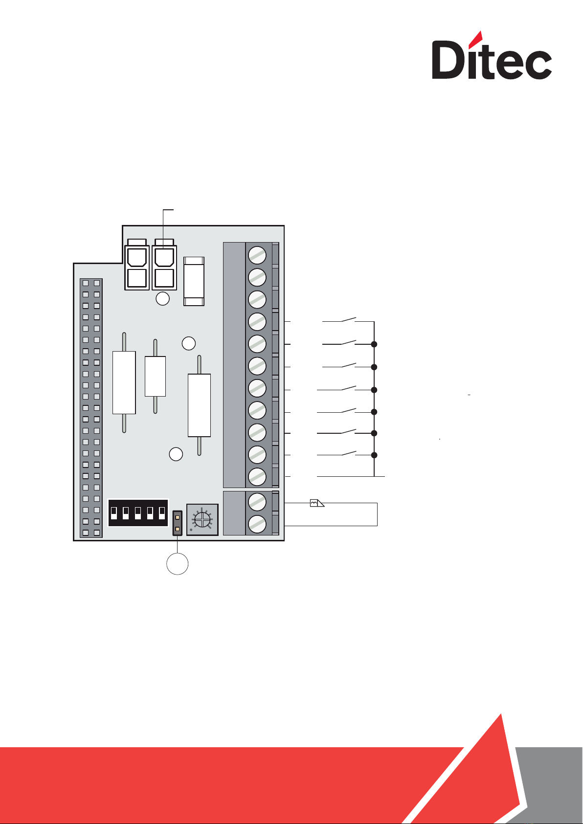
Output Description
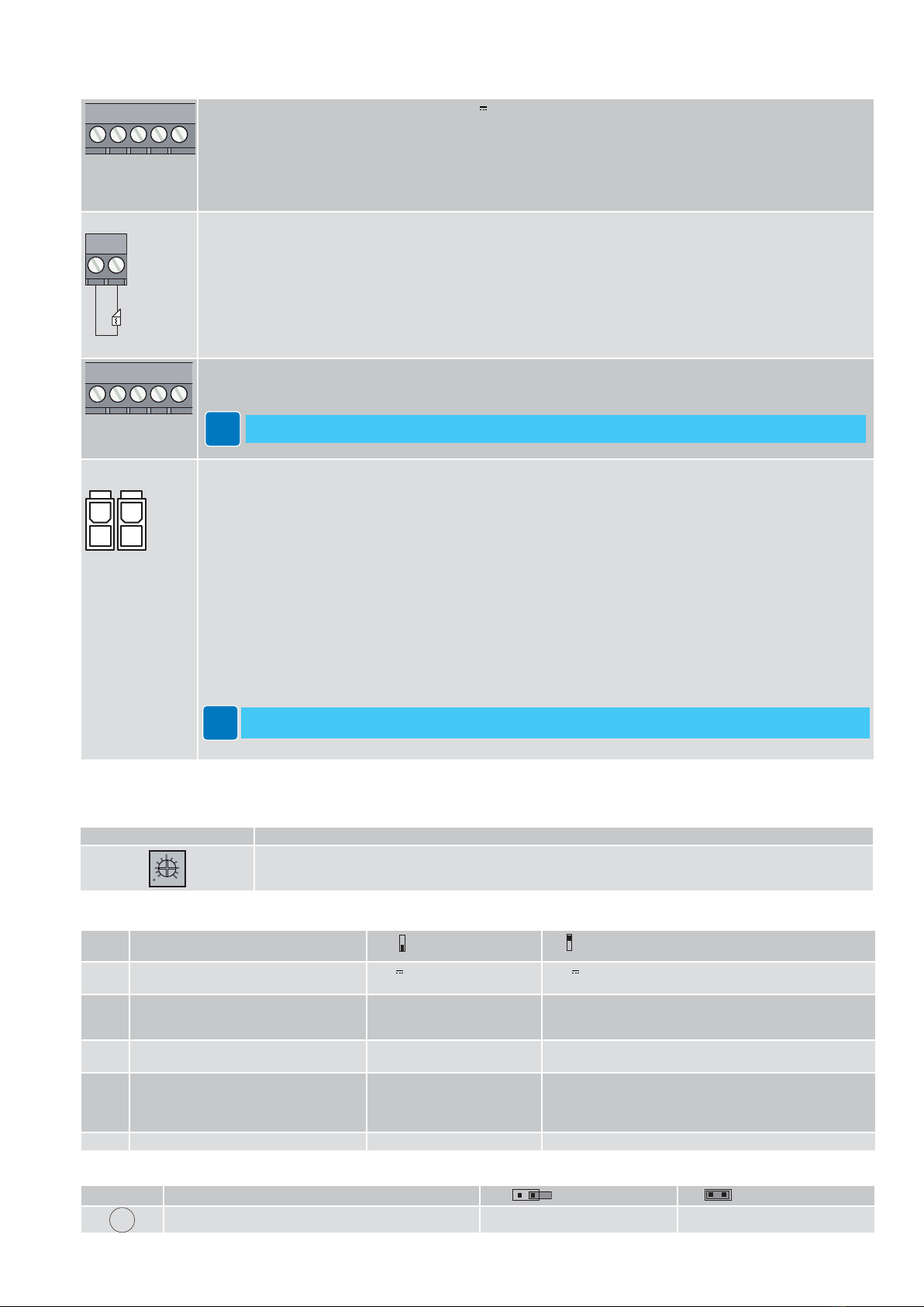
+24V DC
GND
3 ... 13 Output for the power supply to the accessories 24V 400 mA max.
NB: the maximum absorption of 400 mA corresponds to the sum of all the accessories installed.
12
Output for connecting an electric lock / electric strike.
Select the type of power supply using the DIP1 and the type of electric lock / electric strike using the DIP2
With DIP2 in OFF ( electric lock / electric strike Normal), and no COM400MHB/MKB function selector switch (or the latter
in BIDIRECTIONAL mode), output 1-2 is permanently powered = door closed not locked. ( referring status 1 chapter 17.4).
If, on the other hand, you want to lock the door wing with the door closed, set the selector to BIDIRECTIONAL mode or make
a jumper GND-EXIT (3-11). In this condition, output 1-2 is powered throughout the operation from opening until complete
closure; for this reason, locks with mechanical reset cannot be used.
With DIP2 in ON ( electric lock / electric strike Anti-panic), the behaviour will be the same except for the fact that output 1-2
will always be unpowered in BIDIRECTIONAL mode and throughout the open/close operation in MONODIRECTIONAL mode”.
For different setting see Chapter 17.4 Management of electric lock / electric strike power supply.
OPEN
EXIT
OFF
GND
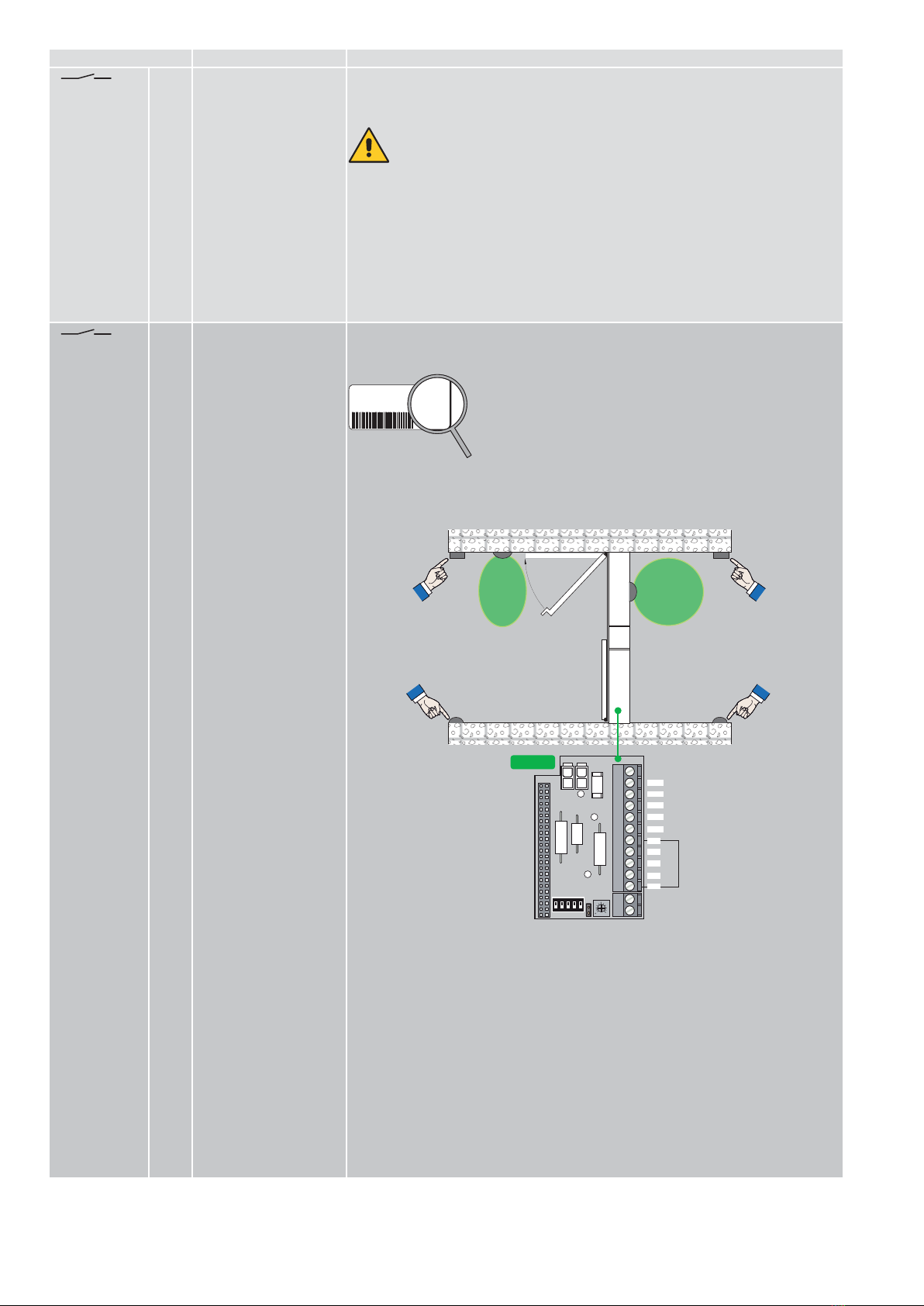
3 ... 10 11 12 Output for connecting the function selector switch.
If the function selector switch is on OFF, the Push and Go function is disabled.
If a function selector switch is installed, disconnect the ON/OFF/HOLD switch (if present).
BATTERY BATTERY KIT
If no mains power supply is available, the battery kit will guarantee operation in "energy-saving" mode.
If no mains power supply is available, the door only operates with the key switch connected to 3 GND -6 KEY.
In “energy-saving” mode, the door can remain stationary for up to a week while waiting for the KEY command.
The following sensors are not active during “energy saving” operation:
-OPD motion sensor
-PIMP reversal safety contact
-PDET opening safety device
In this mode (on automations connected in parallel), connect the batteries only to the MASTER automation fitted with
DAB905ESE.
By changing the pre-configured parameter group, you can set the battery kit to CONTINUITY mode. If no mains power
supply is available, the door operates normally until the batteries are fully discharged.
In this mode, on automations connected in parallel, connect the batteries on both automations equipped with DAB905ESE.
NB: for charging purposes, the battery kit must be connected to the control panel at all times.
A new kit with fully-charged batteries can usually open and close a door consecutively in CONTINUITY mode.
If you want to check the battery kit is working correctly, set DIP5=ON.
In the event of a battery alarm, the DAB105CU control panel LED will flash twice.
i
Monitoring of batteries must always be reset when batteries are replaced. To RESET press and hold the LRN
button while battery mode is active (with mains power supply disconnected).
An acoustic/light alarm signal can be connected to terminals 6-7-8 on the DAB905ESA card.
1.3. Adjustments
1.2 Outputs and accessories
Trimmer
Trimmer Description
Adjustment of the opening delay time, from 0 s to 3 s.
With DIP3=ON, the door release is active throughout the opening delay.
Dip-switches
DIP Description OFF ON
DIP1 Power supply to the electric lock / electric
strike.
12 V max 500 mA 24 V max 250 mA
DIP2 Type of electric lock / electric strike.
DO NOT USE ELECTRIC LOCKS / ELEC-
TRIC STRIKES WITH A RESET FEATURE.
Normal
When it is powered, the door
can be opened.
Anti-panic
When it is unpowered, the door can be opened.
DIP3 Electric lock / Electic strike function Disabled Prior to the opening, a closure thrust is made simultaneous-
ly with the electric lock / electric strike activation impulse.
DIP4 Electric lock / electric strike coupling Disabled Enabled
When it approaches the closing stop, the door increases its
force/speed to ensure correct closure on the electric lock /
electric strike.
DIP5 Battery test Disabled Enabled
Jumper
Description OFF ON
JEmergency closure reset (FIRE BARRIERS ONLY) Manual Automatic
For more information, refer to the COM400MKB-MHB selector manual.
i