DitoGear Trinity User manual

1
Welcome
Thank you very much for purchasing DitoGear™ motion
control equipment. We hope that the devices will meet
your expectations bringing a great value to your productions.
We really strive for delivering the best unboxing and
equipment usage experience. If we (or someone else)
failed at some point, just let us know and we’ll do our
best to fix it promptly.
Here’s where to get started.
» ditogear.com/welcome
More resources
Latest user manuals are available at
» ditogear.com/user-manuals
For advanced connection diagrams check
» ditogear.com/charts
In case you need further assistance contact us at
» ditogear.com/support

2
Quick Start Guide
1. Getting to know the TRINITY
1 Base (A)
2 Rotating arm (B)
3 Product plate (C)
4 Slide plate (D)
5 Angle plate (E)+ Side arm (F),
TRINITY
c
d
e+f
b
a

Quick Start Guide
4
3
5
6
2
1
TRINITY
2. Assembly order
1 Base
2 Rotating arm
3 Product plate
4 Slide plate
5 Side arm
6 Angle plate
2. Preparing the work area
1 Make sure that you have at least 175cm diameter
safe work area with a solid concrete floor
2 Prepare 4 holes for M12 screws
Ø
175c
m
61.2cm
3

4
Quick Start Guide
TRINITY
3. Attaching the Base to the floor
1 Put the Base on a firm and concrete floor
2 Use four M12 screws (included) to attach
the Base to the floor
3 Level the Base using four nuts
0° 0°
3
5
Quick Start Guide
TRINITY
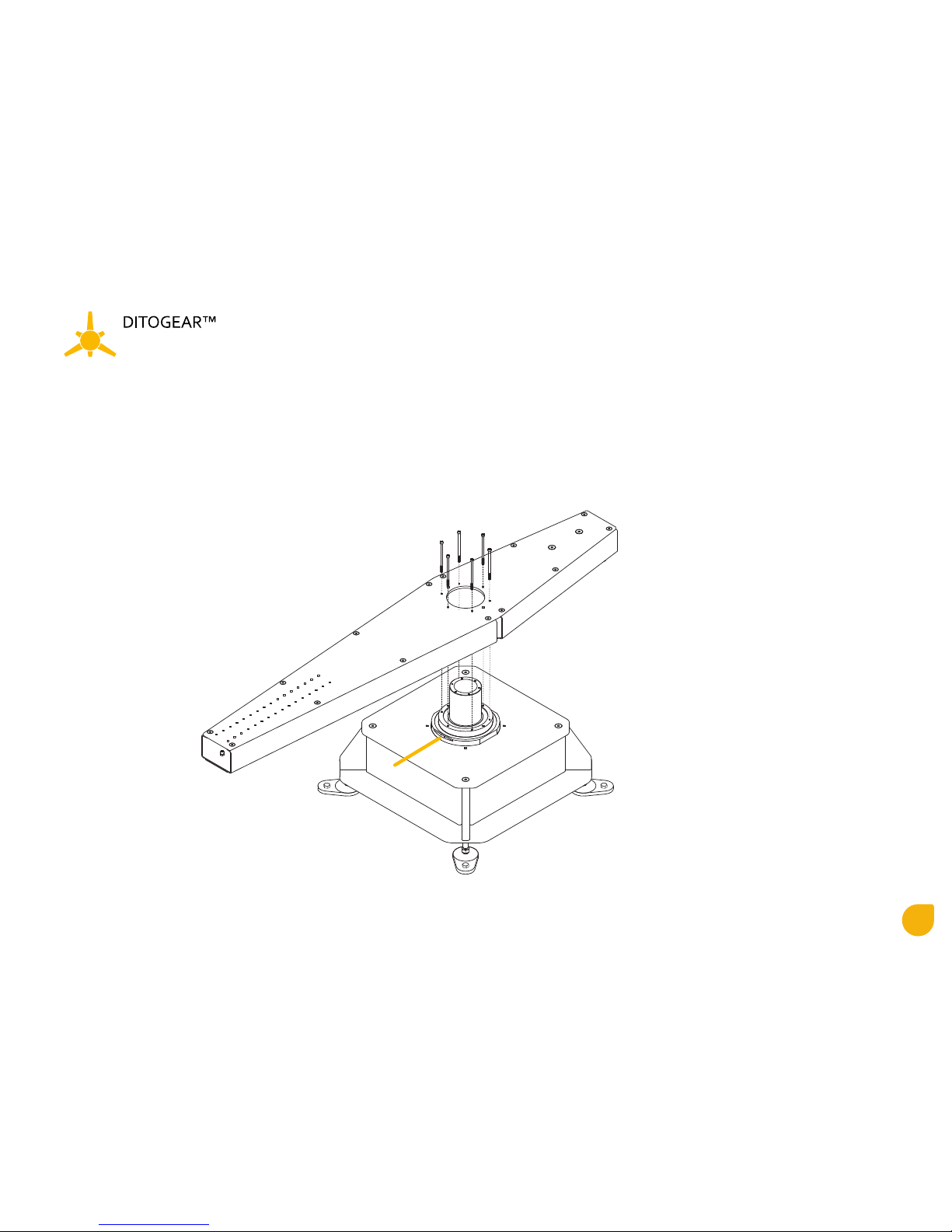
4. Attaching the Rotating Arm to the Base
1 Attach Rotating Arm to the Base.
Point A is a 0° starting point of the Rotating Arm
2 Use six M6 (included) screws and a included
thread glue to screw the Rotating Arm to the Base
a
6
Quick Start Guide
TRINITY
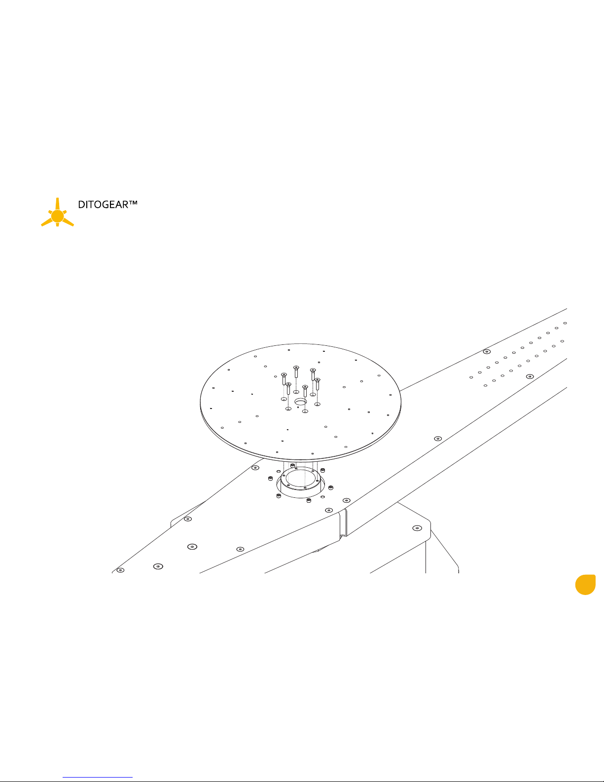
4. Mounting the Product plate
1 Attach Product plate to the Base
2 Use six M6 (included) screws and a included
thread glue to screw the Product plate
to the Base

2
3
1
7
Quick Start Guide
TRINITY
5. Mounting the Slide plate
1 Slide the Slide plate to desire position on the
Rotating Arm
2 Use six M6 (included) screws and a included
thread glue to screw the Slide plate
to the Rotating Arm
3 Tighten the clamping levers
6. Mounting the Side arm
1 Attach the Side arm to the Slide plate on the
desire height
2 Use six M6 (included) screws and a included
thread glue to screw the Side arm to the Slide
plate

8
Quick Start Guide
TRINITY
7. Mounting the Angle plate
1 Attach the Angle plate to the Side arm
2 Use two clamping levers to screw the Angle plate
to the Side arm
8. Using the Angle plate
1 Use lower clamping levers to rotate plate horizontaly
2 Use two side clamping levers to change the angle of the plate,
always use two M6 screws to sustain the angle of the plate.
3 Attach the Camera to the Angle plate using at least two
Camera mounting screws (not included)
1
2
9
Quick Start Guide
TRINITY
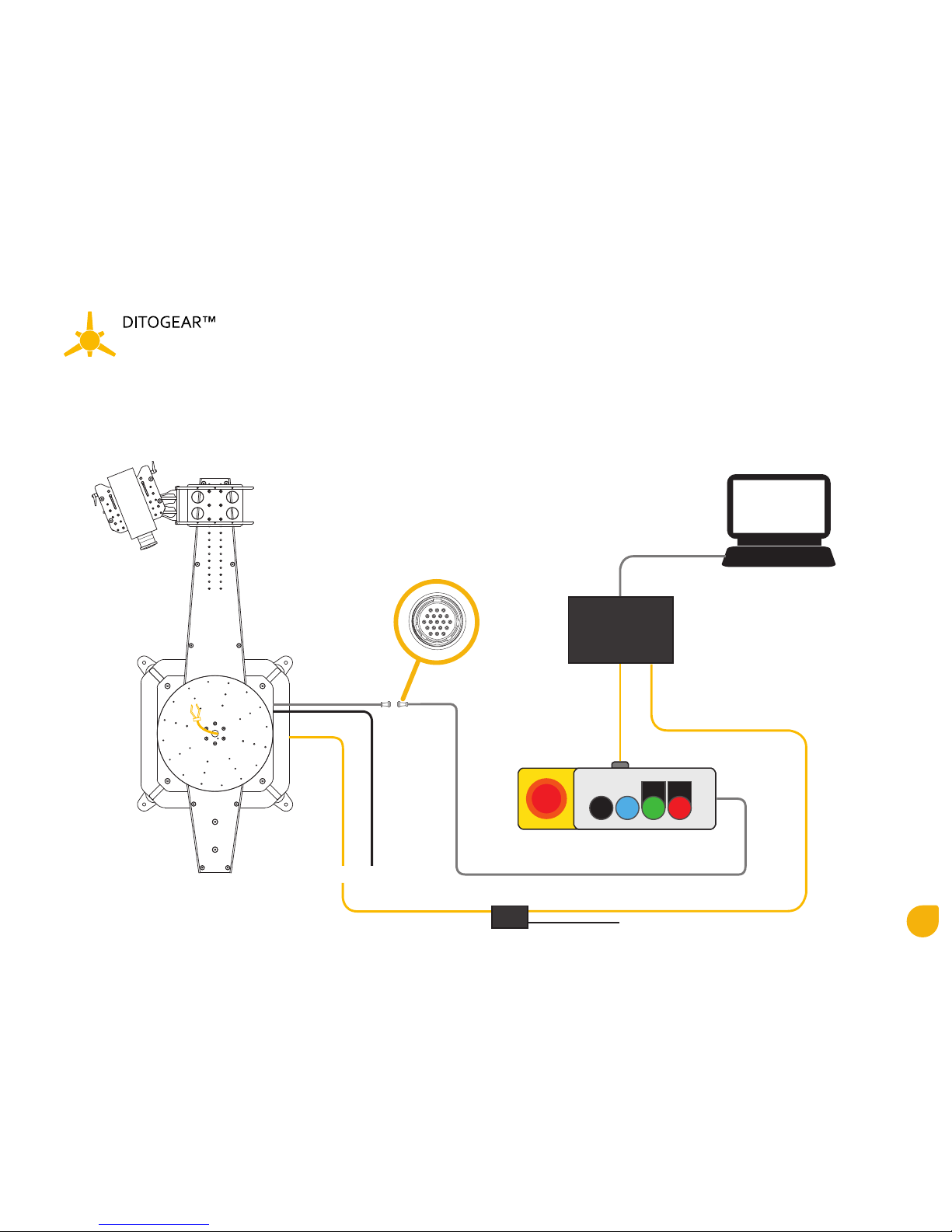
9. Cabling schematic
A - Optional trigger
B - Power input (220v)
C - 19pin data connector
D - Control panel
E - RJ45 cable
F - Speedfire
G - USB cable
H- Laptop/desktop PC
I - Trigger Box
J - Trigger Box
Power input (12v)
A B
C
d
e
F
G
h
i
j
10
Quick Start Guide
TRINITY
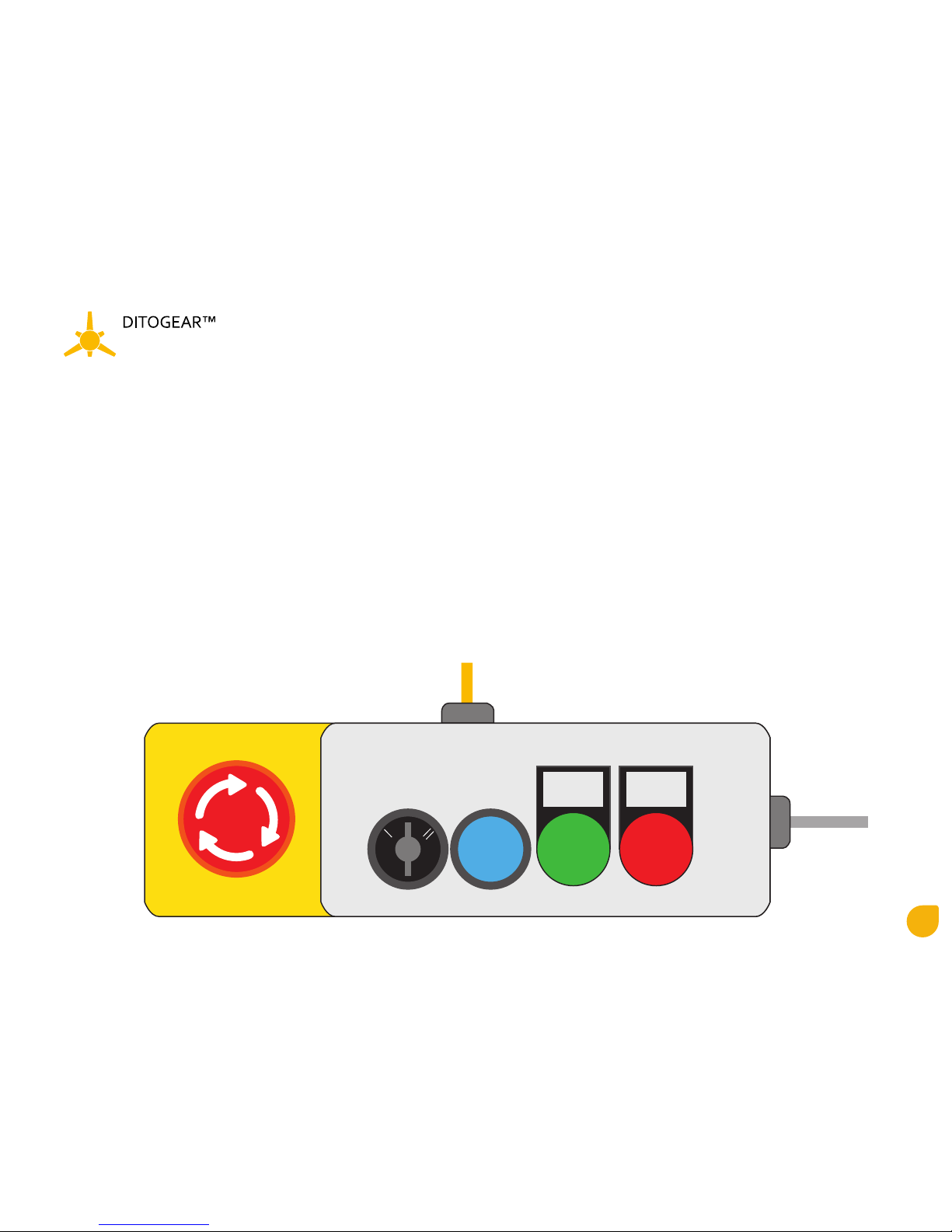
9. Control panel
A - Safety button
- lit up - unit is in operating mode
- in case of an emergency - push the button to cut the power o
(to return to the operating mode, turn the button clockwise)
B - Working mode switch
I - Turned on
0 - Turned o
II - Emergency brake release - to turn the Rotating Arm to the desire position
C - Reset button - to reset the unit after overload
D - Power indicator
E - Alarm indicator (possible overload or other error)
F - 19pin data connector
G - Speedfire cable
R
POWER
0
ALARM
A b c d e
f
g

11
Quick Start Guide
TRINITY
10. Speedfire connectors
Side A
Highspeed RJ45 connectors
AX1 - Trinity
AX2-AX4 - other hispeed units
Triggers RJ45 connectors
AX5 - first group of triggers (contains maximus 3 triggers in series connection)
AX6 - second group of triggers (contains maximus 3 triggers in series connection)
Side B
1 - 12v power input
2 - USB connection to the laptop/desktop PC
A
A
b
b
1
2

12
Quick Start Guide
TRINITY
11. Connecting triggers to the Speedfire via Trigger Box
1. Connect 12v power to power input A. You will hear a beep sound indicating the channel of
this particular unit (1 beep = channel 1, 2 beeps = 2 channel, 3 beeps = channel 3).
To change the channel of the unit, press and hold MODE button F for more than 3 seconds.
Unit have a memory and will remember the channel after plugging the power out.
2. Connect RJ45 cable from SPEEDFIRE unit to (AX5 or AX6) the SIGNAL/BRIDGE connectors
(both sockets are IN/OUT sockets).
3. Connect the trigger to the OUT (mini jack 3.5mm) socket.
4. Now you can adjust the gripper/throttle servo trigger postion with ADJ potentiometer.
Press the MODE button once (1 beep) and adjust the first position of the trigger, confirm
the position by pressing the button again. Now adjust the second position of the trigger
by pressing the button again.
5. Valve triggers don`t have to be adjusted because they are binary (open or closed).
6. If needed connect next trigger box to the SIGNAL/BRIDGE socket with RJ45 cable in serial
connection. One power source (A) works with up to 8 trigger boxes connected to the AX5 or AX6.
A b c
d fe
f
e
d
c
b
A
12345678
A

13
Quick Start Guide
TRINITY
12. SAFETY RULES
1. Prepare a obstacle free working area
at least 1.75m diameter ”safe work area” with any objects and a 6x6m “no entry” area during the operation
2. Always disconnect the power source via Control Panel when you are in safe work area
3. Double check all the screws and loose elements.
4. Be aware that the Rotating Arm is rotating at extreme speeds
and needs a few seconds to stop.
5. Always use safety cables to secure possible elements that can
detach during movement of the Rotating Arm.
6. Ditogear is not liable if and to the extent that
the damage resulted from the misuse of the Ditogear Trinity.
Ø
175c
m
600cm
14
Quick Start Guide
TRINITY
13. Using SPEEDFIRE software on Windows PC
ab
d
c
e
g h i j k l
m n o p r s t u v w x y
f

15
Quick Start Guide
TRINITY
14. Installing SPEEDFIRE software on Windows PC
1. Download latest version of SPEEDFIRE software from Ditogear.com website.
2. There is no need to install the software - it`s a portable, ready to use software.
15. General options - see image at the paragraph 13
A - File
Export to XML - saves parameters and keyframes to the XML file
Import to XML - loads parameters and keyframes from the XML File
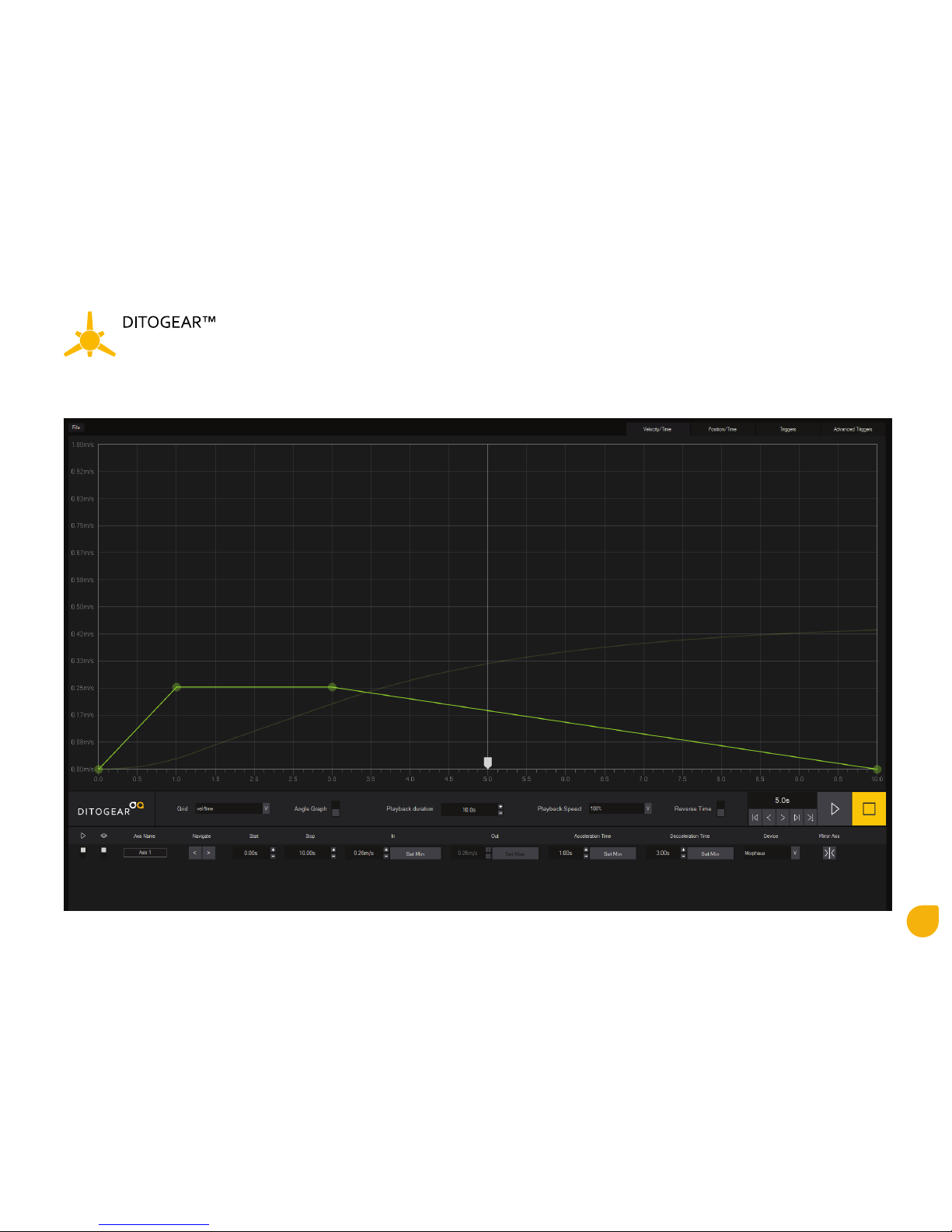
B - Tabs
Velocity/Time - Graph with visual representation of the Rotating Arm velocity during Playback time.
Move the keyframes with a mouse or change parameters in P, R, S, U, V, X
Position/Time - Graph with during Playback time.
Triggers - Activates Triggers panel. Change keyframes of maximum 6 channels of triggers.
Advanced Triggers - Activates Tadvanced triggers panel
C - Graph
Visual representation of the Rotating Arm velocity and position during playback time.
Toggle between vel/time // position/time in F.

16
Quick Start Guide
TRINITY
D - Velocity/Time graph.
Each dot represents the keyframe. Vertical graph axis shows the speed of the arm.
Horizontal graph axis shows time.
1 - First keyframe - time when the Arm starts acceleration
2 - Second keyframe - moment when the Rotating Arm reaches operational speed (shown in S)
3 - Line representing Top speed of the rotation - move it up/down to increase/decrease operational speed of the Arm
4 - Third keyframe - time when the Arm starts deceleration
5 - Fourth keyframe - moment whem the Arm stops
1
2 3 4
5

17
Quick Start Guide
TRINITY
E - Position/Time graph.
The line represents change of the Arm position during time. It`s dependent on the keyframes in Velocity/Time changed
in Velocity/Time graph. Vertical axis shows position of the Arm, Horizontal shows time. You can highlight the line in Position/Time tab at
the top right section of the screen (Paragraph 13.B)
In example below playhead (1) is at 2.1s and at this moment tha Arm will be at 90°. To precisely check the angle at the given time
turn on the Angle Graph (Paragraph 13.H)
1
2 3 4
5
1

18
Quick Start Guide
TRINITY
F - Playhead
It indicates the velocity and position of the Arm during playback. Move the Playhead manualy to get precise info about Position and Time using
Angle Graph (Paragraph 13.H).
G - Grid
Changes the Graph axes fromt vel/time to pos/time
H - Angle Graph
Shows the Angle Graph when user is in Velocity/Time // Position/Time tabs.
1 - visual representation of the position of the Arm at given Time
2 - position of the Arm at given Time . “X” is the number of the full 360° turns of the Arm.
3 - visual representation of the number of the full 360° turns of the Arm.
Each ring represents 360°.
4 - Start/End - range of the movement
I - Playback duration
Duration of the timeline. Maximum time where the keyframes can be adjusted.
J - Playback Speed
Changes speed of the movement and all the keyframes. It don`t aect the graph units.
100% - full speed
75% - 1/3 times slower
50% - 2 times slower
25% - 4 times slower
10% - 10 times slower
5% - 20 times slower
1
2
3
4
h
19
Quick Start Guide
TRINITY
K - Reverse Time
Mirrors the horizontal axis, all keyframes/triggers are played backwards.
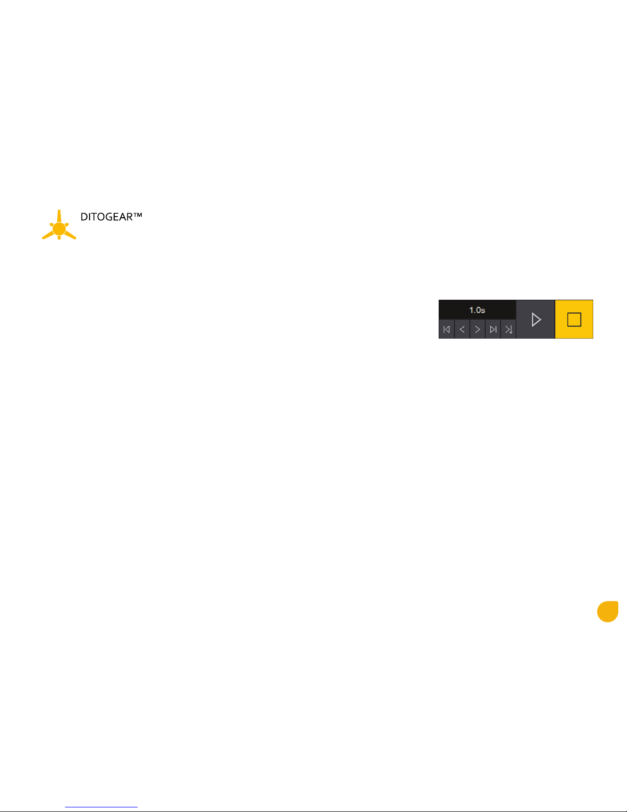
L - Control Panel
1 - time indicator / Playhead position
2 - Start playback
3 - Stop playback
4 - Go to Start
5 - Move Playhead 1s backward
6 - Move Playhead 1s forward
7 - Go to End
8 - Move the Rotation Arm to the Playhead position
M - Active/Inactive Axis
N - Show/Hide Axis (even if it is hide position it still works)
O - Axis name (change by clicking on the name)
P - Function in development (inactive)
R - Position of the first keyframe. Start of the acceleration.
T - Position of the top speed line (D). Change the operation speed of the Rotating Arm.
U - Function in development (inactive)
1 2 3
4 5 6 7 8

20
Quick Start Guide
TRINITY
V - Acceleration Time
Ratio between the first and the second frame. Time of the acceleration.
W - Deceleration Time
Position of the third frame. Moment when the Arm start decelerating.
X - Type of device connected to the Speedfire
Morpheus/Trinity
Y - Mirror Axis
Changes the direction of the rotation from the clockwise to counterclockwise
16. Position/Time Tab (Paragraph 15.B)
Highlights the Position/Time line on the graph.
Table of contents


