manuals.online logo
Brands
  1. Home
  2. •
  3. Brands
  4. •
  5. Nikon
  6. •
  7. Camera Accessories
  8. •
  9. Nikon NAMC User manual

Nikon NAMC User manual

NAMC (Modulation Contrast)
for Ti Series Instructions
•When using this system, be sure to carefully read all precautions in the instruction manual supplied with the microscope.
•NAMC: Nikon Advanced Modulation Contrast
Names of Parts
Figure 1
Notes on Usage
•The name of the condenser lens used in combination with the NAMC module is shown on the top of the module. Use NAMC
or LWD condenser lens. If you use a condenser lens other than the one indicated on the NAMC module being used, the
modulation contrast effect cannot be obtained.
•NAMC module and NAMC objectives are to be used in specific pairs. Always make sure that the NAMC module and NAMC
objective have the same “NAMC code” (NAMC1, NAMC2 or NAMC3). The correct image will not be obtained if the NAMC
codes are different.
•NAMC module is equipped with optical elements made of resin. To clean the NAMC module covered with dust or the like,
lightly blow it off with an air blower. Do not use lens cleaning tissue that could damage the optical elements. Also, avoid using
solvents that may damage the optical elements. Make sure to keep any dirt from coming into contact with the optical
elements during assembly, and especially never to touch them with bare hands.
Assembly
Figure 2
NAMC objective
S Plan FLOUR ELWD
20x (NAMC2)
40x (NAMC3)
Achromat
10x (NAMC1)
20x (NAMC2)
40x (NAMC3)
Clamp ring
(for S Plan FLOUR only)
Modulator ring
Correction ring
(40x only for Achromat)
M519E 09.2.NF.1
Slit aperture rotation gearSlit aperture centering screws
Condenser label
NAMC module
NAMC1, NAMC2, NAMC3
Polarizing filter
NAMC module
(Set inside the system
condenser turret)
Polarizing filter
(Screwed into the top
of condenser mount)
NAMC objective
(Screwed into the
revolving nosepiece)
A
ssemble the microscope.
(Refer to the instruction manual supplied with the
microscope for the assembly.)
*M519EN01*
Microscopy
Hint: Correctly align the slit aperture on the NAMC module to a pattern on the focusing surface of the NAMC objective
(the modulator).
1) Adjust the microscope for the bright-field microscopy. (See the instruction manual supplied with the microscope.)
2) Bring the NAMC 10x objective into the optical path.
3) Rotate the condenser turret to the position “NAMC1”.
4) Fully open the condenser aperture diaphragm.
On modulation contrast microscopy, always fully open the condenser aperture diaphragm to let the enough light pass
through the slit aperture on the NAMC module.
5) Focus on the specimen.
6) Adjust the correction ring on the NAMC objective. (See the instruction manual supplied with the microscope.)
7) Rotate the Bertrand lens in/out lever on the eyepiece tube to the position “B” to bring the Bertrand lens into the optical path.
If your eyepiece tube does not have a Bertrand lens, remove one eyepiece and insert the centering telescope instead.
8) Rotate either the Bertrand lens focusing screw or the eyepiece part on the centering telescope to focus on both the exit
pupil of the NAMC objective (the modulator) and the slit aperture image of the NAMC module.
The view of the modulator
Observe a dark region D at one edge, a narrow gray region G, and a large
bright region B on the exit pupil of the NAMC objective (= modulator).
(Figure 3)
The contrast is attained in the direction shown by the arrow (contrast
direction). Rotate the modulator ring to rotate the modulator so that the
specimen can be observed in good condition. Be careful not to rotate the
correction ring instead of the modulator ring.
The view of the slit aperture image
Observe the two apertures (1) and (2) on the slit aperture image (the
bridge-shaped area (3) is the clearance space between them). Note that
the Part (2) changes the brightness by the rotation of the polarizing filter
on the condenser mount. (There is a polarizing plate set at one side of the
slit aperture: Part (2).)
9) Rotate the slit aperture rotation gear with the tip of the pen or the like,
so that the long direction of the slit aperture image is parallel to the gray
region G on the modulator.
10) Insert two 2 mm hexagonal drivers to the slit aperture centering screw
holes on the NAMC module. (Use the hexagonal drivers supplied with
the Ti Series microscope.)
11) Rotate the hexagonal drivers to move the slit aperture image laterally
till the Part (1) of the slit is registered within the gray region G of the
modulator. (Part (1) does not change its brightness by the rotation of
polarizing filter.)
[Emphasizing the 3D effect on slit aperture image] (Figure 5)
Align the inner edge (a) of the gray region G to that of the slit aperture
image.
Contrast direction
(The contrast is attained in the direction of the arrow.)
Figure 3
Exit pupil of the objective
B: Bright region
D: Dark region
G: Gray region
(2) (1)
Exit pupil of the
objective
Bridge-shaped
area (3)
D
G
Figure 4
(a)
D
G
(1)(2)
(3)
Figure 5
Exit pupil of the
objective
[Controlling light leakage for contrast] (Figure 6)
Align the inner edge (a) of the gray region G on the NAMC objective to the
center of the bridge-shaped area (3).
12) Bring NAMC 20x objective into the optical path. Rotate the condenser turret to the position “NAMC 2”. Perform the above
steps 4) to 11) to set the slit aperture image in correct position.
13) Perform the same adjustments for the NAMC 40x objective and the NAMC 3 module.
Now the microscope is ready for the modulation contrast microscopy.
For using the S Plan FLOUR ELWD objective, you can rotate the modulator ring 360 degrees to set in any desired
position. Also, you can set the clamp ring in the desired position. (For the Achromat objective, however, the rotation is
limited, while no clamp ring is provided.
During the microscopy, note on the following points.
•The NAMC objective and the NAMC module in the optical path must have the same NAMC code.
Table 1 Combination of NAMC objectives and NAMC modules
NAMC Objective NAMC Module
NAMC 10x (NAMC 1) NAMC 1
NAMC 20x (NAMC 2) NAMC 2
NAMC 40x (NAMC 3) NAMC 3
•To obtain a good contrast image, rotate the polarizing filter on the condenser mount.
•Do not turn the slit aperture rotation gear on the NAMC module to adjust the contrast of the image.
•When performing bright-field microscopy using the NAMC objective, rotate the system condenser turret to the position “A
(empty position)”.
(a)
D
(1)(2)
(3)
Figure 6
G
Exit pupil of the
objective
Principles of Modulation Contrast
Since human eyes, cameras, and films capture objects by perceiving differences in light intensity and/or color, they cannot see
(or sense) the colorless, transparent cells or bacteria. These colorless transparent objects are called “phase objects” since they
only change the phase of the light when the light passes through them.
The phase objects can be made visible by dyes, but their life will be deprived. In order to observe the living phase objects,
differential interference contrast and phase contrast microscopy are invented, and modulation contrast microscopy likewise. The
modulation contrast microscopy adopts the same optical system as the ordinary microscopes, but with some additional parts
that convert the transparent specimen into the variation of light intensity. These additional parts modulate the amplitude of the
light that passed through the specimen, thus changing the intensity of the light making up the visible image. (In differential
interference contrast and phase contrast microscopy, the phase objects are converted into the variations of light intensity by the
phase change that occurs when the light passes through the specimen.)
Let’s now think of a light that passes through a specimen. Since a phase object
has the different refractive index than that of its surroundings, the light will be
refracted at its border. (See Figure 7 showing refracted light on trapezoidal phase
object.) The same thing happens to every specimen.
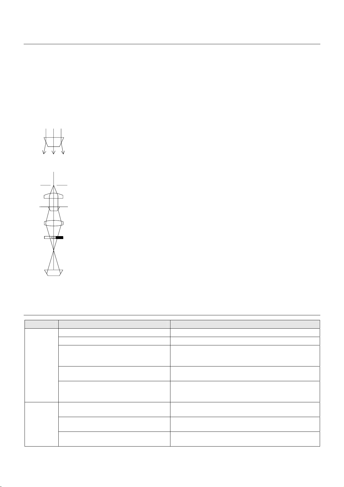
See Figure 8 for the principle of the modulation contrast.
There is a slit diaphragm on the condenser aperture, and modulator inside the
NAMC objective. (The modulator is a density filter placed at the exit pupil of the
NAMC objective. It divides the exit pupil into three regions, dark, half-dark and
transparent.)
If there is nothing on the specimen surface, the light passes through the half-dark
region of the modulator and appears half-dark. If the light is refracted by the phase
object, it passes either the dark or the bright region according to the difference in
the refracted angle. The light then appears dark or bright according to the region
the light passed through. In this way, the phase object is made visible.
In modulation contrast microscopy, the image appears in relief just like the
differential interference contrast microscopy, though its resolution may be a little
inferior. The notable point is that there is no influence of double refraction, thus
enabling you to observe the specimen without double refraction.
Troubleshooting
Problem Cause Countermeasure
No polarizing filter attached. Screw in the polarizing filter to the condenser mount.
No NAMC objectives in the optical path. Use objectives that have “NAMC” indication on its body.
NAMC codes on the NAMC objective and the
NAMC module in the optical path are not the
same.
The NAMC objective and the NAMC module in the optical
path must have the same NAMC code.
Slit aperture image is not correctly aligned to
the gray region on the modulator.
Readjust as described in “Microscopy.”
Poor or dull
contrast
Incorrect condenser position. Set the system condenser firmly on the condenser mount.
Focus the aperture image on the specimen surface and center
it in the viewfield.
Unnecessary filters in the optical path. Remove unwanted filters (ND filters, etc.) from the optical
path.
The DIC analyzer is in the optical path (when
using the DIC attachment at the same time).
Remove the analyzer from the optical path.
Dark Image
Low illumination voltage. Adjust the light intensity control dial to raise the illumination
voltage.
Refer to the instruction manual supplied with the microscope for other troubles than mentioned above.
Figure 7
Figure 8
Phase object
Slit aperture diaphragm
Condenser lens
Specimen
Objective
Modulator
Image
Dark Bright

Other Nikon Camera Accessories manuals

Nikon SB-500 User manual

Nikon

Nikon SB-500 User manual

Nikon FSA-L 1 User manual

Nikon

Nikon FSA-L 1 User manual

Nikon AF Nikkor 50mm f/1.8D User manual

Nikon

Nikon AF Nikkor 50mm f/1.8D User manual

Nikon EN-EL11 User manual

Nikon

Nikon EN-EL11 User manual

Nikon EN-EL2 User manual

Nikon

Nikon EN-EL2 User manual

Nikon f/3.5-5.6G ED VR User manual

Nikon

Nikon f/3.5-5.6G ED VR User manual

Nikon DR-4 User manual

Nikon

Nikon DR-4 User manual

Nikon WP-AA1 User manual

Nikon

Nikon WP-AA1 User manual

Nikon AF-S NIKKOR 300mm f/4E PF ED VR User manual

Nikon

Nikon AF-S NIKKOR 300mm f/4E PF ED VR User manual

Nikon Universal Bracket User manual

Nikon

Nikon Universal Bracket User manual

Nikon DS-L3 User manual

Nikon

Nikon DS-L3 User manual

Nikon AF-S DX NIKKOR 18-300mm f/3.5-5.6G ED VR User manual

Nikon

Nikon AF-S DX NIKKOR 18-300mm f/3.5-5.6G ED VR User manual

Nikon EN-EL5 User manual

Nikon

Nikon EN-EL5 User manual

Nikon SB-22s User manual

Nikon

Nikon SB-22s User manual

Nikon WP-CP4 User manual

Nikon

Nikon WP-CP4 User manual

Nikon D200 User manual

Nikon

Nikon D200 User manual

Nikon AF Nikkor User manual

Nikon

Nikon AF Nikkor User manual

Nikon AF-S NIKKOR 24mm f/1.8G ED User manual

Nikon

Nikon AF-S NIKKOR 24mm f/1.8G ED User manual

Nikon 1 NIKKOR VR 6.7-13mm f/3.5-5.6 User manual

Nikon

Nikon 1 NIKKOR VR 6.7-13mm f/3.5-5.6 User manual

Nikon AF DC-Nikkor 105mm f/2 D User manual

Nikon

Nikon AF DC-Nikkor 105mm f/2 D User manual

Nikon WP-CP2 User manual

Nikon

Nikon WP-CP2 User manual

Nikon DS-L3 User manual

Nikon

Nikon DS-L3 User manual

Nikon WP-N1 User manual

Nikon

Nikon WP-N1 User manual

Nikon HL-E5000 User manual

Nikon

Nikon HL-E5000 User manual

Popular Camera Accessories manuals by other brands

CamRanger PT Hub quick start guide

CamRanger

CamRanger PT Hub quick start guide

Zircon StudSensor L70 OneStep manual

Zircon

Zircon StudSensor L70 OneStep manual

volkano Insta Series instruction manual

volkano

volkano Insta Series instruction manual

Manfrotto 7302YB instruction manual

Manfrotto

Manfrotto 7302YB instruction manual

Filmcity FC-A7RS-Kit Assembly manual

Filmcity

Filmcity FC-A7RS-Kit Assembly manual

Moza Slypod E user manual

Moza

Moza Slypod E user manual

ProMediaGear BH1 instructions

ProMediaGear

ProMediaGear BH1 instructions

Digital Concepts PORTABLE LIGHT STUDIO PS-101 user manual

Digital Concepts

Digital Concepts PORTABLE LIGHT STUDIO PS-101 user manual

Olympus VF-4 instructions

Olympus

Olympus VF-4 instructions

Panasonic HFS1442A operating instructions

Panasonic

Panasonic HFS1442A operating instructions

Riff TL MLV 2 manual

Riff

Riff TL MLV 2 manual

PROAIM P-WNG Setup and operation manual

PROAIM

PROAIM P-WNG Setup and operation manual

Sony TGA-1 operating instructions

Sony

Sony TGA-1 operating instructions

Slide Kamera SP BASIC series user manual

Slide Kamera

Slide Kamera SP BASIC series user manual

GRASS VALLEY CopperHead PowerWafer user guide

GRASS VALLEY

GRASS VALLEY CopperHead PowerWafer user guide

Husqvarna 100-B380X Operator's manual

Husqvarna

Husqvarna 100-B380X Operator's manual

Olympus FCON-T02 instructions

Olympus

Olympus FCON-T02 instructions

PowerTech SB2220 instruction manual

PowerTech

PowerTech SB2220 instruction manual

manuals.online logo
manuals.online logoBrands
  • About & Mission
  • Contact us
  • Privacy Policy
  • Terms and Conditions

Copyright 2025 Manuals.Online. All Rights Reserved.