manuals.online logo
Brands
  1. Home
  2. •
  3. Brands
  4. •
  5. DIVERSITECH
  6. •
  7. Security Sensor
  8. •
  9. DIVERSITECH Wet Switch WS-1 User manual

DIVERSITECH Wet Switch WS-1 User manual

Other DIVERSITECH Security Sensor manuals

DIVERSITECH ASURITY Wet Switch WS-1 User manual

DIVERSITECH

DIVERSITECH ASURITY Wet Switch WS-1 User manual

DIVERSITECH WS-1 User manual

DIVERSITECH

DIVERSITECH WS-1 User manual

Popular Security Sensor manuals by other brands

Honeywell Home PROSiXCOCN Installation and setup guide

Honeywell Home

Honeywell Home PROSiXCOCN Installation and setup guide

Duevi SIRPZ-RB-868 Operation

Duevi

Duevi SIRPZ-RB-868 Operation

RKI 65-2483RK Operator's manual

RKI

RKI 65-2483RK Operator's manual

Nortech PD160 Enhanced Series user manual

Nortech

Nortech PD160 Enhanced Series user manual

Omron K8AC-H2 manual

Omron

Omron K8AC-H2 manual

Agilent Technologies G8610 Series Quick reference card

Agilent Technologies

Agilent Technologies G8610 Series Quick reference card

Shinko SE2EA-1-0-0 instruction manual

Shinko

Shinko SE2EA-1-0-0 instruction manual

Det-Tronics X Series instructions

Det-Tronics

Det-Tronics X Series instructions

ACR Electronics COBHAM RCL-300A Product support manual

ACR Electronics

ACR Electronics COBHAM RCL-300A Product support manual

TOOLCRAFT 1712612 operating instructions

TOOLCRAFT

TOOLCRAFT 1712612 operating instructions

Elkron IM600 Installation, programming and functions manual

Elkron

Elkron IM600 Installation, programming and functions manual

Bosch WEU PDO 6 Original instructions

Bosch

Bosch WEU PDO 6 Original instructions

THORLABS PDA10JT user guide

THORLABS

THORLABS PDA10JT user guide

Waeco UV-DETECT operating manual

Waeco

Waeco UV-DETECT operating manual

Intermatic IOS-DSIMF manual

Intermatic

Intermatic IOS-DSIMF manual

Siemens AZL66 Series manual

Siemens

Siemens AZL66 Series manual

BTI Profiline Multi Finder operating instructions

BTI

BTI Profiline Multi Finder operating instructions

Challenger SL01 instruction manual

Challenger

Challenger SL01 instruction manual

manuals.online logo
manuals.online logoBrands
  • About & Mission
  • Contact us
  • Privacy Policy
  • Terms and Conditions

Copyright 2025 Manuals.Online. All Rights Reserved.

PUSH
TO
TEST
PUSH
TO
RESET
WETSWITCH
®
Flood
Detector
AUX CONTACTS:
5A 250V
D
I
V
E
R
S
I
T
E
C
H
C
O
R
P
O
R
A
T
I
O
N
•
D
U
L
U
T
H
,
G
A
C
O
N
F
O
R
M
S
T
O
U
L
S
T
D
5
0
8
M
O
D
E
L
N
O
.
W
S
-
1
POWER ON MOISTURE
CLASS II CIRCUIT
2.0 AMPS
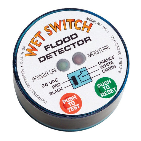
Wet Switch prevents ooding and property damage by detecting
moisture caused by accumulation of air-conditioning condensate, drain
leaks, etc. When moisture is detected, the normally closed circuit
controlling the system is disconnected. An additional circuit is included,
normally open, that may be used to operate an alarm device as well.
Multiple Wet Switches may be connected in series (within the electrical
limits of the power supply), to expand coverage area. Wet Switch
incorporates isolated relay contacts, for added exibility in installations
with electronic control boards where breaking one lead from the
transformer is not possible.
Status Indications & Operation
Normal State: When power is applied and no moisture is
detected, the “POWER ON” LED will be lit green, and the
“MOISTURE” LED will be OFF.
Pressing the red “TEST” button simulates moisture detection and
conrms proper function of Wet Switch. “MOISTURE” LED will be lit
red, & “POWER” LED will be OFF.
Press the green “RESET” button to return Wet Switch to normal state.
When moisture is detected, the control circuit is opened, and the
“MOISTURE” LED is lit red. Wet Switch will remain in this state until the
problem is corrected and the “RESET” button is pressed, or power is
disconnected. Aer correcting the moisture problem, & with power
disconnected, use a clean, absorbent cloth to thoroughly dry the
sensor pad on the bottom of Wet Switch. Any residual moisture in
the pad may cause a false detection. A warm air device (such as
a hair drier on low heat ONLY) may be used to help dry the pad.
Installation
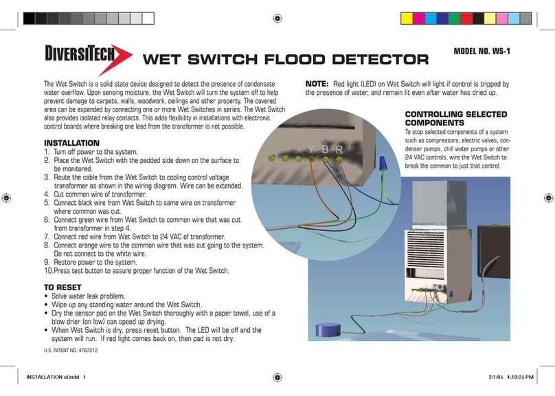
1. Turn o power to the system.
2. Place Wet Switch, padded side down, on the surface to be monitored.
3. Connect wiring as shown in the diagrams on page 2. Wires may be
extended as necessary, but avoid excess run lengths.
4. Restore power to the system.
5. Press “TEST” to assure proper function.
Controlling Selected Components
System components such as compressors, electric valves, condenser
pumps, chill water pumps, or other 24 VAC controls may be connected
selectively and independently to Wet Switch.
Model No. WS-1
WET SWITCH®FLOOD DETECTOR
LED Indicators
Wet Switch
Schematic
TEST & RESET
Buttons
POWER IN
24VAC
WS-1
EQUIPMENT
(THERMOSTAT,
CONTROL
BOARD, etc.)
BLACK
GREEN
RED
ORANGE
WHITE ALARM
(option)
(Normally
open)
Typical Wet Switch Connection:
(Bold dashed lines indicate eld wiring)
Two or More Wet Switches in Series:
Moisture detection by either switch interrupts the circuit
(Normally
closed)
WET SWITCH SPECIFICATIONS
LED INDICATORS:
Green: Power On, Normal State
Red: Moisture Detected
POWER REQUIREMENTS:
24 VAC, 50/60 Hz
1.5 Watts max (wet), <0.5 Watts (dry)
RELAY:
Isolated Contacts:
Normally Closed - 5 Amps (max) @ 250 V
Normally Open - 5 Amps (max) @ 250 V
RED
BLACK
RED
BLACK
POWER IN
24VAC
EQUIPMENT
(THERMOSTAT,
CONTROL
BOARD, etc.)
BLACK
RED
WHITE ALARM
(option)
(Not
connected)
RED
BLACK
RED
BLACK
BLACK
RED
WHITE
(Normally
open)
GREEN ORANGE
(Normally
closed)
WS-1
GREEN ORANGE
(Normally
closed)
WS-1
1-800-995-2222
www.diversitech.com
DOC00036
Dashed lines indicate eld wiring