DIY-Thermocam V2 User manual

Revision 5 from 12.09.2017
1.
• To assemble the device, you need the following tools: A soldering iron, some
solder, a cutting pliers, a nippers, a screwdriver and a multimeter
• At the moment, the following versions of the FLIR Lepton sensor are supported:
2.0 (80x60), 2.5 (80x60 radiometric) & 3.0 (160x120)
• If you have the choice between multiple soldering tips, use the smallest one
• In case you have a soldering station with adjustable temperature, use around 400
- 450 degree celcius
• Catch the PCB, the microcontroller and one of the two pin header strips
• Cut the header strip with a cutting pliers into the following pieces: 2 x 15, 1 x 5 and
3 x 1
DIY-Thermocam V2 Assembly Guide
Page 1DIY-Thermocam V2 Assembly Guide
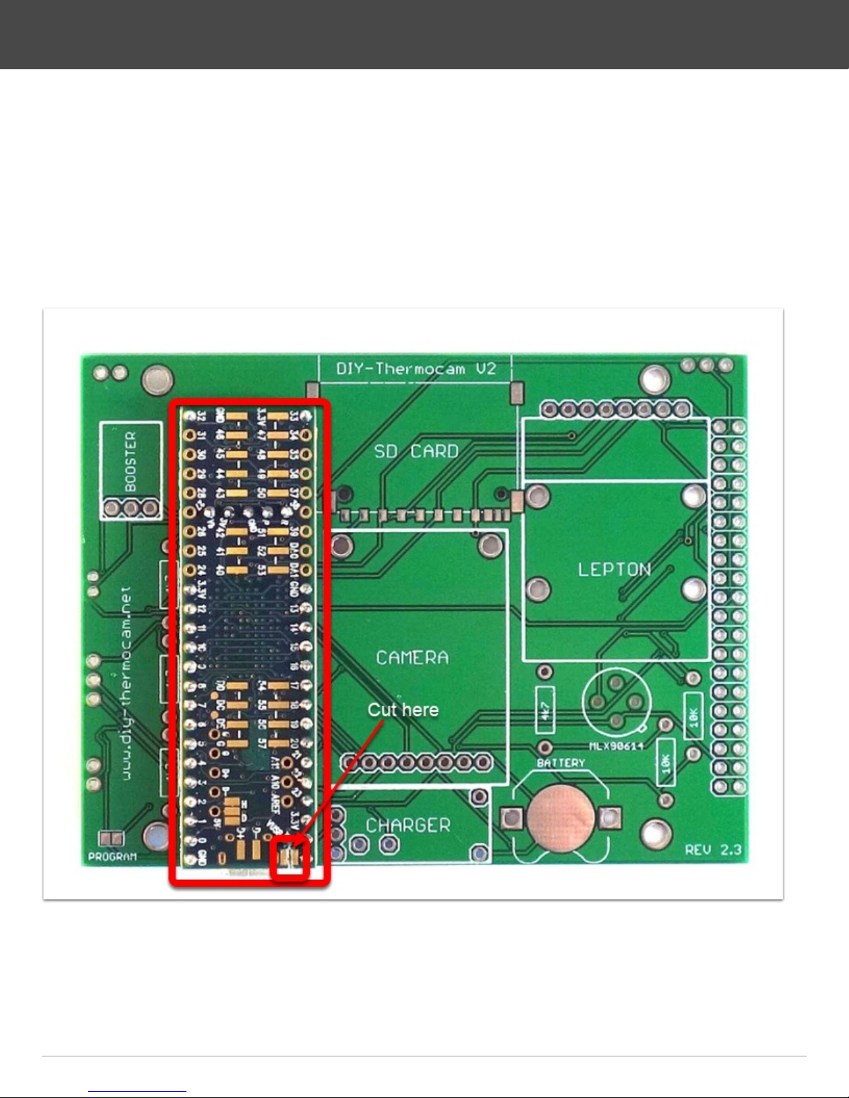
2.
• Plug the microcontroller into the header pieces
• One of the three single header should be placed in the hole labeled VUSB, do not
forget it
• Put the microcontroller with the headers into the PCB and make sure they sit tight
• Solder the pins on top of the microcontroller
• Cut the trace between VUSB and VIN on the microcontroller with a sharp knife
DIY-Thermocam V2 Assembly Guide
Page 2DIY-Thermocam V2 Assembly Guide

3.
• Turn the PCB around, make sure the microcontroller still sits tight
• Solder the pins on the bottom
• Cut the pins short with cutting pliers, right above the solder points you just made
• Re-solder the pins to make sure they are really connected well to the PCB
DIY-Thermocam V2 Assembly Guide
Page 3DIY-Thermocam V2 Assembly Guide

4.
• Attach the SD card slot to the PCB by soldering the four points on the edges first,
then the data pins on the bottom side
• Put the 8GB micro SD card into the SD adapter
• Put the adapter into the SD card slot
DIY-Thermocam V2 Assembly Guide
Page 4DIY-Thermocam V2 Assembly Guide
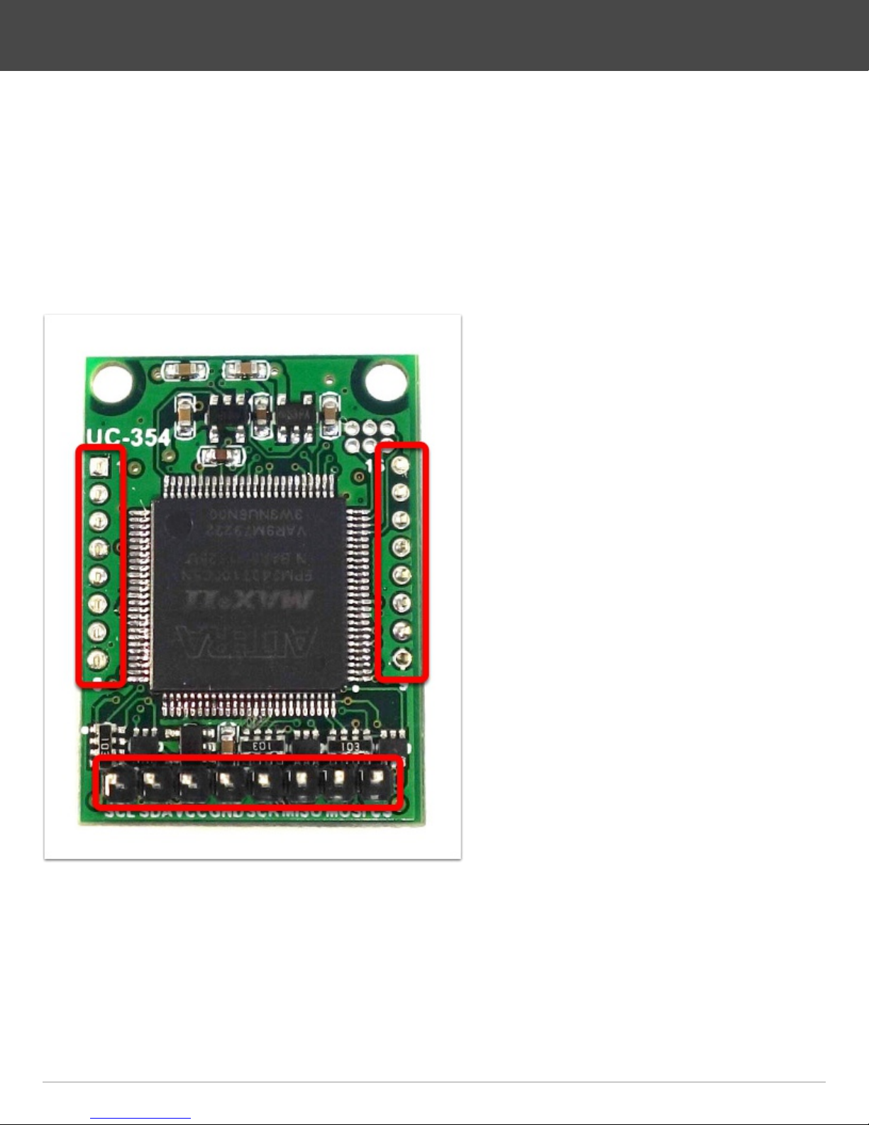
5.
• Remove the wifi shield from the backside of the visual camera module
• Push the two female sockets on the two sides alternating to the left and right, until
they drop off
• It's required to break those pieces off, otherwise the module will not fit later
• Use the 8-pin female header socket to bend the 8-pin male header on the bottom
of the module into a straight position
DIY-Thermocam V2 Assembly Guide
Page 5DIY-Thermocam V2 Assembly Guide
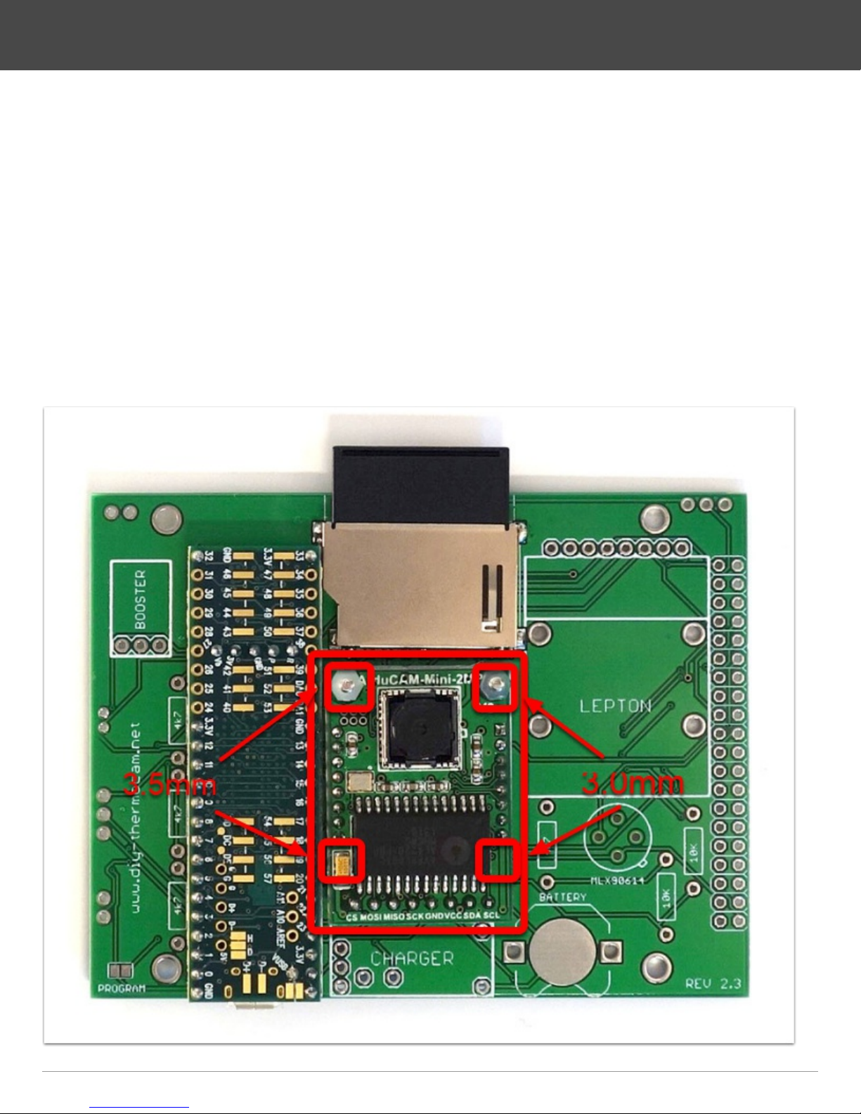
6.
• Use two of the M2 x 10 bolts and put them though the holes in the PCB
• On the left bolt, put one of the M2 x 3.5mm distance spacers, on the right bolt one
of the M2 x 3.0mm spacer, take care you choose the right length
• Put the visual camera module on top of the bolts, push the header into the PCB
and save it with two M2 plastic nuts
• Use the remaining M2 x 3.5mm spacer and put between the module and the PCB
on the left position marked, then use a M2 x 3.0mm spacer and put it on the right
side
• Push the module against the PCB, then solder the 8-pin header on the backside
and cut the pins short with cutting pliers
DIY-Thermocam V2 Assembly Guide
Page 6DIY-Thermocam V2 Assembly Guide
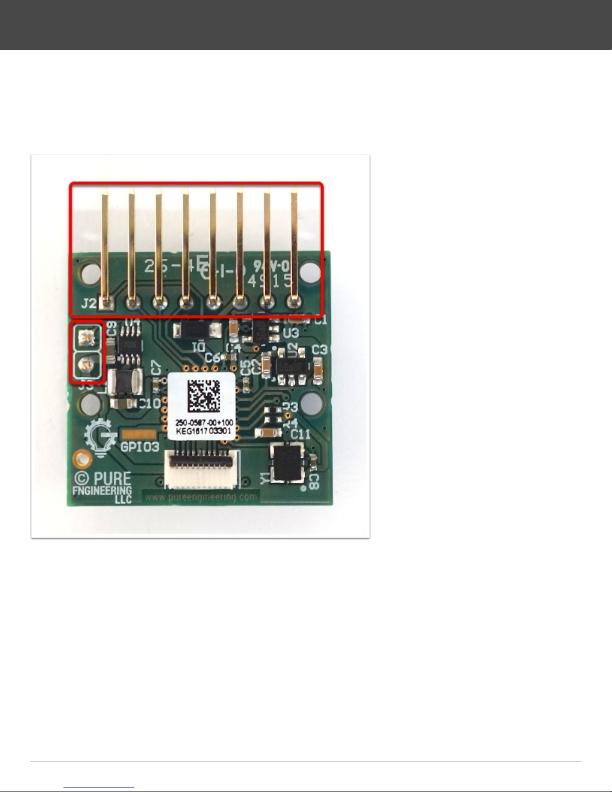
7.
• Remove the plastic part from the angled male pins with your hand or a nippers
• Bend the 2-pin header alternating to the left and the right, until it drops off
DIY-Thermocam V2 Assembly Guide
Page 7DIY-Thermocam V2 Assembly Guide

8.
• Grab the 8-pin right-angle female header and put it into the PCB
• Use two M2x10 bolts and put one of the 3.0mm black spacers on top of each
• Plug the Lepton board into the socket and through the two bolts, then save it with
two plastic nuts
• Pick up two more M2x10 bolts and put them into the empty holes on the top, then
save them with plastic nuts
• Use two more smaller black spacers and put them between the PCB and the
Lepton module on the marked position, as they do not fit on the bolts
• Solder the female header to the PCB and cut the pins short with cutting pliers
DIY-Thermocam V2 Assembly Guide
Page 8DIY-Thermocam V2 Assembly Guide
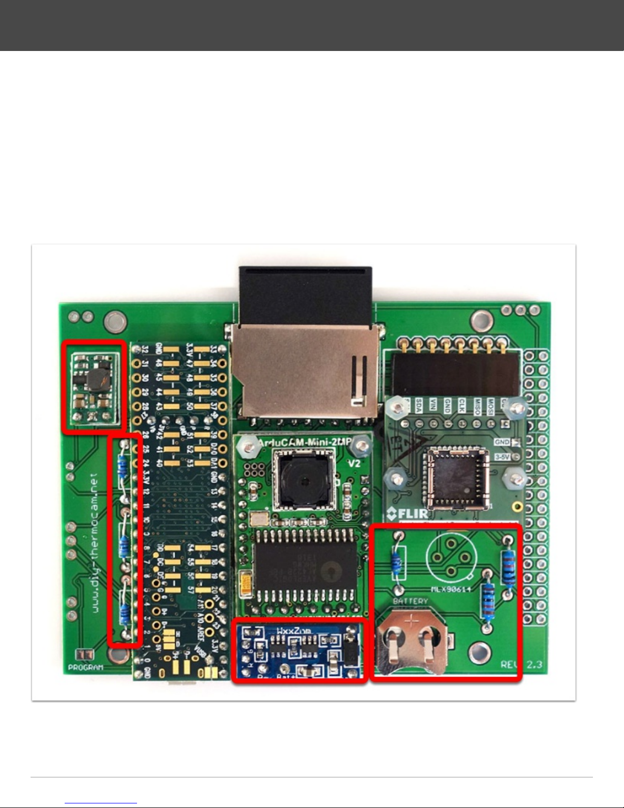
9.
• Solder the step-up converter to the PCB by using a 3 pin strip
• Solder the four 4.7k resistors (the smaller ones) to their position on the PCB
• Solder the two 10k resistors (bigger ones) to their position right to the spot sensor
• Solder the charging module to the PCB by using a pin strip together with four
single ones
• Cut the pins short on the backside with cutting pliers
• Solder the coin cell battery holder to the PCB
DIY-Thermocam V2 Assembly Guide
Page 9DIY-Thermocam V2 Assembly Guide
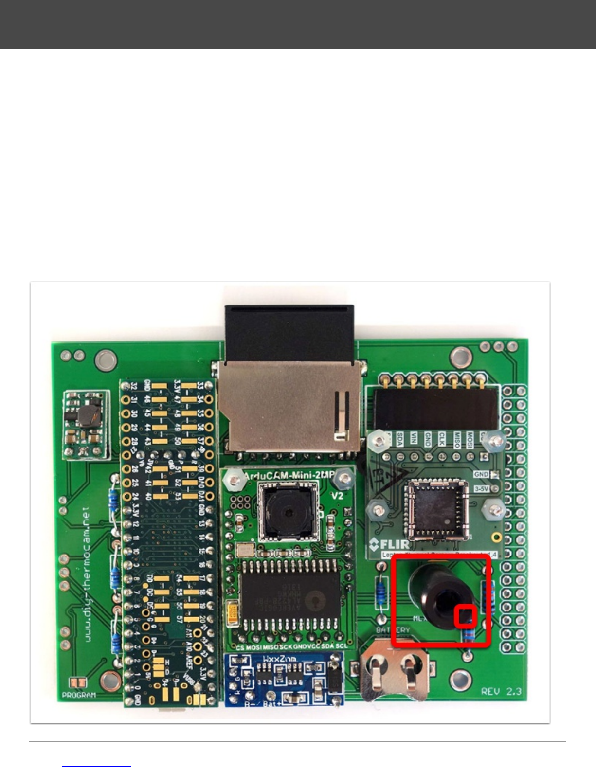
10.
• Check your FLIR Lepton version: Lepton2.0 (80x60, non-radiometric), Lepton2.5
(80x60, radiometric), Lepton3.0 (160x120, non-radiometric) and skip this step 10 if
you have the Lepton2.5
• Catch the MLX90614 single-point infrared sensor and plug it into the board, make
sure the little indicator matches the mark on the PCB
• Solder one pin first on the backside, then push the sensor against the board while
heating the solder on the same pin to make sure that the sensor is really soldered
flat to the board
• Solder the remaining three pins on the backside
• Cut the pins short with a cutting pliers
DIY-Thermocam V2 Assembly Guide
Page 10DIY-Thermocam V2 Assembly Guide
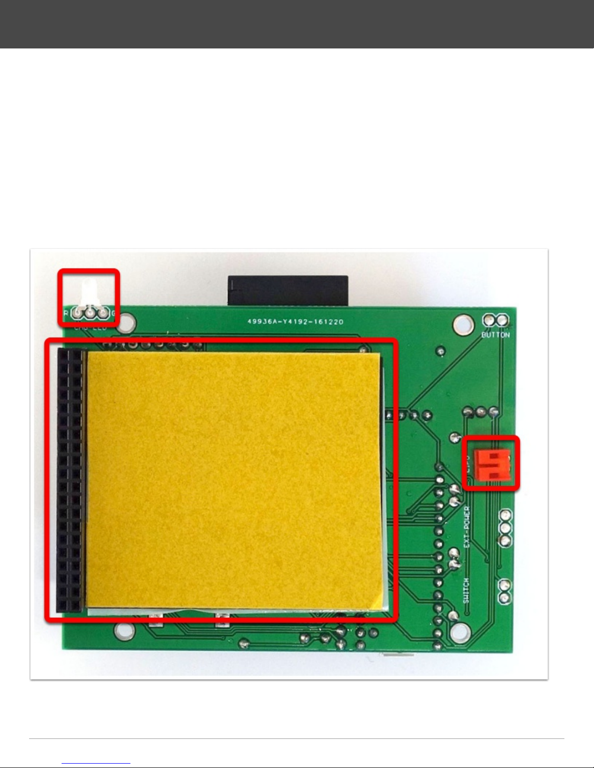
11.
• Put the charging LED to the place labeled CHG-LED with the short leg in the hole
G
• You can put it all the way in, then bend the LED to the top as shown on the image
and solder it
• Solder the battery connector to the place labeled LIPO on the right side
• On the left side, solder the display connector in the 40 holes, make sure it really
sits tight
• Attach the adhesive tape for the lithium battery
DIY-Thermocam V2 Assembly Guide
Page 11DIY-Thermocam V2 Assembly Guide
12.
• Grab the the six side panels from the enclosure and remove the protection foil
from both sides
• For all enclosure parts, the shiny side goes inside, whereas the matted side goes
to the outside
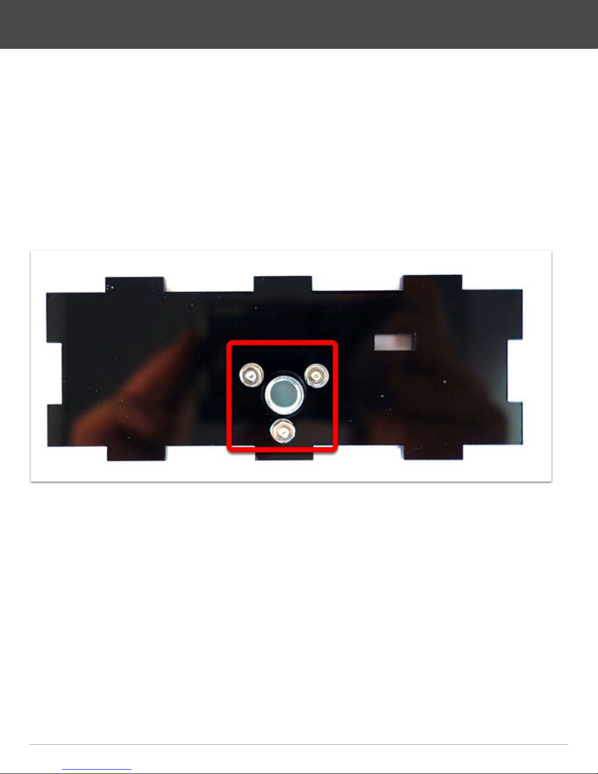
• Get the bottom panel and hold it so that the shiny side is looking towards you
• Fix the tripod socket like shown with three M2 x 8 bolts, three washers and nuts
and screw them very tight
• Make sure that the round plate of the socket is on the outside (matted side)
DIY-Thermocam V2 Assembly Guide
Page 12DIY-Thermocam V2 Assembly Guide
13.
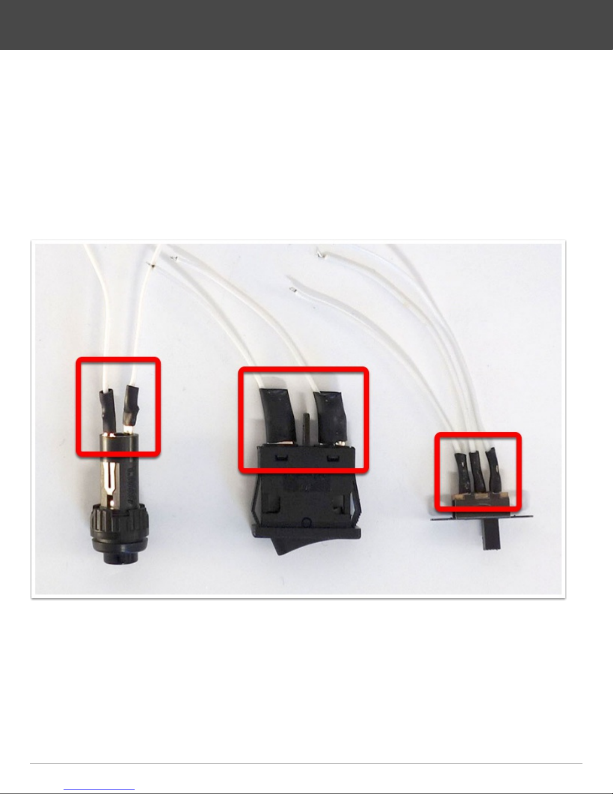
• Take the push button, the power switch and the external USB switch together with
the shrink tubes and the cable pieces
• Solder the cable pieces to the components
• It is good to put some solder on the components pins first, then on the cables, and
afterwards put those two together
• Put shrink tubes on top of the connection places on the cables and heat them with
a soldering iron
DIY-Thermocam V2 Assembly Guide
Page 13DIY-Thermocam V2 Assembly Guide

14.
• Put the position of the power switch to OFF (O) and push it through the hole in the
panel
• Secure the USB power switch with two M2 x 8 bolts and two nuts, then switch it to
the upper position as shown on the image
• On the other panel, put the button into the other side of the sidepanel and safe it
with the screw ring
DIY-Thermocam V2 Assembly Guide
Page 14DIY-Thermocam V2 Assembly Guide
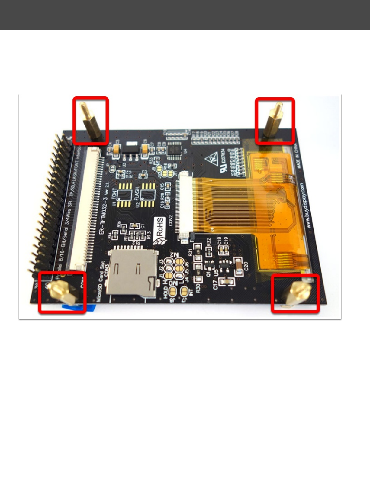
15.
• Pick the display module and screw the four smaller distance bolts into the four
bigger ones
DIY-Thermocam V2 Assembly Guide
Page 15DIY-Thermocam V2 Assembly Guide
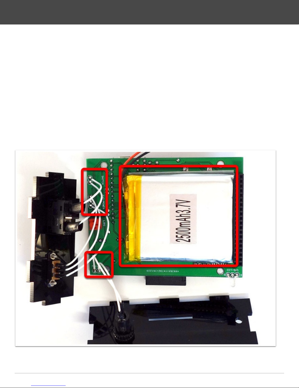
16.
• Put the lithium battery in place like shown on the image, but do not connect it so
far
• Solder the wires of the push button to the two pins labeled BUTTON, the direction
does not matter. It is good to put some solder on the pins first, then on the cables,
and afterwards put those two together
• Next, solder the wires of the power switch to the two pins labeled SWITCH, the
direction does not matter
• Lastly, solder the three wires of the external USB switch to the connection labeled
EXT-POWER
• Take care to keep the chronology order, so top to top, middle to middle, bottom to
botttom
DIY-Thermocam V2 Assembly Guide
Page 16DIY-Thermocam V2 Assembly Guide
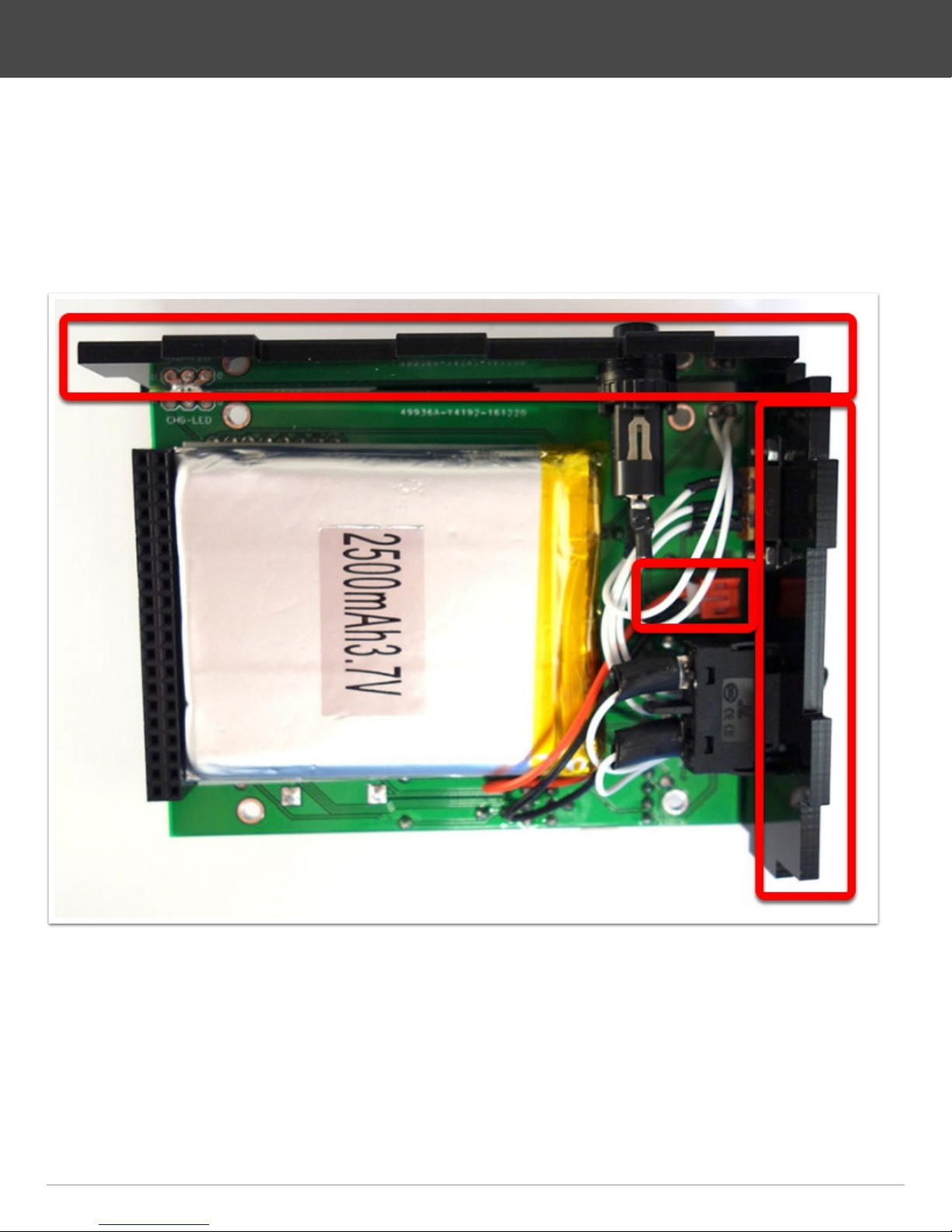
17.
• Make sure the power switch is still in the off-position, then connect the battery
cable to the red terminal marked
• Put the two sideplates to their position and bend the wires, so that they do not put
the display under pressure later
DIY-Thermocam V2 Assembly Guide
Page 17DIY-Thermocam V2 Assembly Guide
18.
• Put the display module on top of the PCB and safe it with the four remaining
distance bolts
• Screw them into the PCB as shown on the image and tighten them
• Insert the Lepton 2.0, 2.5 or 3.0 into the module, make sure you hear a click when
it snaps in
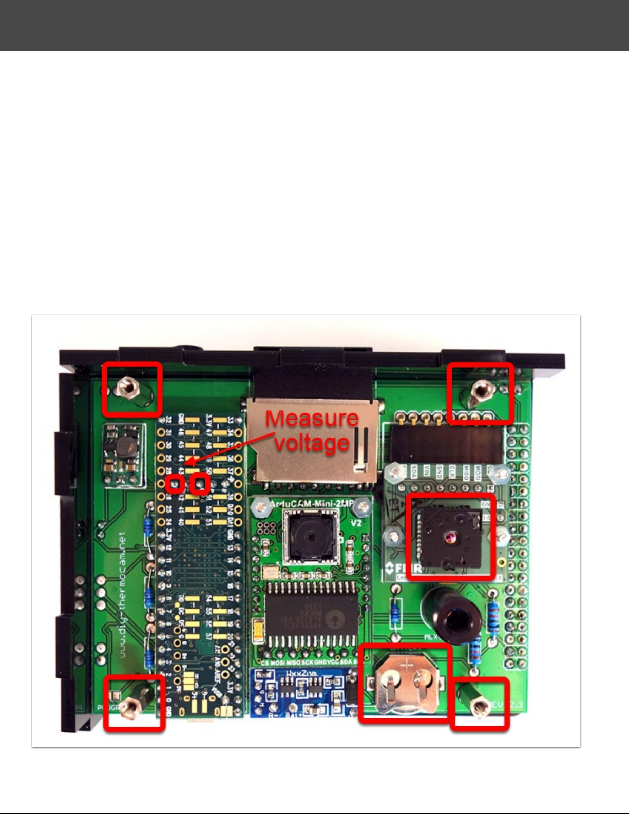
• Insert the coin cell battery into the holder, so that the side with the +-marker is on
the top
• Check with a multimeter, if the voltage between the pin labeled "VBAT" (battery)
and "GND" (ground) is above or equal to 3V
• If this is not the case, move the battery inside the holder a little bit, until you can
measure the voltage on the two pins
DIY-Thermocam V2 Assembly Guide
Page 18DIY-Thermocam V2 Assembly Guide
19.
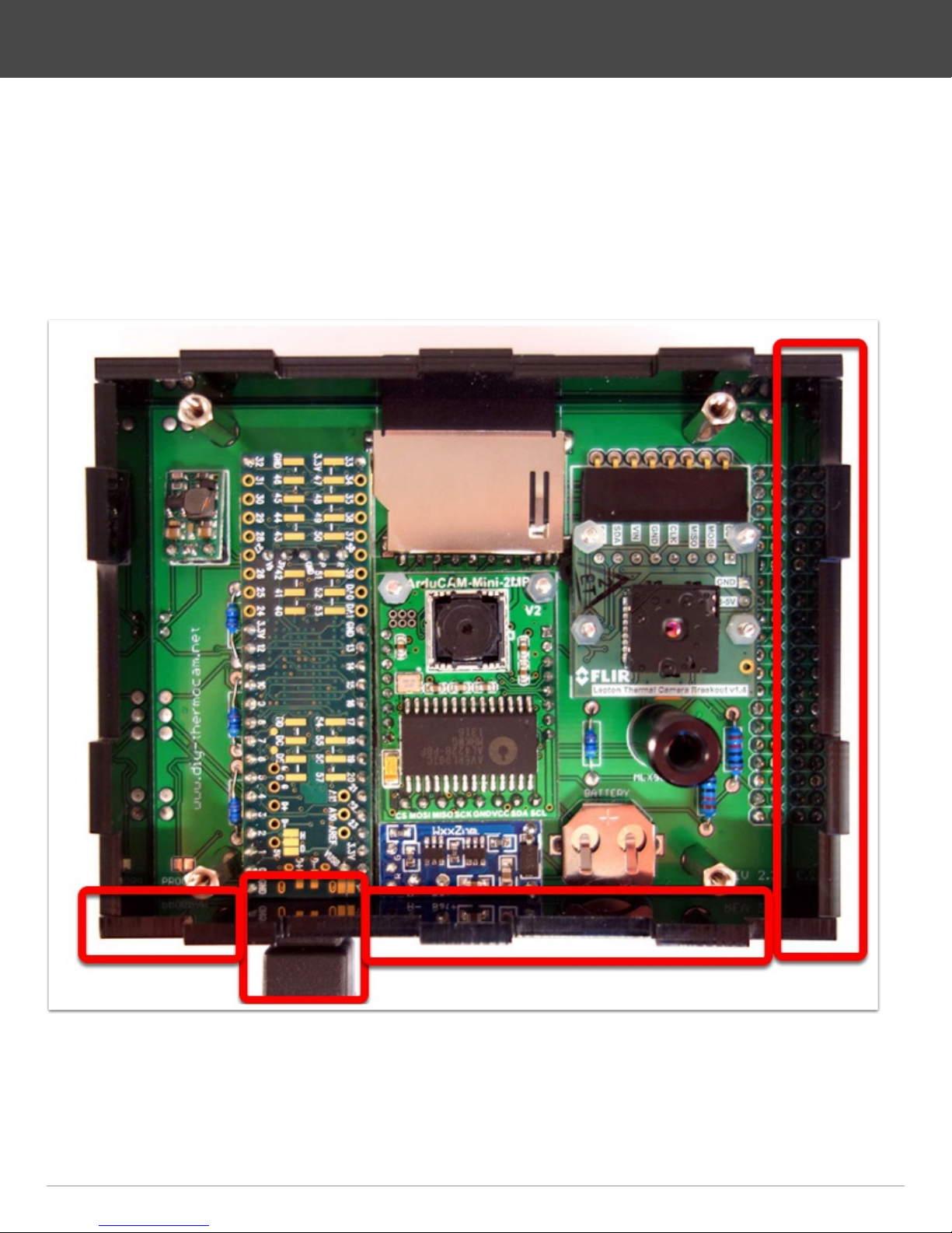
• Install the display panel (top side) and afterwards the right and bottom sidepanel
• It makes a difference how they are inserted, so take care the matted side is on the
outside and they are rotated right to fit
• Make sure that the microUSB connector of the microcontroller snaps into the hole
of the bottom sidepanel
DIY-Thermocam V2 Assembly Guide
Page 19DIY-Thermocam V2 Assembly Guide

20.
• Put the backpanel on top of the four sidepanels and secure it with four of the black
screws
• It may be a little bit tricky to make it fit the first time, do not use more pressure than
required
DIY-Thermocam V2 Assembly Guide
Page 20DIY-Thermocam V2 Assembly Guide


