djm direct DJMBAS80 User manual

Band Saw
Item No.:DJMBAS80
Band Saw
Original Operating Manual

1
1.Introduction
MANUFACTURER:
DJM Direct.com
Unit 43 Churchill Way,
Lomeshaye Industrial Estate,
Nelson, Lancashire BB9 6RT UK
DEAR CUSTOMER
We hope your new tool brings you much enjoyment
and success.
NOTE:
According to the applicable product liability laws, the
manufacturer of the device does not assume liability
for damages to the product or damages caused by the
product that occurs due to:
●Improper handling,
●Non-compliance of the operating instructions,
●Repairs by third parties, not by authorized service
technicians,
●Installation and replacement of non-original spare
parts, .
●Application other than specified,
WE RECOMMEND:
Read through the complete text in the operating
instructions before installing and commissioning the
device. The operating instructions are intended to help
the user to become familiar with the machine and take
advantage of its application possibilities in accordance
with the recommendations. The operating instructions
contain important information on how to operate the
machine safely, professionally and economically, how
to avoid danger, costly repairs, reduce downtimes
and how to increase reliability and service life of the
machine.
In addition to the safety regulations in the operating
instructions, you have to meet the applicable
regulations that apply for the operation of the machine
in your country. Keep the operating instructions
package with the machine at all times and store it in a
plastic cover to protect it from dirt and moisture. Read
the instruction manual each time before operating
the machine and carefully follow its information. The
machine can only be operated by persons who are
instructed concerning the operation of the machine
and who are informed about the associated dangers.
The minimum age requirement must be complied
with. In addition to the safety requirements in these
operating instructions and your country’s applicable
regulations, you should observe the generally
recognized technical rules concerning the operation of
woodworking machines.
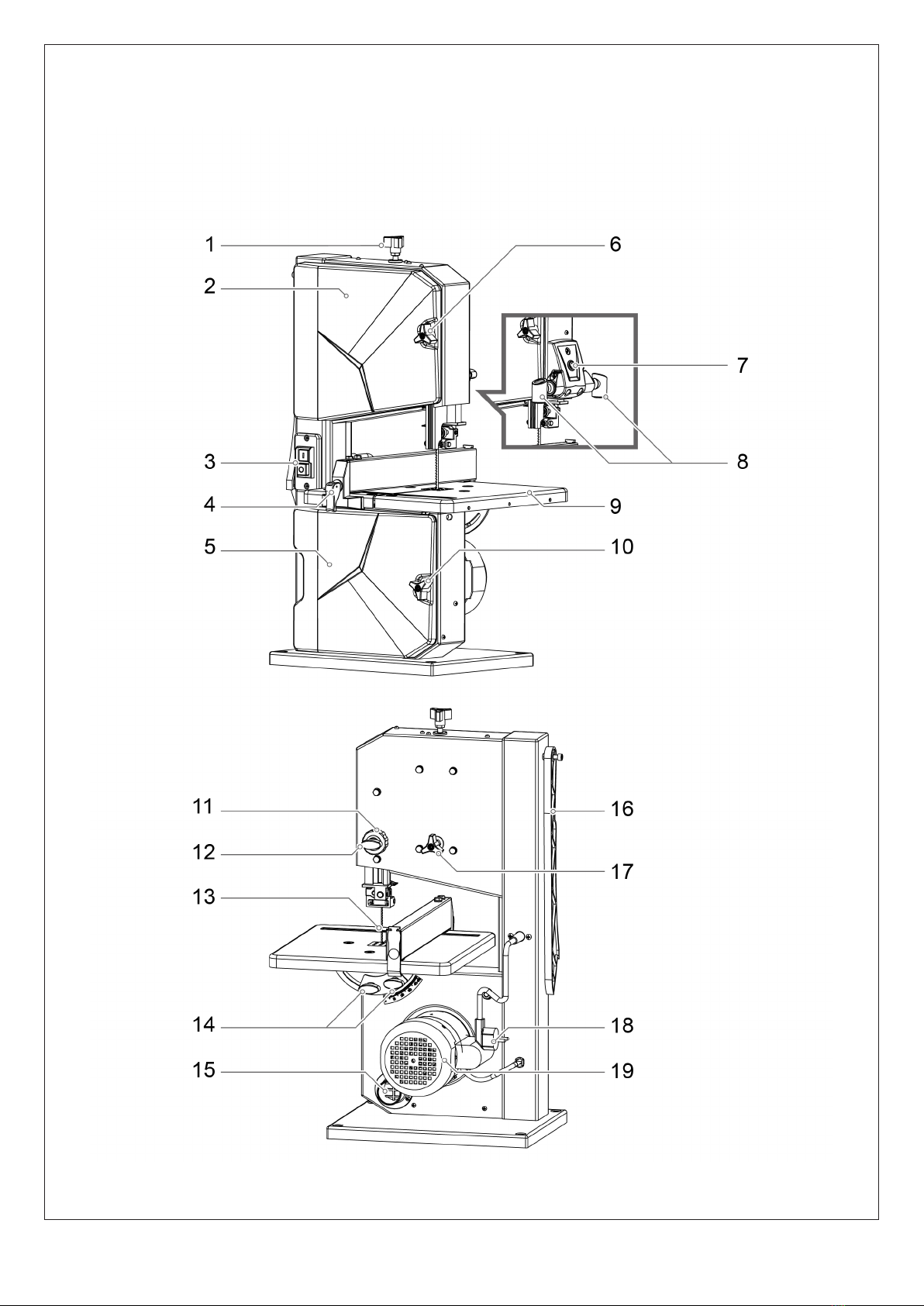
2.Device Description
1. Setting Knob for Blade Tension
2. Upper Housing Door
3. ON/OFF Switch
4. Rip Fence
5. Lower Housing Door
6. Door Lock
7. ON/OFF Switch for Lamp
8. Lamp (65160A Only)
9. Work Table
10. Door Lock
11. Setting Knob for Blade Guard
12. Locking Knob for Blade Guard
13. Blade
14. Setting Knob for Work Table
15. Suction Connector
16. Push Stick
17. Setting Knob for Blade Tracking
Adjustment
18. Power Cord and Plug
19. Motor
2

3
3. Unpacking
●Open the packaging and remove the device carefully.
●Remove the packaging material as well as the
packaging and transport bracing (if available).
●Check if the delivery is complete.
●Check the device and accessory parts for transport
damage.
●If possible, store the packaging until the warranty
period has expired.
ATTENTION
The device and packaging materials are not toys!
Children must not be allowed to play with plastic
bags, film and small parts! There is a risk of
swallowing and suffocation!
4. Safety
a) General Safety Rules
Understand your Machine
Read this manual and labels affixed to the machine to
understand its limitations and potential hazards.
Be thoroughly familiar with the controls and their
proper operation. Know how to stop the machine and
disengage the controls quickly.
Do not attempt to operate the machine until you fully
understand how to properly operate and maintain
the engine and how to avoid accidental injuries and/or
property damage.
If the unit is to be used by someone other than original
purchaser or loaned, rented, or sold, always provide
this manual and any needed safety training before
operation. The user can prevent and is responsible for
accidents or injuries that may occur to themselves,
other people, and property.
Do not force the machine. Use the correct machine for
your application. The correct machine will do the job
more efficiently and safer at the rate it was designed.
Personal Safety
Do not permit children to operate this machine at any
time.
Keep children, pets, and other people not using the
unit away from the work area. Be alert and shut off
unit if anyone enters work area. Keep children under
the watchful care of a responsible adult.
Do not operate the machine while under the influence
of drugs, alcohol, or any medication that could affect
your ability to use it properly.
Dress properly. Wear heavy long pants, boots, and
gloves. Do not wear loose clothing, short pants, or
jewelry of any kind. Secure long hair so it is above
shoulder level. Keep your hair, clothing, and gloves
away from moving parts. Loose clothes, jewelry, or
long hair can be caught in moving parts.
safety glasses with side shields when operating.
Protect eyes, face, and head from objects that may be
thrown from the unit. Always wear safety goggles or
safety glasses with side shields when operating.
Wear appropriate hearing protection. Wear respiratory
protection to avoid the risk of inhaling harmful dust.
Always keep hands and feet away from all moving
parts during operation. Moving parts can cut or crush
body parts.
Always keep hands and feet away from all pinch
points.
Do not touch parts that might be hot from operation.
Allow parts to cool before attempting to maintain,
adjust, or service.
Stay alert, watch what you are doing, and use common
sense when operating the machine.
Do not overreach. Do not operate the machine
while barefoot or when wearing sandals or similar
lightweight footwear. Wear protective footwear that
will protect your feet and improve your footing on
slippery surfaces. Keep proper footing and balance at
all times. This enables better control of the machine in
unexpected situations.
Inspect your Machine
Check your machine before starting it. Keep guards in
place and in working order. Make sure all nuts, bolts,
etc., are securely tightened.
Never operate the machine when it is in need of
repair or is in poor mechanical condition. Replace
damaged, missing, or failed parts before using it.
Keep the machine in safe working condition. Regularly
check to see that keys and adjusting wrenches are
removed from the machine area before starting it. A
wrench or a key that is left attached to a rotating part
of the machine may result in personal injury. Avoid
accidental starting. Be sure the motor switch is off
before transporting the machine or performing any
maintenance or service on the unit.
Transporting or performing maintenance or service on
a machine with its switch on invites accidents. If the
machine should start to vibrate abnormally, stop the
motor and check immediately for the cause. Vibration
is generally a warning sign of trouble.
Electric Safety
Protect yourself from electric shock. Do not plug or
unplug the motor while standing in or around damp
or wet ground. Do not use the unit in wet or damp
areas or expose it to rain. Prevent body contact with
grounded surfaces: pipes, radiators, ranges, and
refrigerator enclosures. Make sure your fingers do
not touch the plug’s metal prongs when plugging or
unplugging the unit.
Avoid inadvertent starting. Make sure that the switch
is switched off when plugging the plug into an outlet.
Only use approved and appropriately identified
extension cables for use outdoors. Only use cable reels
in the unrolled state.

4
Do not use the cable for purposes for which it is not
intended. Do not use the cable to pull the plug out of
the outlet. Protect the cable from heat, oil and sharp
edges.
Have your electric tool repaired by a qualified
electrician. This electric tool conforms to the
applicable safety regulations. Repairs may only be
performed by an electrician using original spare parts.
Otherwise accidents can occur.
Work Area & Store Area
Keep the work area orderly. Disorder in the work area
can lead to accidents.
Take environmental influences into account. Do not
expose electric tools to rain. Do not use electric tools
in a damp or wet environment. Make sure that the
work area is well-illuminated. Do not use electric tools
where there is a risk of fire or explosion.
Securely store unused electric tools. Unused electric
tools should be stored in a dry, elevated or closed
location out of the reach of children.
b) Specific Safety Rules
Intended Use
The band saw is designed to perform longitudinal and
cross cuts on timber or wood-type materials. To cut
round materials you must use suitable holding devices.
The equipment is to be used only for its prescribed
purpose. Any other use is deemed to be a case of
misuse. The user / operator and not the manufacturer
will be liable for any damage or injuries of any kind
caused as a result of this. The machine is to be
operated only with suitable saw blades. To use the
machine properly you must also observe the safety
regulations, the assembly instructions and the
operating instructions to be found in this manual. All
persons who use and service the machine have to be
acquainted with this manual and must be informed
about the machine’s potential hazards.
Machine Use
The manufacturer shall not be liable for any
changes made to the machine nor for any damage
resulting from such changes. The following
hazards may arise in connection with the
machine’s construction and design:
● Harmful emissions of wood dust when used in
closed rooms.
● Contact with the blade in the uncovered cutting
zone.
● Injuries (cuts) when changing the blade.
● Injury from catapulted workpieces or parts of
work-pieces.
● Crushed fingers.
● Kickback.
● Tilting of the workpiece due to inadequate
support.
● Touching the blade.
● Take care of your tools. Keep cutting tools sharp
and clean in order to be able to work better and more
safely. Follow the instructions for lubrication and
for tool replacement. Check the connection cable of
the electric tool regularly and have it replaced by a
recognized specialist when damaged. Check extension
cables regularly and replace them when damaged.
Keep the handle dry, clean and free of oil and grease.
Residual Risks
Despite proper use, additional residual risks cannot
be completely ruled out. The following risks may arise
due to the nature of the Band saw:
Mechanical hazards related to:
Machine parts or workpieces:
• Shape
• Relative location
• Mass and velocity (kinetic energy of elements in
controlled or uncontrolled motion)
• Cutting or severing hazard
• Entanglement hazard
Electrical hazards due to:
• Contact of persons with live parts (direct contact)
• Contact of persons with parts which have become
live under faulty conditions (indirect contact)
• Electrostatic phenomena
Hazards generated by noise, resulting in:
• Hearing loss (deafness), other physiological
disorders (loss of balance, loss of awareness)
• Interference with speech communication, acoustic
signals.
Hazards generated by materials and substances (and
their constituent elements)
processed or used by the machinery
• Hazards from contact with or inhalation of harmful
fluids and dusts
• Fire hazard
Hazards generated by neglecting ergonomic principles
in machinery design related to:
• Unhealthy postures or excessive effort
• Hand-arm or foot-leg anatomy
• Local lighting
• Mental overload and underload, stress
• Human error, human behaviour
• Design, location or identifiation of manual controls
Combination of hazards
Unexpected start up, unexpected overrun/ overspeed
(or any similar malfunction) from:
• Failure/disorder of the control system
• External influences on electrical equipment
• Errors made by the operator (due to mismatch of
machinery with human
characteristics and abilities)

5
2
1
6
9
5
7
8
11
9
A
B
4
3
10
• Impossibility of stopping the machine in the best
possible conditions
• Variations in the rotational speed of tools
• Failure of the power supply
• Failure of the control circuit
• Errors of fitting
• Break-up during operation
• Falling or ejected objects or fluids
• Loss of stability / overturning of machinery
5. Technical Data
Technical Data
Specifications:
Mains Voltage : 240V/50Hz
Power : 250W
Throat Capacity : 195 mm
Max. Cutting Height : 80 mm @ 90°
45 mm @ 45°
Blade Wheel Dia. :205 mm
Blade Length :1400 mm
Blade Width: 3.5-12 mm
Cutting Speed :950 m/min
Table Size :302×304 mm
Table Tilt: 90° - 45°
6. Contents Supplied
The band saw comes partially assembled and is
shipped in carefully packed carton. After all the
parts have been removed from the carton, you
should have:
1. Main Machine
2. Push Stick
3. Work Table
4. Rip Fence
5. Table Insert
6. Operator’s Manual
7. Allen Key, 4mm
8. Allen Key, 3mm
9. Blade Key
10. Lamp
11. Hardware Bag

6
9. Machine Use and Care
-Do not use low-output electric tools for heavy work.
Do not use the electric tool for purposes for which it
is not intended. For example, do not use Band Saw for
the cutting of branches or logs. Do not use the electric
tool to cut firewood.
-When the saw blade is blocked due to abnormal
feed force during cutting, turn the machine off and
disconnect it from power supply. Remove the work
piece and ensure that the saw blade runs free. Turn
the machine on and start new cutting operation with
reduced feed force.
-Do not remove any cutting residues or other parts of
workpieces from the cutting zone while the machine is
running and the saw unit is not at rest.
Never remove loose splinters, chips or jammed pieces
of wood while the saw blade is running.Switch off the
machine to troubleshoot or remove jammed pieces of
wood.
-Do not begin cleaning the blade until it has
come to a complete standstill.Wear safety gloves
whenever you carry out any maintenance work on the
blade!
-When cutting round or irregularly shaped wood, use
a device to stop the workpiece from twisting.Ensure
that the choice of blade and the selected speed
are suitable for the material to be cut.
-When cutting boards in upright position, use a device
to prevent kick-back.
-A dust extraction system designed for an air velocity
of 20 m/s should be connected in order to comply
with woodworking dust emission values and to ensure
reliable operation.
-If you use a cable reel, the complete cable has to
be pulled off the reel.
-Persons working on the machine should not be
distracted.
-Note the direction of rotation of the motor and
blade.
-Never cut workpieces which are too small to hold
securely in your hand.For straight cuts of small
workpieces against the longitudinal limit stop the
push stick has to be used.
-Never operate the machine if either the door
protecting the blade or the detachable safety
device are open.
-The band saw blade guard should be in its lowest
position close to the bench during transport.
-For miter cuts when the table is tilted, the
parallel stop must be positioned on the lower part
of the table.
7. Introduction
Your new band saw will more than satisfy your
expectations. It has been manufactured under
stringent quality standards to meet superior
performance criteria. You will find it easy and safe to
operate, and with proper care, it will give you many
years of dependable service.
8. Application Conditions
This band saw is designed for operating under
ambient temperatures between +5°C and 40°C
and for installation at altitudes no more than
1000m above M.S.L. The surrounding humidity
should less than 50% at 40°C. It can be stored
or transported under ambient temperatures
between -25°C and 55°C.
* S2, Short-time duty. After continuous operation
of 15 minutes the machine stops until the device
temperature deviates by less than 2 K (2°C) from
the room temperature.
* The noise was measured according to EN 61029-2-
5:2011+A11.
Carefully read through this entire
operator’s manual before using your
new band saw. Take special care to
heed the cautions and warnings.
Sound pressure level
(LpA)
Sound power level
(LwA)
82.6 db(A)* k=3 db(A)
93.6 db(A)* k=3 db(A)

7
10. Assembly
This band saw was partially assembled at the
factory. To assemble your machine follow the
below instructions.
Work Table
1. Remove the two screws, two knurled nuts and
U shape block from the work table.
2. Guide work table over the blade and place it on
the table trunnion. Positon the table insert on the
work table properly.
3. Attach the work table with three each screws
M6×16 to the table trunnion.
4. Fasten the work table with three nuts M6 and
three fla t washers.
5. Attach two screws and two knurled nuts with
U shape block that were removed in step one and
fasten.
Push Stick
1. Fix the screw and nuts on the machine, leaving
room for push stick.
2. Hang the push stick on the screw.
Rip Fence
Clamp the rip fence. It can be used on both sides
of blade.
1
2
Work Table
Table Insert
NOTE: Before fastening the work table,
make sure table be aligned in two
planes. Laterally, in order for the blade
to run dead centre through the table
insert.At right angles to the blade.
3
TOP
VIEW
BOTTOM
VIEW
M6 × 16 (× 3)
Bench Angle Gauge
M6 Nut (× 3)
M6 × 16 × 3 A
M6 ×35 (×1)
M6 Nut (×1)
M6 ×35 ×1 B
8
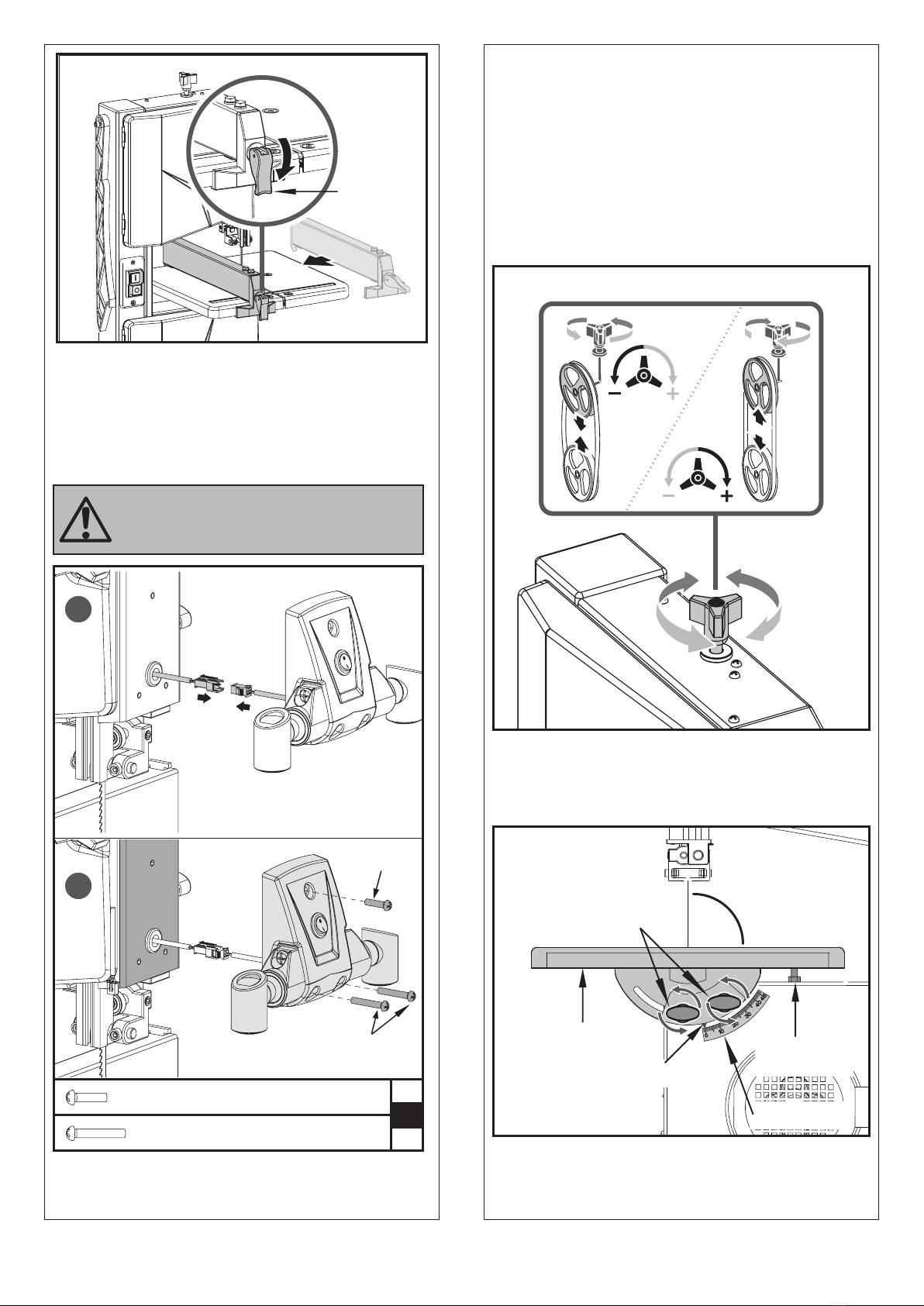
Lamp
1. Plug the cable connectors together.
2. Align the holes in the unit with the holes in the
rear plate of lamp. Secure and tighten by using
one M4x16 and two M4x25 screws.
11. Set Up
Adjusting the Blade Tension
This tracking adjustment is required to have the
blade run dead center on the rubber tyres of the
band saw wheels:
● Turning the setting knob clockwise increases
the blade tension.
● Turning the setting knob counter- clockwise
reduces the blade tension.
Adjusting the Work Table Tilting
After loosening both locking screws, the work
table tilts steplessly through 45° to the blade.
Locker
1
2
M4 ×25 (×2)
M4 ×16 (×1)
M4 ×16 ×1
B
M4 ×25 ×2
During installation do not get the
cables crushed by the screws.
Working Table
Angle Scale
Limit Stop
Screw
Pointer
Locking Screw Min: 0°

2. Loosen locking screws.
3. Using a try square, set the table at right angles to
the blade and tighten the locking screws again.
4. Loosen locking nut and adjust limit stop
screw until it touches the working table.
5. Tighten locking nut.
Setting Up the Rip Fence
The rip fence is clamped to the front. It can be
used on both sides of the blade.
Work Table Alignment
Saw Table Lateral Alignment
1. Loosen the three fastening screws that hold the
lower table trunnion.
2. Align working table so that the blade runs through
the centre of the table insert’s slot.
3. Tighten the three fastening screws again.
Aligning the work table at right angles to the
blade
1. Raise upper blade guide fully. Check band
saw blade tension.
Max: 45°
Try Square
Work Table
Limit Stop Screw
Locking Nut
9
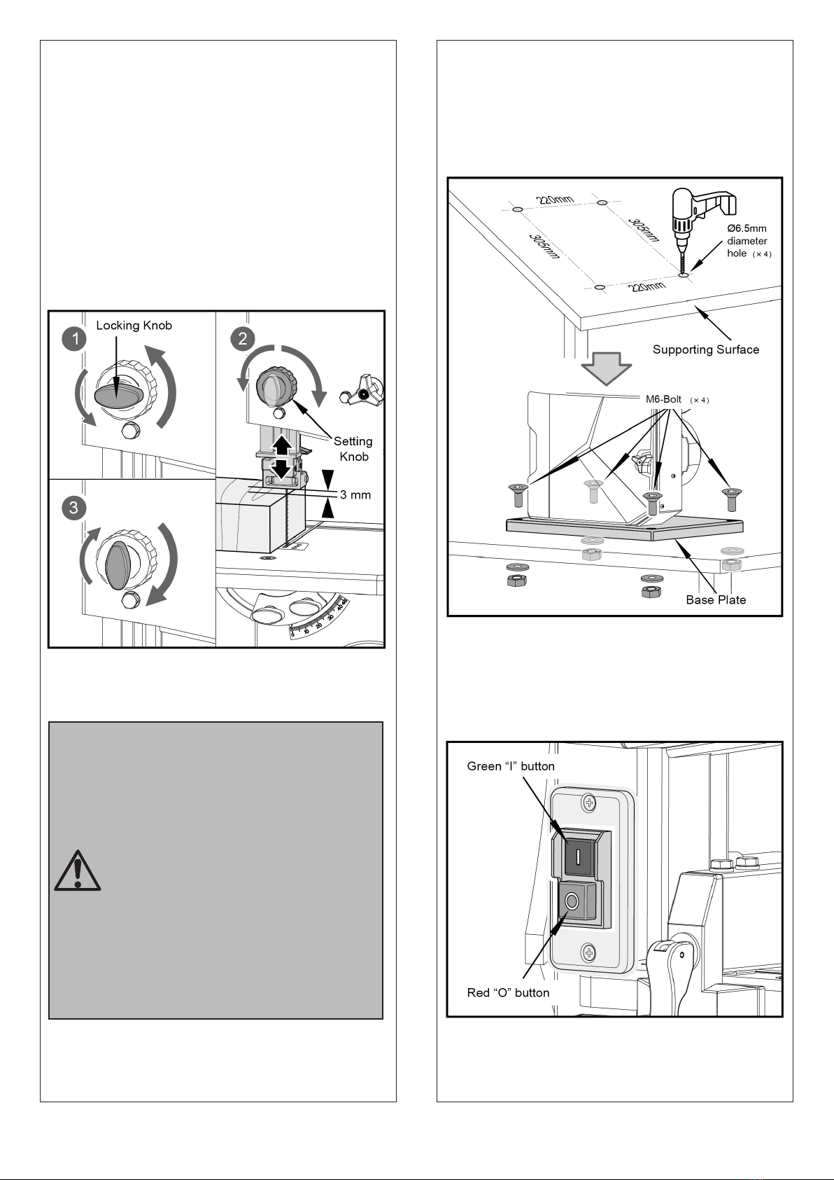
Adjusting the Blade Guard
The blade guard protects against unintentional
contact with the saw blade and from chips flying
about. In order for the upper blade guard to
provide adequate protection against contact with
the band saw blade, it must always be set as close
as possible against the workpiece
(max. distance 3 mm).
1. Loosen the locking knob.
2. Rotate the setting knob to adjust the blade
guard in the right position, then fasten the locking
knob.
12. Operation
Mounting the saw in the stable and flat
supporting surface
1. Drill 4 holes in the supporting surface.
2. Put fixing bolts through the base plate and
secure with nuts.
ON/OFF Switch
The saw can be switched on by pressing the
green pushbutton.
The red pushbutton has to be pressed to switch
off the machine.
10
Start the saw only after the following
preparations are completed:
● The saw is fastened;
● The saw table is installed and
aligned;
● Safety devices have been checked.
Connect the saw to the mains supply
only after all of the above preparations
are completed! Otherwise there is a
risk of an unintentional starting of the
saw, which can cause severe personal
injury.
11
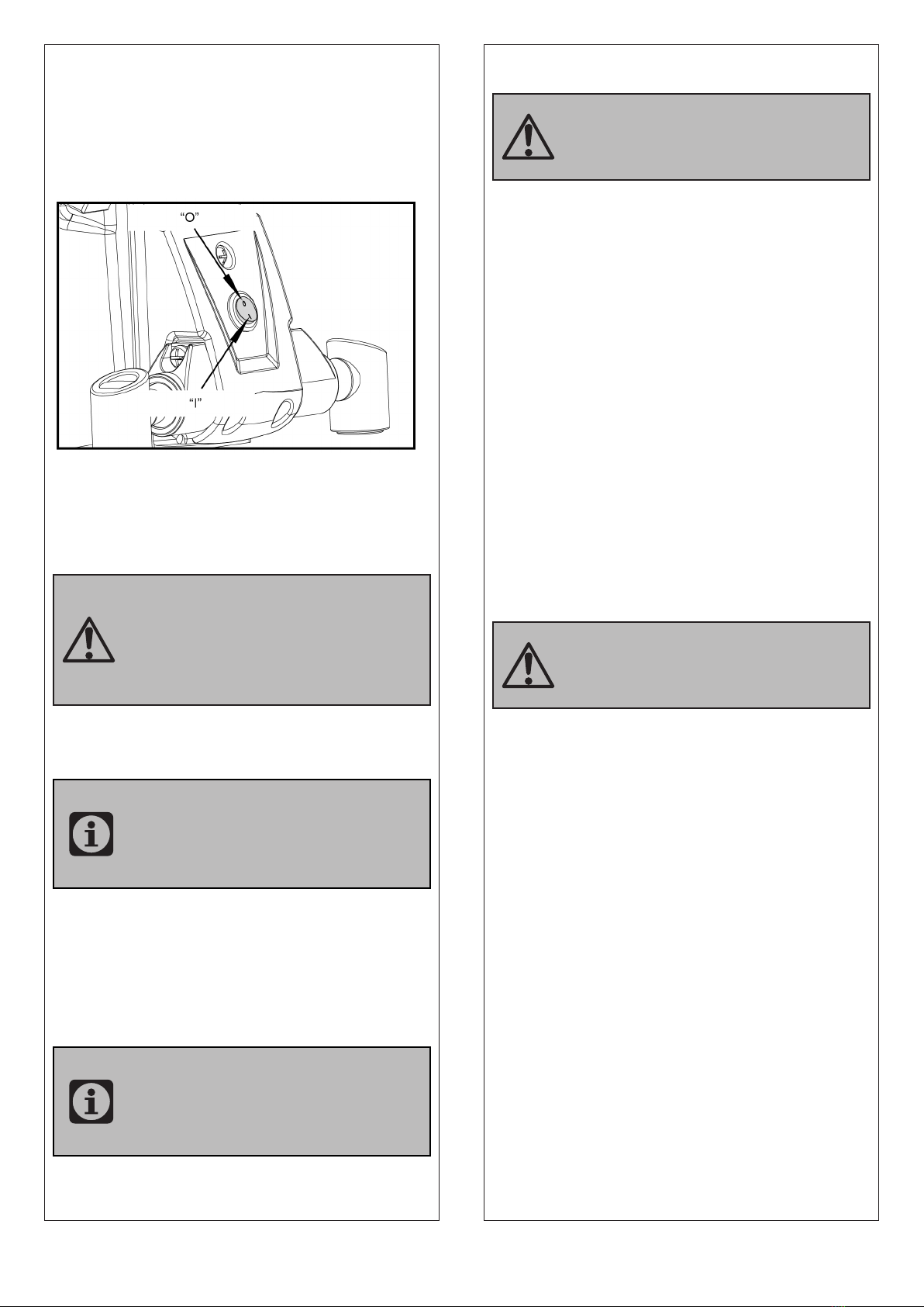
ON/OFF Switch for Lamp
Press "I" to turn on the lamp.
Press "O" to turn off the lamp
This light switch can only work when the ON/OFF
switch for the product is turned on.
Sawing
1. If necessary, adjust the table tilt.
2. Select rip fence and table tilt for the type of
cutting operation to be carried out.
3. Set upper blade guide 3 mm above the
workpiece.
4. Place workpiece on the working table.
5. Plug in.
6. Start saw.
7. Cut workpiece in a single pass.
8. Switch off if no further cutting is to be done
immediately afterwards.
13. Maintenance
General Maintenance Measures
Keep all safety devices, air vents and the motor
housing free of dirt and dust as far as possible. Wipe
the equipment with a clean cloth or blow it with
compressed air at low pressure.
We recommend that you clean the device
immediately each time you have finished using it.
Clean the equipment regularly with a damp cloth
and some soft soap. Do not use cleaning agents or
solvents; these could attack the plastic parts of the
equipment. Ensure that no water can seep into the
device. The ingress of water into an electric tool
increases the risk of an electric shock.
In order to extend the service life of the tool, oil the
rotary parts once monthly. Do not oil the motor.
Saw Blade Change
Use only suitable band saw blades.
1. Loosen the 2 knurled screws and remove the U
shape blocker.
2. Open both housing doors.
3. Loosen setting knob until the band saw blade
has slackened.
4. To remove the band saw blade, guide it through
the slot in the working table.
5. Fit fresh band saw blade. Ensure correct
position: the teeth must point towards the front
of the saw (where the doors are).
6. Center band saw blade on the rubber tyres of
the band saw wheels.
7. Tighten setting knob until blade does no longer
slip off the band saw wheels.
8. Close both housing doors.
9. Tension band saw blade;
Align band saw blade and align blade guides;
let saw test run for at least one minute;
Stop saw, unplug and recheck settings.
Always make a trial cut in a piece
of scrap to verify settings; correct
if necessary before cutting the
workpiece.
Machine has suction connector,
user can connect the machine to a
proper suction unit when working.
Danger by jamming workpiece!
When using the rip fence with a
tilted saw table, the rip fence must
be installed on the lower side of the
working table.
Warning! Prior to any adjustment,
maintenance or service work
disconnect the mains power plug!
Danger! Risk of injury, even with the
band saw blade at standstill. Wear
gloves when changing blades.

12

13
Adjusting the Blade Tension
This tracking adjustment is required to have the
blade run dead center on the rubber tyres of the
band saw wheels:
● Turning the setting knob clockwise increases
the blade tension.
● Turning the setting knob counter - clockwise
reduces the blade tension.
Band Saw Blade Alignment
If the band saw blade does not run in the centre
of the rubber tyres, the tracking needs to be
corrected by adjusting the tilt of the upper band
saw wheel:
1. Loosen locking nut.
2. Turn setting knob:
● Turn setting knob clockwise if the band saw
blade runs towards the front of the saw.
● Turn setting knob counter- clockwise if the
band saw blade runs towards the rear of the saw.
3. Tighten locking nut.
Upper Blade Guide Alignment
The upper blade guide consists of:
● a thrust bearing (supports the band saw blade
from the rear),
● two guide pins (providing lateral support).
The bearing and guide pins need to be readjusted
after every band saw blade change or tracking.
Thrust bearing adjustment
1. If necessary, align and tighten the band saw
blade.
2. Loosen the thrust bearing’s locking screw.
3. Adjust thrust bearing position (distance thrust
bearing - band saw blade = 0.5 mm
- if the band saw blade is turned by hand, it shall
not touch the thrust bearing.
NOTE: Periodically check all bearings
for wear, if necessary replace both
guide bearings at the same time.
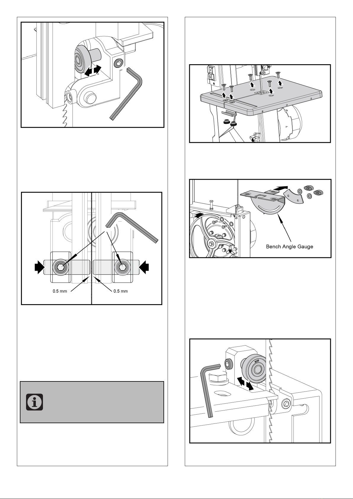
14
Thrust bearing adjustment
1. Loosen the two screws and remove the under
blocks.
2. Loosen the three screws and Remove the
working table from the table trunnion .
3. Loosen the two knobs and remove the bench
angle gauge.
4. Open the lower housing door.
5. Raise upper blade guide fully.
6. If necessary, align and tighten the band saw
blade.
7. Loosen the thrust bearing's locking screw.
8. Adjust thrust bearing position (distance thrust
bearing - band saw blade = 0.5 mm
- if the band saw blade is turned by hand, it shall
not touch the thrust bearing.
4. Tighten the thrust bearing locking screw.
Guide pin adjustment
1. Loosen screws.
2. Press guide pins together, keep 0.5 mm
distance between guide pin and the saw blade.
3. Tighten screws again
Lower Blade Guide Alignment
The lower blade guide consists of:
● a thrust bearing (supports the band saw blade
from the rear),
● two guide pins (providing lateral support).
NOTE: Periodically check thrust
bearings and guide pins for wear, if
necessary replace both guide pins
at the same time.

15
Store the device and its accessories in a dark, dry and
frost-proof place that is inaccessible to children. The
optimum storage temperature is between 5 and 30˚C.
Store the electrical tool in its original packaging.
Cover the electrical tool in order to protect it from
dust and moisture.
Store the operating manual with the electrical tool.
Danger! Store the Band saw a way it
cannot be started by unauthorised
persons and that nobody can be injured.
Caution! Do not store the Band saw
unprotected outdoors or in a moist
environment.
14. Transport
1. Turn off the power tool before any transport
and disconnect it from the power supply.
2. Apply the power tool at least with two people,
do not touch the table extensions.
3. Protect the power tool from knocks, bumps
and strong vibrations such as during transport in
vehicles.
4. Secure the power tool against overturning and
sliding.
5. Never use the safety devices for handling or
transporting purpose.
15. Storage
9. Tighten the thrust bearing locking screw.
Guide pin adjustment
1. Loosen screws.
2. Press guide pins together, keep 0.5 mm
distance between guide pin and the saw blade.
3. Tighten screws again.
4. Attach the working table to the table
trunnion.
5. Fit the U shape under block to the working
table.
Table Insert Replacement
The table insert needs replacement when its slot
has become enlarged or damaged.
1. Remove table insert from saw table (push up
from underneath).
2. Fit new table insert.

16
Trouble Shooting
Problem Cause Remedy
Motor does not
work
1. Motor, cable or plug defective,
fuses burnt
2. Housing cover open (limit switch)
1. Arrange for inspection of the
machine by a specialist. Never repair
the motor yourself. Danger! Check
fuses and replace as necessary
2. Close housing cover exactly
The motor starts
up slowly and does
not reach operating
speed
Voltage too low, coils damaged,
capacitor burnt
Contact the utility provider to check
the voltage
Arrange for inspection of the motor by
a specialist
Arrange for replacement of the
capacitor by a specialist
Motor makes
excessive noise Coils damaged, motor defective Arrange for inspection of the motor by
a specialist
The motor does not
reach its full power
Circuits in the network are
overloaded (lamps, other motors,
etc.)
Do not use any other equipment or
motors on the same circuit
Motor overheats
easily
Overloading of the motor,
insufficient coolinof the motor
Avoid overloading the motor while
cutting, remove dust from the motor in
order to ensure optimal cooling of the
motor
Saw cut is rough
orwavy
Saw blade dull, tooth shape
not appropriate forthe material
thickness
Resharpen saw blade and/or use
suitable saw blade
Workpiece pulls
awayand/or
splinters
Excessive cutting pressure and/
or saw bladenot suitable for use Insert suitable saw blade
Saw blade is not
running straight
1. Guide has been wrongly set
2. Wrong saw blade
1. Set the saw blade guide according
to the operating instructions
2. Select a saw blade according to the
operating instructions
Burn marks appear
on the wood during
the cutting work
1. Blunt saw blade
2. Wrong saw blade
1. Change the saw blade
2. Select a saw blade according to the
operating instructions
Saw blade jams
during cutting work
1. Blunt saw blade
2. Deposits on the saw blade
3. Guide has been set poorly
1. Change the saw blade
2. Clean the saw blade
3. Set the saw blade guide according
to the operating instructions

17

18
No. Description No. Description
1Lower Housing Door 39 Big Flat Washer 6
2Door Locker M6×26 40 Key 5×14
3Lock Nut M6 41 Band Saw Wheel-Lower
4Screw M5×25 42 Column Plug
5Nut M5 43 Setting Knob for Blade Tension
6Flat Washer 4 44 Thin Nut M8
7Screw M4×8 45 Adjusting Rod
8Upper Housing Door 46 Support Bushing
9Push Stick 47 Screw M4×25
10 Screw M6×35 48 Microswitch Box Cover
11 Nut M6 49 Microswitch
12 Blade 50 Microswitch Box
13 Circlip for Shaft 10 51 Nut M4
14 Bearing 6000-2Z 52 Power Cord Buckle
15 Circlip for Hole 53 Cable Clip
16 Band Saw Wheel-Upper 54 Hood
17 Rubber Tyre 55 Bolt M6×16
18 Upper Pulley Shaft 56 Flat Washer 6
19 Circlip for Shaft 8 57 Big Flat Washer 8
20 Horizontal Shaft 58 Nut M8
21 Upper Wheel Shaft Seat 59 Setting Knob for Blade
Tracking Adjustment
22 Thin Nut M10 60 Setting Knob for Blade Guard
23 U-Shaped Bracket 61 Pressing Spring
24 Central Spindle 62 Wing Cap
25 Wing Spring 63 Locking Knob
26 Guide Plate Assembly 64 Bolt M6×16
27 Nut M6 65 Bench Angle Gauge
28 ON/OFF Switch 66 Lock Plate
29 Screw M4×12 67 Lower Blade Guard
30 Switch Plate 68 Plug & Power Cord
31 Cable Sheath 69 Motor
32 Cable Fixing Plate 70 Bolt M8×65
33 Cable Pressing Plate 71 Brush
34 Screw M4×10 72 Bushing
35 Spring Washer 4 73 Nut M8
36 Lock Washer 4 74 Bolt M5×10
37 Bolt M6×12 75 Bolt M6×35
38 Spring Washer 6 76 Bolt M6×20

19
No. Description No. Description
77 Flat Washer 8 110 Upper Blade Guide
78 Table Insert 111 Upper Guide Pin
79 Work Table 112 Bearing Shaft
80 Bolt M6×20 113 Bearing 625-2Z
81 U-Shaped Blocker 114 Screw M6×12
82 Knurled Nut 115 Pin 2.5×12
83 Rip Fence Locker 116 Lower Blade Guide
84 Pin 3×16 117 Lower Guide Pin
85 Connecting Bushing 118 Upper Microswitch Cable
86 Flat Washer 10 119 Lower Microswitch Cable
87 Rip Fence Holder 120 End Wire Connector
88 Stop Block 121 Cable Gland Strain Relief Connector
89 Clamping Block
90 Rip Fence
91 Bolt M6×10
92 Rip Fence Spring
93 Clamping Press Plate
94 Clamping Screw Rod
95 Suction Connector
96 Lock Washer 5
97 Machine Body Weldment
98 Circlip 14
99 Sliding Plate
100 Screw ST3.5×9.5
101 Dust Cap
102 Rack
103 Upper Blade Guard
104 Bolt M6×60
105 Gear
106 Guide Block
107 Fixing Rod
108 Upper Blade Guide Seat
109 Screw M6×6
Table of contents
Other djm direct Saw manuals


Popular Saw manuals by other brands


Baileigh Industrial
Baileigh Industrial TS-1040E-1.0 30 Operator's manual

Siefken
Siefken CUTTING DAMON CD3525 instructions

Cedima
Cedima CTS-125 G Operating manual and safety instructions

Craftsman
Craftsman 315.212300 owner's manual

Makita
Makita LB1200F instruction manual

TYROLIT Hydrostress
TYROLIT Hydrostress FSG513 Operating manual / spare parts list