dk DK-1100A User manual

RR
DK-1100A Ink Roll Coder
Operation Manual
SHANGHAI DIXIAO CODING INDUSTRY CO., LTD.
SHANGHAI DIKAI SEPARATE MACHINERY CO., LTD.
Add: 6F, NO.2 Building, 32# Wudong Rd,
Haida Industry Zone, Shanghai 200433, China
Tel : 86-21-51086700
Fax: 86-21-55663921, 65103402

NOTICE
The use of this or any industrial system may involve hazards such as hot surfaces, sharp
objects, or nip points, as well as danger from exposure to electrical and/or pneumatic power,
UV or laser radiation, or hazardous chemicals. This manual is provided to assist you in the
safe and efficient use of your system. Read and follow the instructions carefully for
maximum safety, and to obtain the best use of your system and supplies.
All systems and supplies, whether considered hazardous or not, should be used in
accordance with principles of good manufacturing practice.
If you have questions or comments, please visit our website at
www.dikaiproducts.com
KNOW HOW TO USE THIS SYSTEM SAFELY
BEFORE YOU START TO USE IT

GENERAL TABLE OF CONTENTS
1. GENERAL & SAFETY INFORMATION
2. PRODUCT DESCRIPTION
3. INSTALLATION AND RELOCATION
4. TROUBLE-SHOOTING
5. ROUTINE MAINTENANCE
6. SCHEMATICS AND PARTS ILLUSTRATIONS
7. MANUAL REVISION EXPLANATION
8. DK HOT INK ROLL INTRODUCTION AND METHOD OF APPLICATION
9. MAINTENANCE CARD

DK-1100AInk Roll Coder Operation Manual
1. GENERAL & SAFETY INFORMATION
1.1 General Information
This handbook aims to introduce how to install, operate and maintain the DK-1100A High-speed Ink
Roll Coder safely.
Thanks for choosing DIKAI as your supplier. Any problems, please contact the local office or
distributor that will provide you with instant and ideal service.
Labels
Model Number/Serial Number/others
RR
Shanghai Dikai Separate
Machinery Industry Co.,Ltd.
NO. 32 Wudong Road, Shanghai, ChinaNO. 32 Wudong Road, Shanghai, China
Model: DK-1100A
AC 220V 50 / 60Hz 130 W 2A
S/N: 11110001A Year: 2011
Http://www.dikaiprodrcts.com Tel: 86-21-51086700
Mail:info@dikaiproducts.com Fax:86-21-65103908
There is a label on the back panel of the Control Box (see below for label description).
Model Number
Factory Location
Serial Number
Electricity Requirements
Producing Year
DK Logo
Contact Information
CE Label
SHANGHAI DIKAI SEPARATE MACHINERYCO., LTD.SHANGHAI DIKAI SEPARATE MACHINERYCO., LTD. 1-41-4

1-51-5
DK-1100AInk Roll Coder Operation Manual
1.2 Safety Information
Before operating this unit, read this manual thoroughly. Pay particular attention to the WARNINGS
AND CAUTIONS to prevent possible injury to personnel.
DANGER: Automatic packaging machine start-up after a printer reset! Install the printer Fault Output
Signal for manual packaging machine reset. Automatic start-up of a packaging machine could kill or
seriously maim an operator.
The printer installer is responsible for implementing the Fault Output Signal in a way that requires
the operator to manually restart the packing machine after a printer condition has been cleared. Any
deviation from this method is unsafe and is not approved by DIKAI or applicable regulatory
agencies.
The DK-1100A printer has an optional feature which enables it to stop or prevent packaging
machine operation when printer conditions prevent marking the packages. These conditions include,
but are not limit to, FAULT, WARMUP PERIOD and PRINT DISABLED STATUS. Some of these
printer conditions are cleared manually by the operator, and some are cleared automatically. In
either case, if the printer has not been properly connected, the packaging machine can begin
cycling when the condition is cleared. Failure to observe this may result in personal injury.
There are various ways for an installer to use the DIKAI printer Fault Output Signal to control a
packaging machine. Only someone familiar with the packaging machine can determine the best way
to signal it with an external device like the DIKAI printer. If doubt, consult the manufacturer of the
packaging machine.
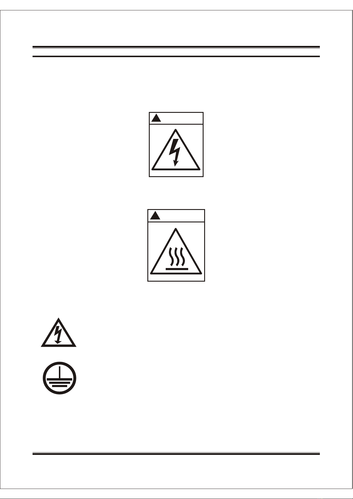
WARNING: line voltages. Remove the power line cord AND the fault cable from the control box
before repairing the DK-1100A printer. Failure to do so can result in serious injury from an electrical
shock.
NOTICE: Failure to install the ground wire may result in random machine shutdown. Make sure to
install the ground wire to the control box.
IMPORTANT: Never connect or disconnect the cables to the DK-1100 A control box with the power
on. Damage to the electronics may occur.
IMPORTANT: DO NOT operate the DK-1100A during the warm up period. It takes 15-20mins to
reach operating temperature.
IMPORTANT: DO NOT touch the Print Head during the heating status, it may result in injury.
IMPORTANT: DO NOT run the printer when any covers are taken off.
SHANGHAI DIKAI SEPARATE MACHINERYCO., LTD.SHANGHAI DIKAI SEPARATE MACHINERYCO., LTD.

DK-1100AInk Roll Coder Operation Manual
Safety Labels
This label is located on the back panel of Control Box. This label warns the operator that the printer
should be well ground connected.
This label is located on the print head front cover.
This label warns the operator to repair the printer after disconnecting the power.
This label warns the ground connection.
!
WARNING
!
WARNING
SHANGHAI DIKAI SEPARATE MACHINERYCO., LTD.SHANGHAI DIKAI SEPARATE MACHINERYCO., LTD. 1-61-6

DK-1100AInk Roll Coder Operation Manual
2. PRODUCT DESCRIPTION
DK-1100A is an electronic continuous motion coder designed to print an area as described in the
DK-1100A Machine Specifications. The DK-1100A will product imprint on all common packaging
materials at rates up to 300 prints per minute and at film speed up to 35meters per minute with
below features:
Stable Printing
Less Mechanism Consume
Compact Size
Simple Installation
SHANGHAI DIKAI SEPARATE MACHINERYCO., LTD.SHANGHAI DIKAI SEPARATE MACHINERYCO., LTD.2-72-7

DK-1100AInk Roll Coder Operation Manual
2.1 Working System
Hot Ink Roll
Rubber Wheel
Hot Ink Roll
Rubber Wheel
Pressure RollerPressure Roller
RollerRoller
Packaging FilmPackaging Film
Diagram 1
1. The Types contact the Hot Ink Roll and get the ink;
2. The Types are driven by the Rubber Wheel and Pressure Roller to continue moving, then touch the
packing film to produce imprint.
3. The Rubber Wheel and Rubber Roller must keep in good contact to ensure the clarity and
consistency of the printing.
SHANGHAI DIKAI SEPARATE MACHINERYCO., LTD.SHANGHAI DIKAI SEPARATE MACHINERYCO., LTD. 2-82-8

DK-1100AInk Roll Coder Operation Manual
2.2 Dimensional Drawing of Bracket
Diagram 2
PrinterPrinter
RollerRoller
Pressure RollerPressure Roller
SHANGHAI DIKAI SEPARATE MACHINERYCO., LTD.SHANGHAI DIKAI SEPARATE MACHINERYCO., LTD.2-92-9

DK-1100AInk Roll Coder Operation Manual
2.3 Dimensional Drawing of Print Head
Diagram 3
The Print Head can be top-installed and side-installed.
SHANGHAI DIKAI SEPARATE MACHINERYCO., LTD.SHANGHAI DIKAI SEPARATE MACHINERYCO., LTD. 2-102-10

DK-1100AInk Roll Coder Operation Manual
2.4 Machine Specifications
Print Area Axial = 40mm
Radial = 45.5mm
Printing Lines T-type (axial) up to 13lines, max. 20 characters per line
R-type (radial) up to 10lines, max. 13characters per line
Font Size T-type 1.5 mm 2.0 mm 2.5 mm, 3.0mm * 3.5mm
R-type 3.5mm*3.5, 4.5, 5.5mm
special letters and font can be custom-made
Cycle Rate up to 300 prints/ minute
Surface Speed up to 35 meters/ minute
Pouch Length 38mm 4-up printer
75mm 2-up printer
Type of Print Head Right-hand (Clockwise
Left-hand (Counter-clockwise)
Control Box LED display
Ink Roll Required Ö36*40 mm
Electrical AC100-AC230V 50/60 Hz
Power 130W 2A Fuse
Environmental Operating Temperature 4 -40
Relative Humidity 10%-95%
Weight Print Head 2.0kg Control Box 1.0kg
Dimensions Print Head 120mm*100mm*170mm (L*W*H)
Control Box 180mm*180mm*102mm (L*W*H)
SHANGHAI DIKAI SEPARATE MACHINERYCO., LTD.SHANGHAI DIKAI SEPARATE MACHINERYCO., LTD.2-112-11

DK-1100AInk Roll Coder Operation Manual
3. INSTALLATION AND RELOCATION
3.1 Installation
3.1.1 Installation Requirements
3.1.2 Checking Home Position of the Type Holder
Packaging machine runs well
Stable power supply AC220V 10V, max. 2A fuse
Reliable printing signal can be from relay, proximity sensor or PLC
Enough space for installing printer
At the very beginning of the installation, manually check the home position, that is the Hot Ink Roll,
Rubber Roller and Pressure Roller should be in position as diagram 4. The rubber wheel can not
touch pressure roller or packing film. Otherwise, it will cause failed or missed printing.
Diagram 4
Hot Ink Roll
Rubber Wheel
Hot Ink Roll
Rubber Wheel
Pressure RollerPressure Roller
RollerRoller
Packaging FilmPackaging Film
SHANGHAI DIKAI SEPARATE MACHINERYCO., LTD.SHANGHAI DIKAI SEPARATE MACHINERYCO., LTD. 3-123-12

DK-1100AInk Roll Coder Operation Manual
3.1.3 Installing and Mounting the DK-1100A Print Head
Install the mounting bracket assembly to the packing machine where
will be easy to operate the printer. Make sure there will be room in
front of the print head for the operator to change the ink roll and type
holder. The packaging film can round through the pressure roller and
make less than 120 wrap (as diagram 5).
3.1.4 Installing the Control Box
PrinterPrinter
Packaging FilmPackaging Film
RollerRoller
120120
Diagram 5
IMPORTANT: Mount the control box away from potential sources of water spray or cleaning
solutions. The control box connectors are not sealed from harsh
environments.
Install the print head cable to the print head, as below diagram.
I/O cable This cable has 3-pin plug-in, can input print signal. Match the proximity sensor to
the correct color wires. Refer to Diagram 6.
Drive cable: This cable has 7-pin plug-in, connecting the print head and the control box.
Power cable: This cable has plug-in and three wires, connecting the control box and power
supply. The cable can get the power supply from packaging machine.
IMPORTANT: Never connect or disconnect the cables to the DK-1100A control box with the
power on. Failure to do this may result in personal injury.
NOTE Requires AC220V 50/60Hz power, well ground connection.
I/O
Cable
Data
Cable
1
0
I/O Drive Connect
Power Supply
AC 220V
Power Cable
Diagram 6
SHANGHAI DIKAI SEPARATE MACHINERYCO., LTD.SHANGHAI DIKAI SEPARATE MACHINERYCO., LTD.3-133-13

DK-1100AInk Roll Coder Operation Manual
3.1.5 Print Signals
Use an inductive proximity switch to sense a rotating or moving metal
device such as a vane, bolt head, or cam lobe.
1. Connect the proximity switch with the I/O cable.
2. Mount the proximity switch in front of a lug or vane (around 15mm
wide) that will make one actuation for each product.
3. Position the mounting nuts on the proximity sensor so that the
switch end is not further 2mm from the vane or lug.
Use a photo sensor to sense the marking in the packing film.
Use a contact closure as the print go sensor. Connect the blue wire to
one terminal and black wire to the other terminal of a normally open
voltage free contact.
Photo Sensor
PLC
Proximity Sensor
IMPORTANT: Keep the correct switch position (as Diagram 7) before installing the sensors or
getting print signal from PLC of packaging machine.
Diagram 7
SIGNAL POSITION
NPN Sensor
PNP Sensor
PLC Electrical Signal
12345
ON
OFF
OFF
OFF
OFF
ON
ON
OFF
OFF
OFF
ON
ON
ON
ON
OFF
Signal Type Configuration
Signal Type
NPN
NPN Sensor
PNP
PNP Sensor
(PLC)
Ext. Signal
Switch
Position
1. NPN
Note: When using relay signal, switch positionrefer NPN mode;
2. PLC +12V
When using the electricai (PLC) or relay signal, do not
connect the +12v (Color: BR) output wire
Details could refer to manual
54321
DP ON
54321
DP ON
54321
DP ON
Refer to Table 1.
SHANGHAI DIKAI SEPARATE MACHINERYCO., LTD.SHANGHAI DIKAI SEPARATE MACHINERYCO., LTD. 3-143-14

DK-1100AInk Roll Coder Operation Manual
3.1.6 Control Box Inter-configuration Diagram
JP1JP1 JP2JP2 JP3JP3
W1W1 W2W2 W3W3
RedRed YellowYellow
YellowYellow
Red & GreenRed & Green
RedRed Red BrownRed Brown
BlueBlue
BlackBlack
WhiteWhite
Brown Black BlueBrown Black Blue
J1J1 J6J6 J3J3 J8J8 J7J7 J11J11
DK1100ADK1100A SW1
J5J5 J4J4
W4W4 J5J5
LED BoardLED Board
ITEM NO.
DK1100A
LED BOARD
J1
J3
J4
J5
J5
J6
J7
J8
J11
W1
W2
W3
W4
JP1
JP2
JP3
SW1
Description
Main Control PCB
LED Display & Keypad
3pins, input plug-in for AC100~220V supply
2-pin output plug-in for 24V DC magnetic iron
Wire jumper shorted Auto-track Disconnection Fixed delay
16pins, output plug-in for LED Display & Keypad
16pins, input plug-in for LED Display & Keypad
2pins, AC power wire for heating tube
Unplugged
3pins, input plug-in for print signal
3pins, input plug-in for thermocouple
3pins, input plug-in for AC power wire
7-pin drive cable
3-pin signal input cable
16pin display data cable
3-pin AC power plug
7-pin air plug for the drive of head
3pins, input plug-in for external signal
Switch for the selection of external signals
SHANGHAI DIKAI SEPARATE MACHINERYCO., LTD.SHANGHAI DIKAI SEPARATE MACHINERYCO., LTD.3-153-15

DK-1100AInk Roll Coder Operation Manual
3.1.7 Interfaces for External Signal, Encoder and Fault Output Signal
1
0
Interface for power:
Interface for sensor:
Interface for drive:
Mark Description Color
EARTH
LIVE
NEUTRAL
Double
Color
Red
Black
AC~220V
2
31
2
3
1
4
5
67
SENSOR
DRIVER
L
M
Wire No.Description Color
External print signal 0V
External print signal
Output power of external print
signal +12V
1
2
3
Blue
Black
Brown
1
2
3
4
5
Heating tube exchange pin 1
Heating tube exchange pin 2
Solenoid magnet pin 1
Thermocouple negative
Solenoid magnet pin 2
Red
Red
Brown
Black
Yellow
Thermocouple compensation
pole
6
7
White
Thermocouple positive Blue
SHANGHAI DIKAI SEPARATE MACHINERYCO., LTD.SHANGHAI DIKAI SEPARATE MACHINERYCO., LTD. 3-163-16

DK-1100AInk Roll Coder Operation Manual
3.2 Relocation
3.2.1 Check the Home Position of Type Holder
In the initiate position, any one of grooves around the type holder is faced to the pressure roller, no
contact (as diagram 10). After getting the print signal, the type holder contacts pressure roller reliably (as
diagram 11), to complete one print. Failure to do so can result in the failed or missed prints (it can
relocate the pressure between rubber wheel and pressure roller to get the clear prints, refer to 3.2.2).
3.2.2 Relocating the Pressure between Pressure Roller and Rubber Wheel
Ink RollInk Roll
Typr RubberTypr Rubber
Rubber RollerRubber Roller
FilmFilm
Diagram 10 Diagram 11
Ink RollInk Roll
Typr RubberTypr Rubber
Rubber RollerRubber Roller
FilmFilm
As diagram 12, the pressure and parallelism between pressure roller and rubber wheel can be
relocated by adjusting the screws and the horizontal position of adjusting wedges. This relocation makes
the correct position between pressure roller and rubber wheel, to get legible prints. When relocating, the
operator can press the test button in the control box to make type holder rotate and check whether the
pressure and position is correct.
Diagram 12
Adjusting wedge
Type HolderType Holder
Rubber RollerRubber Roller
Adjust screwAdjust screw Adjust screwAdjust screw
SHANGHAI DIKAI SEPARATE MACHINERYCO., LTD.SHANGHAI DIKAI SEPARATE MACHINERYCO., LTD.3-173-17

DK-1100AInk Roll Coder Operation Manual
3.2.3 Relocating the Pressure between the Ink Roll and Types
IMPORTANT: Poor pressure between the ink roll and types can result in un-clear or missed prints.
1- Use the 6mm Allen wrench to take out the Allen screw in the body of print head.
2- Loose the inside M5 Allen screws.
3- Take the ink roll out, rotate the ink roll shaft manually to relocate the space between ink roll shaft and
ink roll (the ink roll shaft is eccentric).
4- Put in the ink roll to check whether the pressure is correct; if not, repeat step 3 & 4 till the pressure is
correct.
5- Tight the M5 Allen screw.
6- Reset the M8 Allen screw.
3.3 Change Date Numbers
3.4 Change the Hot Ink Roll
1- Install the type on the pins of the type holder. Secure the type to the type holder pins with the
type stoppers. Two type styles are available, depending on which way the print is oriented on
the web- radial (for printing with the web), and axial (for printing across the web).
2- Align the type holder to the type holder shaft. Push the type holder into the print head and
turn until it seats into place.
Follow the following instructions step by step:
1- Press an ink roll arbor into the ink roll.
2- Slide the ink roll arbor and ink roll on the inking shaft until it seats into place.
IMPORTANT: The PREHEATER is an optional part to preheat the ink roll and reduce the stand-by time
of the production line.
SHANGHAI DIKAI SEPARATE MACHINERYCO., LTD.SHANGHAI DIKAI SEPARATE MACHINERYCO., LTD. 3-183-18

DK-1100AInk Roll Coder Operation Manual
3.5 Instruction on the Control Box
Current temperature
RR
DK-1100A
Print indicator
Signal indicator
Heat Indicator
Auto Track Indicator
Fix Delay Indicator
Set temperature Print Delay Position
TMP Setting Button Test Button Print Button
Print Position
Display Setting
TMP. Position
TMP.
Heat
Signal
Print
Test Print
Auto Track
Fix Delay
The following is the description of functionsThe following is the description of functions
Menu Items Function Description
Temperature display
Set temperature display
Print delay position display
Print indicator light
Signal indicator light
Heat Indicator light
Auto-track indicator light
Fix delay indicator light
Temperature setting button
Print position setting button
Display current actual temperature
Display the setting temperature
In fix delay mode: delayed time ; the unit is ms
In auto-track mode: delayed percentage
Print indicator light is on when coder is opened and will be off
when coder is closed
Signal light will flash upon receipt of a print signal
When the machine is heating, heat indicator light will be on
The light will be on when it is in auto-track mode
The light will be on when it is in fix delay mode
To set the operating temperature for the heater block
Set the print position
Print button
Test button
Start or stop automatic print status
In standby mode, press the button and one print is completed
SHANGHAI DIKAI SEPARATE MACHINERYCO., LTD.SHANGHAI DIKAI SEPARATE MACHINERYCO., LTD.3-193-19

DK-1100AInk Roll Coder Operation Manual
4. TROUBLE-SHOOTING
4.1 Troubleshooting Action List
SYMPTOM POSSIBLE CAUSE ACTION
Error
Temperature
display
Light Prints
Poor Prints,
Double
Images
Incorrect
Printing
Positions
No heat or
abnormal
temperature
Display 888
Poor print pressure.
Insufficient preheating.
Depleted ink roll.
Damaged or worn type.
Temperature of the ink
roll and type is too low.
Ink build-up on type face.
Print pressure.
Heater block
temperature is too high.
The type holder is
slipping.
Unstable print signals
No display in the LED
No temperature increase
Instable temperature
display +/- 4
Check the connection between control box and print
head
Adjust to higher pressure between rubber wheel and
pressure roller by relocating the adjusting wedge.
Heat the ink roll enough.
Install a new ink roll.
Install new type.
Increase the temperature setting.
Repair the temperature controller, heater, heating
cartridge, heating tube.
Clean all printing elements.
Adjust to lower print head pressure.
Decrease the temperature setting.
Repair the temperature controller, heater, heating
probe, heating tube.
Tight the tension of the belt wheel. Tight the screw in
the main shaft.
Adjust to get the stable print signals.
Check the power supply
Check the heating tube
It is normal
SHANGHAI DIKAI SEPARATE MACHINERYCO., LTD.SHANGHAI DIKAI SEPARATE MACHINERYCO., LTD. 4-204-20
Table of contents
Popular Media Converter manuals by other brands

Lake People
Lake People ADC F466-S user manual

WAREMA
WAREMA climatronic converter WMS UP Operating and installation instructions

Marklin Digital
Marklin Digital 60948 manual

Versitron
Versitron M7260PA user manual

PR electronics
PR electronics 2255 user guide

Vertiv
Vertiv eSure C48/58-1000 installation manual