DKC Via Larga 15 User manual

COOLERS FOR ELECTRICAL ENCLOSURES
OPERATION AND MAINTENANCE MANUAL
WALL MOUNT VERSION
CLIMATIZZATORI PER QUADRI ELETTRICI
MANUALE D’USO E MANUTENZIONE
VERSIONE DA PARETE
CLIMATIZADORES PARA CUADROS ELECTRICOS
MANUAL DE USO Y MANUTENCIÓN
VERSIÓN DE PARED

2
Table of contents
CAUTION ............................................................................................................................................................ 3
GENERAL SAFETY INSTRUCTIONS ...................................................................................................................... 3
OPERATING PRINCIPLE ...................................................................................................................................... 3
ACCEPTANCE AND STORAGE ............................................................................................................................. 4
HANDLING ......................................................................................................................................................... 4
INSTALLATION.................................................................................................................................................... 4
MECHANICAL MOUNTING ......................................................................................................................... 4
MOISTURE DRAIN ...................................................................................................................................... 5
ELECTRICAL CONNECTIONS ....................................................................................................................... 5
CONTROL, MONITORING AND SAFETY COMPONENTS ..................................................................................... 5
HP SAFETY PRESSURE SWITCH ................................................................................................................... 5
MECHANICAL REGULATION THERMOSTAT (EASY VERSION) ..................................................................... 6
ELECTRONIC REGULATION THERMOSTAT (BASE/ TOP VERSION) ............................................................. 6
PARAMETER SETTING .........................................................................................................................
STATUS ICONS ....................................................................................................................................
USE OF BUTTON COMBINATIONS AND THEIR FUNCTIONS ............................................................... 8
FIRST LEVEL VARIABLES ...................................................................................................................... 8
DIAGNOSTIC CODE TABLE .................................................................................................................. 9
START-UP ......................................................................................................................................................... 10
INITIAL TESTS AFTER START-UP ............................................................................................................... 10
MAINTENANCE ................................................................................................................................................ 11
PRODUCT DISPOSAL ........................................................................................................................................ 11
TROUBLE SHOOTING ....................................................................................................................................... 12
WARRANTY ...................................................................................................................................................... 13
MANUFACTURER NAME AND ADDRESS .......................................................................................................... 14

3
CAUTION
It is important to store the present manual in a clean and dry place. It refers to activities requiring
professionally qualified staff.
Do not try to alter the product or modify its characteristics. Do not use unqualified personnel for repair
activities, it may lead to failures, damages or safety risks.
A non-observance of the instructions and restrictions given in the present manual shall waive any our
responsibility for correct functioning and warranty of the product.
GENERAL SAFETY INSTRUCTIONS
The coolers must be used only for their intended purpose; only approved coolants must be applied.
Any attempt to activate the product with no coolant gas is strictly forbidden.
Never start the cooler before all external panels have been closed in order to avoid the risk of
electrocution or contact with moving parts.
In case it is necessary to evacuate the coolant from the system, do not disperse it in the environment,
but collect it by means of special exchange units.
OPERATING PRINCIPLE
The cooler is purposed to
cool electrical enclosures. It
may be externally mounted
to an enclosure wall. It allows
air cooling and dehumidifying
inside the enclosure and
avoiding failures of electrical
and electronic components
installed therein. The cooler
is provided with an
adjustable intervention
thermostat. The cooling
circuit starts to function only
after the pre-set temperature
has been reached.
The principal components
constituting the circuit are:
evaporator, condenser,
compressor and expansion
device.
The compressor compresses
the cooling fluid (R134a) at
high pressure and
temperature.
At the output of the compressor the cooling fluid in the state of overheated vapour is transferred to the
external exchange unit (condenser), where releases the heat to the external environment and condenses
completely.

4
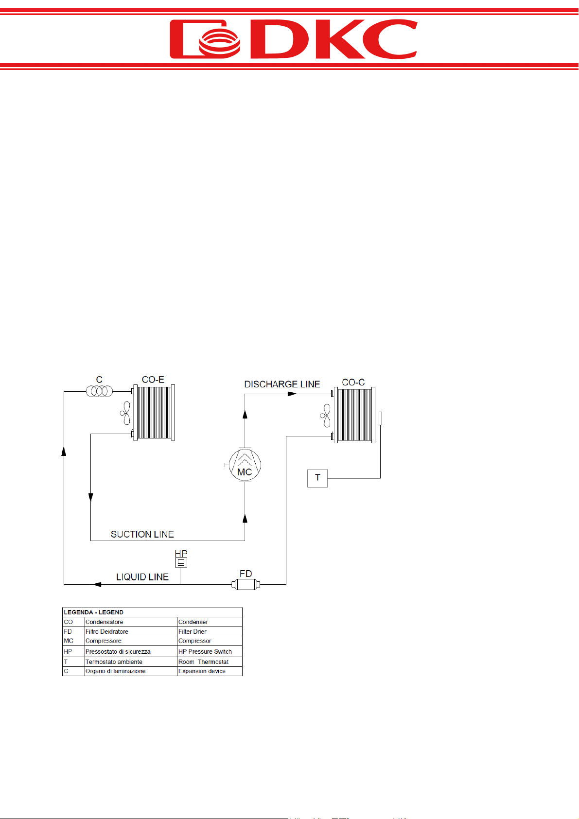
At the inlet of the evaporator the expansion device is located (capillary or thermostatic valve), purposed to
reduce the cooling fluid pressure to a value, which allows its evaporation in the cold exchanger.
The coolant passing through the evaporator changes its state taking the heat away from the source (air
inside the enclosure to be conditioned) by means of the low temperature.
The evaporator is then connected to the compressor, so the fluid in the state of overheated vapour is
drawn by the compressor to be reintroduced into the circuit.
ACCEPTANCE AND STORAGE
Upon delivery of the products it is necessary to make sure they had been transported in the position
indicated by the symbols printed onto the package.
It is necessary to ensure the packing materials are undamaged and most importantly do not show oil spots,
which denote a leakage of cooling fluid.
The cooler is designed so that the compressor remains always in upright position. It may never be laid
down; if this happens, it is necessary to put it in upright position and then wait for 8 hours before setting it
in operation.
Do not set the unit in operation if a coolant leakage is found.
Installation, maintenance and repair activities must be carried out only by qualified personnel. Only filter
substitutions may be performed by a non-specialized staff.
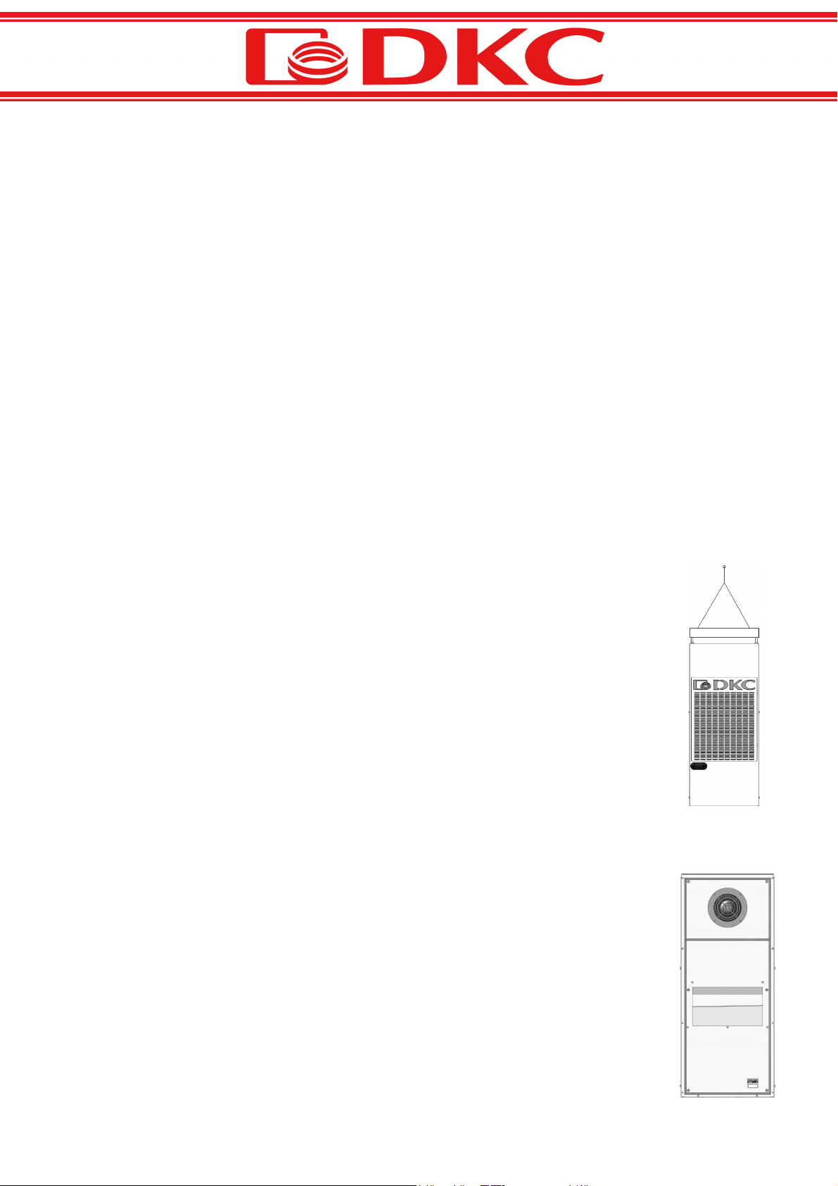
During the operations of handling and storage wall mount coolers are to be kept in vertical
position, while roof mount ones in horizontal position, at the temperature in the range
between -10°C and + 0°C.
HANDLING
Having removed the packing materials, coolers are to be handled using the dedicated fixing
points located in the upper part. Use the supplied eyebolts paying attention to balance the
cooler and to avoid any impact.
INSTALLATION
Having removed the packing materials, make sure that there are no leakages of oil or gas and
that no parts or documents are left in the package. The supply voltage indicated on the device
name plate is to be in conformity with the requested one.
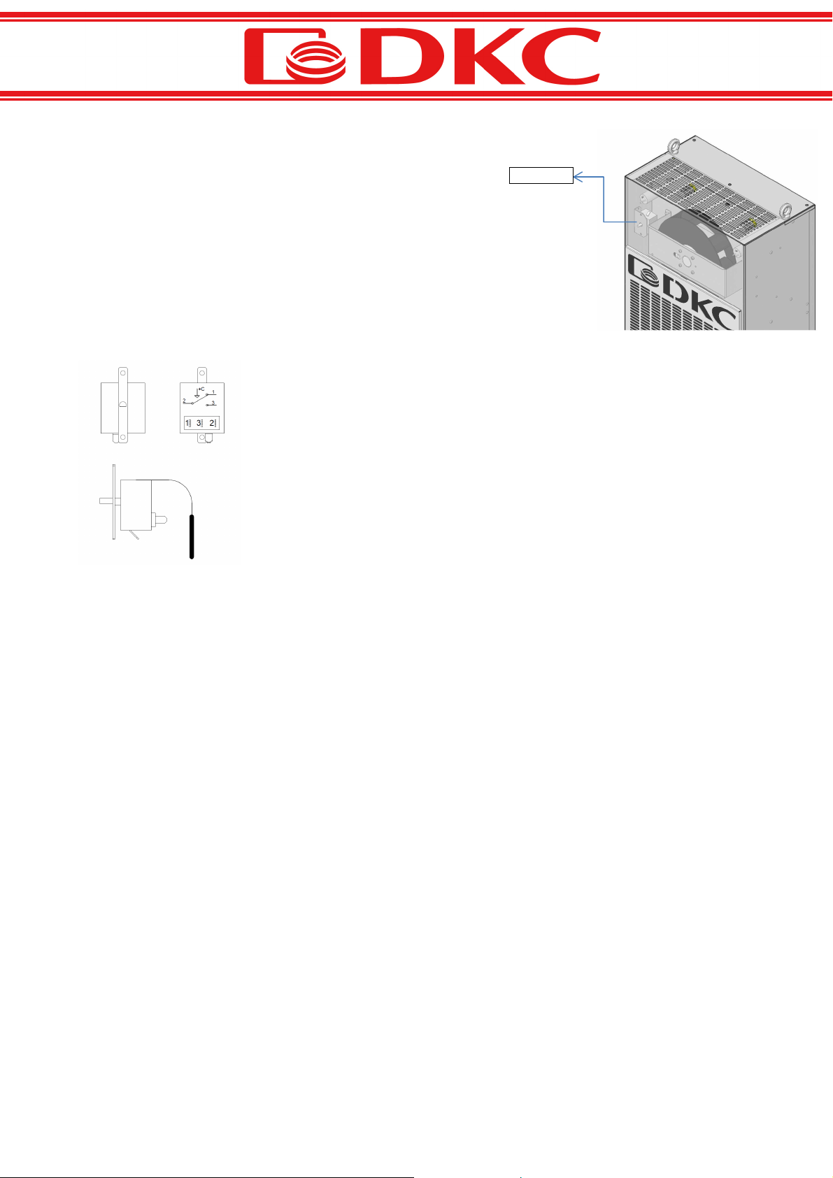
MECHANICAL MOUNTING
The coolers may be mounted inside or outside the enclosure. The cooler must always be
installed in upright position (with the compressor in the bottom) with the maximum standoff
from the upright position equal to 2°.
Before mounting it is necessary to ensure the enclosure minimum protection degree is IP54
in order avoid problems caused by external air condensing.
In case of a cooler mounting onto a door, it is necessary to verify if the hinges are capable to
sustain the device weight.
In any case the cooler is to be mounted as high as possible in order to draw out the hottest
air from the enclosure. To perform the installation it is necessary to cut the sheet steel with

5
the help of a template supplied or request its drawing at our Technical Department. The cooler is provided
with a polyurethane seal applied by continuous molding and does not require further seals reducing
significantly the installation time.
If the device is not installed correctly, the IP 54 protection degree will be lost.
MOISTURE DRAIN
BASE and TOP versions are provided with a condensate evaporator located inside the cooler. In case of
extreme environmental conditions the evaporator may be insufficient. Therefore a “too full” drain is
provided, to channel the excess liquid outside the system.
EASY version is provided with an external moisture drain.
In any case there is a joint located below the cooler base on the right side, which must be connected to a
moisture collection pipe.
ELECTRICAL CONNECTIONS
The installation is to be performed in accordance to the standards in force in the country of operation. The
supply circuit of the cooler is to be protected by a multipole magnetothermic differential switch.
Make sure the supply voltage indicated on the device name plate is in conformity with the requested one.
The cooler is provided with one or two electrical connectors located on its rear side.
A black coloured connector, which is always provided, is purposed for the cooler power connection. In case
of single-phase coolers it is necessary to connect the three clamps marked N L1 PE.
Some models (TOP version) are provided with another connector, of grey colour, purposed for signal
connection. Depending on the model they can be:
free alarm contact: the contact is closed in case the temperature inside the electrical enclosure
remains beyond a pre-set limit for a certain time;
digital input of remote ON/OFF, door opening limit switch.
In any case it is necessary to refer to the electrical circuit diagram attached to the present manual.
CONTROL, MONITORING AND SAFETY COMPONENTS
The cooler is provided with control and monitoring components assuring its correct functioning. An
intervention of these automatisms indicates a failure of the device. It is forbidden to make an electrical
bypass of the existing components. Besides being dangerous this manipulation waives the product
warrantee.
HP SAFETY PRESSURE SWITCH
The function of this component is to stop the compressor operation when the internal pressure of the
supply circuit exceeds the calibration level (24bar).

6
MECHANICAL REGULATION THERMOSTAT (EASY VERSION)
The thermostat bulb is located at the inlet of the air drawn-in from the
enclosure and monitors the temperature, sanctioning the compressor and
condenser fan activation.
Manual regulation of the thermostat is to be performed by qualified personnel,
by turning its regulation pin after having cut the power and removed the
protection housing.
Turn the pin counter-clockwise in order to increase the setpoint.
Turn the pin clockwise in order to reduce the setpoint.
Too low temperature inside the enclosure may cause serious problems to the
components and lead to excessive energy consumption.
It is recommended to set a temperature not lower than 30°C and not higher
than 40°C. It is reminded that the thermostat has a differential of
approximately 4 °C and hence the compressor shall start functioning at a
temperature exceeding the deactivation temperature approximately by 4°C.
The manufacturer default setting is 35°C.
ELECTRONIC REGULATION THERMOSTAT (BASE/ TOP VERSION)
It indicates the internal enclosure temperature while in operation.
The setpoint is pre-set by the manufacturer to the value of 34°C with a differential of 2°C.
The cooler is activated at the default temperature (34°C) and deactivated at the default temperature plus
the differential (36°C).
The thermostat is provided with a minimum time delay between the deactivation and the next activation of
the compressor equal to three minutes.
Thermostat

7
PARAMETER SETTING
BUTTON
FUNCTION
UP BUTTON
Increases values / Scrolls the parameters up
Mutes the alarm, if any
DOWN
BUTTON
Decreases values / Scrolls the parameters down.
Stand
-
by
If kept down for more than 1 sec,
alternates the Stand
-
by state to the normal
functioning state and vice versa. A BEEP is produced to confirm the state
alteration. In Stand-by the system is not functioning and OFF sign alternates the
temperature value on the display.
Set
Displays the
setpoint
Allows to set the setpoint if pressed simultaneously with UP or DOWN button.
STATUS ICONS
ICON
MEANING
REFRIG
E
RATION CO AND ICON
LED OFF = Refrigeration OFF
LED ON = Refrigeration ON
Flashing LED = Refrigeration ON holding up the delay time (3 minutes after the previous stop)
ALAR
ICON
LED OFF = No alarm
LED ON = Indicates, that a temperature alarm has been given and then withdrawn (HACCP alarm).
Flashing LED = Active alarm

8
USE OF BUTTON COMBINATIONS AND THEIR FUNCTIONS
FUNCTION / BUTTON COMBINATION
SET CONFIGURATION
/
/ /
/
(Set +
(Set + (Set +
(Set + t
tt
to
oo
ou
uu
u)
))
)
Press the "Set" button to view the current SETPOINT value (temperature).
Keeping the "Set" button down and pressing one of the two buttons (t) or (u) the SETPOINT value is modified.
To return to the temperature viewing the "Set" is to be released, modified settings shall be automatically saved.
1st LEVEL PROGRA ING
/
/ /
/
(
((
(t
tt
t+
++
+u
uu
u)
))
)
Press and hold simultaneously “UP” and “DOWN” buttons for more than 3 sec in order to access the first level
programming menu. Having accessed the menu a confirmation BEEP is generated. After 30 sec the menu is exited
automatically.
FIRST LEVEL VARIABLES
VARIABLE
EANING
DEF.
r0
Temperature differential
referred
to the main
SET
POINT
< Range: 0,2 ÷ 10°C >
It is expressed by an absolute value and defines the hysteresis of the temperature to the
SETPOINT.
2
A1
inimum temperature alarm
< Range: - 45 ÷ -20 °C >
The absolute temperature referred to the environment probe, below which the LOW
temperature alarm is activated upon the delay time (6 minutes) expiration, consisting in an
alternation of EL symbol and the temperature on the display and the alarm icon flashing.
After the alarm has ended, the alarm icon remains on, in order to signal its intervention,
until the UP button is pressed.
0
A2
aximum temperature alarm
< Range: 3 ÷ 10 °C >
If the temperature exceeds the value equal to (setpoint+r0+A2), upon the delay time (6
minutes) expiration, the HIGH temperature alarm is activated, consisting in an alternation
of EH symbol with the temperature on the display and the alarm icon flashing.
After the alarm has ended, the alarm icon remains on, in order to signal the alarm
intervention, until the UP button is pressed.
10

9
DIAGNOSTIC CODE TABLE
Var
EANING
E0
X
Environmental probe functional failure
E2
X
EEPROM
memory error
.
All outputs are deactivated, except the alarm ones, if
any.
EH
X
Maximum temperature alarm
.
Flashing EH symbol alternated with the temperature
(See A2 parameter)
EL
X
Minimum temperature alarm.
Flashing EL symbol alternated with the temperature
(See A1 parameter)
orH
Temperature out of the upper range
(> +99.0°C)
orL
Temperature out of the lower range
(<
-
45.0°C)

10
START-UP
Having performed the installation, it is recommended to wait for at least 30 minutes before starting the
system up, in order to allow the lubricant oil collection in the compressor.
Normally upon the system start-up only the evaporator fan is activated, purposed for the air recycling
inside the enclosure. The compressor and the external air fan are not activated, if the internal enclosure
temperature is lower than the one set on the thermostat. In order to test the system, it is necessary to
increase the enclosure internal temperature or decrease the set temperature (35°C set as a default by the
manufacturer).
At these conditions the compressor and the condenser fan are activated. The internal circulation fan must
be always functioning, while the external fan is activated and deactivated simultaneously with the
compressor.
Having tested the correct functioning of the system, it is necessary to set the internal temperature
thermostat to the required value (recommended value 35°C)
INITIAL TESTS AFTER START-UP
Make sure that the air coming from the condenser fan is not drawn back into the enclosure. Observe the
minimum distances specified at the figure below.

11
MAINTENANCE
Maintenance activities must be performed by qualified personnel.
The refrigerant system of the cooler is hermetically closed and does not require any scheduled ordinary
maintenance. It is necessary to perform service operations only in case of a problem.
If the system is provided with a filter, it is recommended to replace or clean it every month.
It is recommended to check the moisture drain approximately every two months to make sure that it is
unobstructed and well-functioning.
Every six months it is necessary to ensure the condenser is clean. If it is not, perform the following
operations:
Deactivate the power supply.
Unscrew the external housing and remove it.
Clean the condenser fins with compressed air or, if necessary, with a solvent.
Mount the housing making sure to have the earthing wire connected.
PRODUCT DISPOSAL
This device must be dismantled by authorized bodies. The coolant liquid and oil contained in the refrigerant
circuit must be recovered and recycled in accordance with the regulations.

12
TROUBLE SHOOTING
TROUBLE
CAUSE
ACTION
T
he cooler
fail
s
to start
The cooler is not powered
Check the
power supply
switches/fusibles and the
electrical connections of the
system
Th
e cooler star
ed,
but
fails to
refrigerate
The cooler is not charged
Search for a coolant leakage,
repair it and charge the cooler
(qualified personnel only)
The thermostat failed
Replace the thermostat
The compressor failed
Replace the compressor
(qualified personnel only)
HP pressure switch failed
Replace the HP pressure switch
(qualified personnel only)
The compressor works
intermittently even if the
enclosure temperature is above
the set value of the thermostat
Thermal s
hort
-
circuit of the
condenser air.
Check the minimum distance
from walls or other coolers.
Remove the obstacles, if any.
The room temperature
exceeds
the maximum allowable one
Air the room
.
Modify the position of the cooler.
The air filter or the condenser is
unclean
Clean or r
eplace the air filter
.
Clean the condenser coil.

13
WARRANTY
DKC Europe Srl guarantees that the product is free of quality defects.
The warranty period is 12 months from the shipping date (stated in the bill of lading) and terminates upon
the expiration of this period, even if the Products for whatever reason have never been set in operation.
In case of a Product installation and/or setting in operation subsequently to the shipping date (stated in the
bill of lading), it is possible (filling in the attached module for “DKC EFFECTIVE WARRANTY – RAM KLIMA”
on a mandatory basis) to get the warranty effective date started at the date stated in the module dully
filled in and signed by the Customer and addressed to DKC Europe Srl.
In this case it is understood that the overall Warranty Period shall never exceed 18 months from the first
shipping date.
The warranty is valid for all the product components only and exclusively if the instructions of this manual
and the operating limits stated on the nameplate are strictly observed.
The warranty is waived in case of damages caused by incorrect storage.
The product shall be repaired by our personnel at the Customer’s site or at our charge. If the repair
activities have to be performed at our workshop, the products shall be delivered at the Customer’s or End
User’s charge.
At no circumstances claims for damage or loss reimbursement shall be made in connection with costs,
standby time and other consequences caused by the product failure.
The warranty is waived in case the Customer is not regular with the payment.
The warranties required by law remain valid.

14
MANUFACTURER NAME AND ADDRESS
DKC EUROPE SRL
15, Larga str.
20122 ilan, ITALY
Manu acturing Plant in Rome
60, Ranuncoli str.
00134 S. Palomba (Rome), ITALY

15
AVVERTENZE .................................................................................................................................................... 16
ISTRUZIONI GENERALI DI SICUREZZA .............................................................................................................. 16
PRINCIPIO DI FUNZIONAMENTO ..................................................................................................................... 16
RICEVIMENTO E STOCCAGGIO ......................................................................................................................... 1
MOVIMENTAZIONE ......................................................................................................................................... 1
INSTALLAZIONE ................................................................................................................................................ 1
MONTAGGIO MECCANICO ....................................................................................................................... 1
SCARICO DELLA CONDENSA ..................................................................................................................... 18
COLLEGAMENTI ELETTRICI ....................................................................................................................... 18
COMPONENTI DI COMANDO CONTROLLO E SICUREZZA ................................................................................ 18
PRESSOSTATO DI SICUREZZA ALTA PRESSIONE ....................................................................................... 18
TERMOSTATO DI REGOLAZIONE MECCANICO ( VERSIONE EASY) ........................................................... 19
TERMOSTATO DI REGOLAZIONE ELETTRONICO ( VERSIONE BASE/ TOP) ................................................ 19
PROGRAMMAZIONE PARAMETRI .................................................................................................... 20
ICONE DI STATO ............................................................................................................................... 20
PRESSIONE COMBINATA DI TASTI E LORO FUNZIONI ...................................................................... 21
ELENCO VARIABILI DI PRIMO LIVELLO.............................................................................................. 21
TABELLA CODICI DI DIAGNOSTICA ................................................................................................... 22
AVVIAMENTO .................................................................................................................................................. 23
PRIMI CONTROLLI DOPO LA PARTENZA ................................................................................................... 23
MANUTENZIONE .............................................................................................................................................. 24
SMANTELLAMENTO DELL’APPARECCHIO ........................................................................................................ 24
ANOMALIE RISCONTRABILI ED AZIONI CORRETTIVE ....................................................................................... 25
GARANZIA ........................................................................................................................................................ 26
NOME E INDIRIZZO DEL FABBRICANTE ............................................................................................................ 2

16
AVVERTENZE
E’ importante che questo manuale di istruzioni venga conservato in luogo asciutto e pulito. Si riferisce ad
operazioni richiedenti personale professionalmente qualificato.
Non cercare di alterare il prodotto o modificarne le caratteristiche. Non far effettuare riparazioni da
personale inesperto , si potrebbero causare malfunzionamenti, danni e rischi alla sicurezza.
La mancata osservanza delle indicazioni e dei divieti esposti in questo manuale declinerà ogni nostra
responsabilità per il corretto funzionamento e per la garanzia del prodotto .
ISTRUZIONI GENERALI DI SICUREZZA
I condizionatori devono essere utilizzati solo per lo scopo per il quale sono costruiti; devono
essere utilizzati solo refrigeranti approvati. Non è ammesso effettuare alcun tentativo di
funzionamento in assenza di gas refrigerante.
Non avviare mai il condizionatore prima di aver chiuso la pannellatura esterna al fine di evitare
pericolo di folgorazione o il contatto con parti in movimento.
Nel caso sia necessario evacuare il refrigerante dall’impianto non disperderlo nell’ambiente ma
recuperarlo con apposite centraline.
PRINCIPIO DI FUNZIONAMENTO
Il condizionatore è
progettato per il
raffreddamento degli armadi
elettrici. Può essere utilizzato
con montaggio a parete
esternamente al quadro. Il
suo utilizzo consente di
raffreddare e deumidificare
l’aria all’interno dell’armadio
ed evitare il
malfunzionamento dei
particolari elettrici ed
elettronici ivi installati. Il
condizionatore è dotato di un
termostato ad intervento
regolabile. Il circuito
frigorifero inizia a funzionare
solo al raggiungimento della
temperatura impostata.
Gli organi fondamentali che
compongono il circuito sono:
evaporatore, condensatore,
compressore ed organo di
laminazione.
Il compressore comprime il fluido frigorifero ( R134a) ad alta pressione e temperatura.

17
All’uscita del compressore il fluido frigorifero, nello stato di vapore surriscaldato, viene inviato nella
batteria di scambio esterna (condensatore), dove cede calore all’ambiente esterno e condensa
completamente.
All’ingresso dell’evaporatore si trova l’organo di espansione (capillare o valvola termostatica) che serve ad
abbassare la pressione del fluido refrigerante ad un valore che ne permetta l’evaporazione nello
scambiatore freddo.
Il refrigerante passando nell’evaporatore cambia di stato sottraendo calore alla sorgente a bassa
temperatura ( aria all’interno del quadro da condizionare).
L’evaporatore è poi collegato al compressore per cui il fluido, allo stato di totale vapore surriscaldato, viene
aspirato dal compressore per essere rimesso in ciclo.
RICEVIMENTO E STOCCAGGIO
Controllare all’arrivo della merce che questa abbia viaggiato nella posizione descritta dalla segnaletica
impressa sull’imballo.
Controllare l’integrità dello stesso e soprattutto che non presenti macchie di olio che denotano una perdita
di fluido frigorifero.
I condizionatori sono progettati in modo che il compressore debba rimanere sempre in posizione verticale.
Non possono essere assolutamente coricati ; se questo accadesse bisognerà, dopo averlo messo verticale,
attendere 8 ore prima di metterlo in funzione.
Non far funzionare l’unità se si riscontra una perdita di refrigerante.
L’installazione , la manutenzione e la riparazione deve essere effettuata solo da personale qualificato. La
sola sostituzione dei filtri può essere effettuata da personale non specializzato
Per lo spostamento e lo stoccaggio dei condizionatori si prega di mantenerli sempre in
posizione verticale, per quelli ad installazione a parete , e orizzontale per l’installazione a tetto
e ad una temperatura tra -10°C e + 0°C.
MOVIMENTAZIONE
Dopo aver disimballato i condizionatori, per la loro movimentazione sono previsti degli
appositi punti di fissaggio situati sulla parte superiore. Utilizzare i golfari in dotazione facendo
attenzione a bilanciare il condizionatore e ad evitare qualsiasi urto.
INSTALLAZIONE
Una volta tolto l’imballo accertarsi che non ci siano fuoriuscite di olio o di gas ,e che
nell’imballo non siano rimaste parti e/o documenti. Che la tensione di alimentazione riportata
sulla targa identificativa dell’apparecchio corrisponda a quella richiesta.
MONTAGGIO MECCANICO
Possono essere montati internamente o esternamente alla cabina . Il condizionatore deve
essere sempre installato verticalmente (con il compressore in basso) con uno scostamento
massimo dalla posizione verticale di 2°.
Prima del montaggio assicurarsi che l’armadio abbia un grado di protezione minimo IP54 per
evitare problemi dovuti alla condensa dell’umidità dell’aria esterna.

18
Se il condizionatore viene montato sulla porta accertarsi che le cerniere possano sostenere il peso della
macchina.
In ogni caso va installato il più in alto possibile per aspirare l’aria più calda all’interno della cabina. Per il
montaggio tagliare la lamiera con la DIMA fornita a corredo o richiedere il disegno della stessa al ns ufficio
tecnico. Il condizionatore è già dotato di una guarnizione in poliuretano applicata in colata continua e non
necessita dell’applicazione di ulteriori guarnizioni con notevole riduzione di tempo di installazione.
Se la macchina non verrà installata correttamente si perderà il grado di protezione IP54.
SCARICO DELLA CONDENSA
Le versioni BASE e TOP sono dotate di un evaporatore di condensa interno al condizionatore. In caso di
condizioni ambientali estreme questo evaporatore potrebbe non essere sufficiente. E’ quindi previsto uno
scarico “troppo pieno” che convoglia l’acqua in eccesso all’esterno della macchina.
La versione EASY ha lo scarico esterno della condensa.
Vi è in ogni caso una connessione posta sotto la base del condizionatore, lato destro, che deve essere
collegata ad una tubazione che raccoglie l’acqua di condensa.
COLLEGAMENTI ELETTRICI
L’installazione deve essere realizzata in conformità alle normative vigenti nel paese di utilizzo. La linea di
alimentazione del condizionatore deve essere protetta da un interruttore multipolare, magnetotermico-
differenziale.
Controllare che la tensione di alimentazione riportata sulla targa identificativa dell’apparecchio corrisponda
a quella richiesta.
Il condizionatore è dotato di uno o due connettori elettrici posti sulla parete posteriore dello stesso.
Il connettore di colore nero, sempre presente, è quello adibito al collegamento di potenza del
condizionatore. Per i condizionatori monofase sono da collegare i tre morsetti contrassegnati con N L1 PE.
In alcuni modelli (versione TOP) è presente un secondo connettore di colore grigio adibito al collegamento
dei segnali. Questi a seconda dei modelli possono essere:
contatto pulito di allarme: il contatto si chiude nel caso in cui la temperatura all’interno della cabina
elettrica rimane oltra una soglia impostata per un tempo determinato;
ingresso digitale di ON/OFF remoto, contatto per micro-porta.
In ogni caso fare riferimento al circuito elettrico allegato al presente manuale
COMPONENTI DI COMANDO CONTROLLO E SICUREZZA
Il condizionatore è dotato di componenti di controllo e comando che garantiscono il corretto
funzionamento. L’intervento di questi automatismi indica un malfunzionamento della macchina. E’ proibito
effettuare il by-pass elettrico sui componenti esistenti. Tale manovra oltre che pericolosa annulla la
garanzia del prodotto.
PRESSOSTATO DI SICUREZZA ALTA PRESSIONE
La funzione di questo componente arresta il funzionamento del compressore, quando la pressione interna
al circuito di mandata supera il livello di taratura (24bar).

19
TERMOSTATO DI REGOLAZIONE MECCANICO ( VERSIONE EASY)
Ha il bulbo posizionato all’ingresso dell’aria aspirata dall’armadio e ne rileva e
controlla la temperatura dando il consenso all’avviamento del compressore e
del ventilatore del condensatore.
La regolazione del termostato manuale deve essere eseguita da personale
qualificato, ruotando il perno di regolazione dello stesso , dopo aver tolto la
tensione e rimosso la carenatura di protezione.
Ruotare il perno in senso antiorario per aumentare il setpoint.
Ruotare il perno in senso orario per diminuire il setpoint.
Temperature troppo basse nell’armadio possono causare gravi problemi ai
componenti, e causare un eccessivo consumo di energia elettrica .
Si consiglia di impostare una temperatura non inferiore ai 30°C e non superiore
ai 40°C. Si ricorda che il termostato ha un differenziale di circa 4 °C e che quindi
il compressore inizierà a funzionare ad una temperatura superiore di circa 4°C
rispetto a quella di fermata.
La taratura di fabbrica è 35°C.
TERMOSTATO DI REGOLAZIONE ELETTRONICO ( VERSIONE BASE/ TOP)
Durante il funzionamento visualizza la temperatura interna del quadro.
Il setpoint è impostato in fabbrica ad un valore di 34°C con un differenziale di 2°C .
Il condizionatore si avvia alla temperatura del set (34°c) e si spegne alla temperatura del set più il
differenziale (36°C).
Il termostato è dotato di un ritardo del tempo minimo tra lo spegnimento e la successiva riaccensione del
compressore di tre minuti.
Termostato

20
PROGRAMMAZIONE PARAMETRI
TASTO
FUNZIONE
TASTO UP
Incrementa i valori / Scorre verso l'alto i parametri
Tacita l'allarme se presente
TASTO DOWN
Decrementa i valori / Scorre verso il basso i parametri .
Stand
-
by
Premuto per più di 1 sec. alterna lo stato di Stand
-by
allo stato normale di
f
unz
ionamento
e viceversa. All'avvenuta commutazione viene generato un BIP di conferma. In stato di
stand-by si ferma l’impianto e il display alterna la scritta OFF con la temperatura.
Set
Visualizza il set
point
Permette di impostare il setpoint se premuto in combinazione con il tasto DOWN o il tasto
UP
ICONE DI STATO
ICONA
SIGNIFICATO
ICONA CHIA ATA FREDDO
Led OFF = Chiamata freddo OFF
Led ON = Chiamata freddo ON
Led Lampeggiante = Chiamata freddo ON in attesa del tempo di ritardo (3 minuti dal precedente
spegnimento)
ICONA PRESENZA ALLAR E
Led OFF = Nessun allarme presente
Led ON = Indica un avvenuto intervento dell'allarme di temperatura poi rientrato (allarme HACCP).
Led Lampeggiante = Allarme presente
Table of contents
Languages:
Popular Accessories manuals by other brands

Autonics
Autonics PSAN-V01CPV Series instruction manual

Lamson & Sessions
Lamson & Sessions RC2050 Instruction guide

Bartington
Bartington Mag670 Series Operation manual

Wenglor
Wenglor TK55PA7 operating instructions

ROSE DISPLAYS
ROSE DISPLAYS ANOSKYBOX-TOP LOADING 4 WAY manual

Rice Lake
Rice Lake CLS-M2 troubleshooting guide