manuals.online logo
Brands
  1. Home
  2. •
  3. Brands
  4. •
  5. Baumer
  6. •
  7. Accessories
  8. •
  9. Baumer UNDK 09U6914/KS35A User manual

Baumer UNDK 09U6914/KS35A User manual

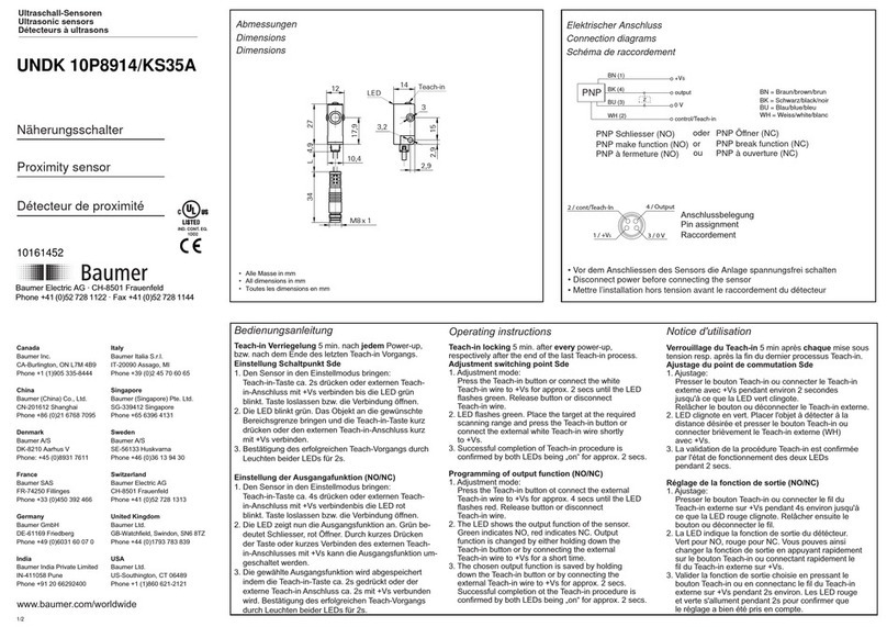
UNDK 09U6914/KS35A
11011518
1/3
IND. CONT. EQ.
1DD2
Ultraschall-Sensoren
Ultrasonic sensors
Détecteurs à ultrasons
Distanz messender Sensor
mit Analogausgang 0 - 10 V
Distance measuring sensor
with analog output 0 - 10 V
Détecteur de mesure avec
sortie analogique 0 - 10 V
Canada
Baumer Inc.
CA-Burlington, ON L7M 4B9
Phone +1 (1)905 335-8444
China
Baumer (China) Co., Ltd.
CN-201612 Shanghai
Phone +86 (0)21 6768 7095
Denmark
Baumer A/S
DK-8210 Aarhus V
Phone: +45 (0)8931 7611
France
Baumer SAS
FR-74250 Fillinges
Phone +33 (0)450 392 466
Germany
Baumer GmbH
DE-61169 Friedberg
Phone +49 (0)6031 60 07 0
India
Baumer India Private Limited
IN-411058 Pune
Phone +91 20 66292400
Italy
Baumer Italia S.r.l.
IT-20090 Assago, MI
Phone +39 (0)2 45 70 60 65
Singapore
Baumer (Singapore) Pte. Ltd.
SG-339412 Singapore
Phone +65 6396 4131
Sweden
Baumer A/S
SE-56133 Huskvarna
Phone +46 (0)36 13 94 30
Switzerland
Baumer Electric AG
CH-8501 Frauenfeld
Phone +41 (0)52 728 1313
United Kingdom
Baumer Ltd.
GB-Watchfield, Swindon, SN6 8TZ
Phone +44 (0)1793 783 839
USA
Baumer Ltd.
US-Southington, CT 06489
Phone +1 (1)860 621-2121
www.baumer.com/worldwide
Baumer Electric AG · CH-8501 Frauenfeld
Phone +41 (0)52 728 1122 · Fax +41 (0)52 728 1144
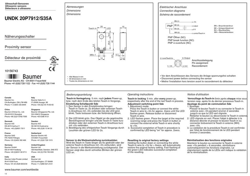
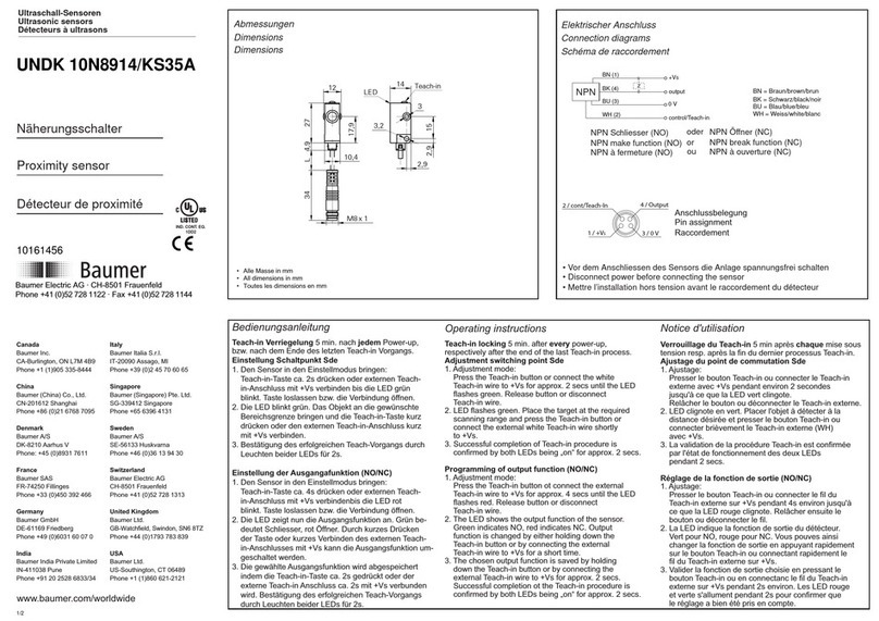
Abmessungen
Dimensions
Dimensions
48,8
48
15 15
2,95
30
20,5
30,45
10,2
19,9
6,5
14,5
8,2
3,5
2xø
3,2
ø
17,4
3,25 36,75
Teach-in
8,6
LED*
24,5
3x M3x5,8
2,5
4xø
LED*
8,9
44,8
3,9
13,8
*LED visible from opposite only
3,22x ø
3,22x ø
23,6
.ac 43 L
M8 x 1
• Alle Masse in mm
• All dimensions in mm
• Toutes les dimensions en mm
Elektrischer Anschluss
Connection diagrams
Schéma de raccordement
output
0V
BN (1)
BK (4)
BU (3)
+VS
Z
Analog
WH (2) control/Teach-in
BN = Braun/brown/brun
BK = Schwarz/black/noir
BU = Blau/blue/bleu
WH = Weiss/white/blanc
• Vor dem Anschliessen des Sensors die Anlage spannungsfrei schalten
• Disconnect power before connecting the sensor
• Mettre l’installation hors tension avant le raccordement du détecteur
Anschlussbelegung
Pin assignment
Raccordement
1 / +VS3 / 0 V
4 / Output
2 / cont/Teach-In
Befestigungsarten
Fixing modes
Types de fixation
• Alle Masse in mm
• All dimensions in mm
• Toutes les dimensions en mm
Screw M3
Machine support
UNDK 09U6914/KS35A
2/3
Technische Daten
Technical data
Données techniques
Betriebsspannungsbereich Vs Plage de tension Vs
Stromaufnahme max. (ohne Last) current consumption max. (no load) Consommation max. (sans charge)
Max. Laststrom Max. load current Courant de charge max.
Kurzschlussfest Short circuit protection Protégé contre courts circuits
Ausgangsanzeige Output state indication Indication de l’état de sortie
Schutzklasse Protection class Classe de protection
Verpolungsfest
Temperaturbereich
Voltage supply range Vs
Reverse polarity protection
Temperature range
Protégé contre inversion de polarité
Température de fonctionnement
IP67
0...60°C
LED gelb-rot/yellow-red/jaune-rouge
ja/yes/oui
ja/yes/oui
15mA
<=35mA
15-30VDC (UL-Class 2)
0,5 Nm
Siehe Betriebsanleitung auf www.baumer.com See manual on www.baumer.com Voir le manuel sur www.baumer.com
<= 2 % Sde
< 0.5 mm
(siehe Dok./see doc./consultez doc.)
30...200 mm
30...200 mm
Couple de serrage max.
Dérive en température
Reproductibilité
Faisceau sonore
Val. fin. de portée de dét. Sde
Val. ini. de portée de dét. Sdc
Maximum installation torque
Temperature drift
Repeatability
Sonic cone profile
Scanning range far limit Sde
Scanning range close limit Sdc
max. Anzugsdrehmoment
Temperaturdrift
Reproduzierbarkeit
Schallkeule
Erfassungsbereich-Endwert Sde
Erfassungsbereich-Startwert Sdc
General information
Informations supplémentaires
Weitere Erläuterungen
Hinweise
Notes
Notes
Einschaltdrift
Dieser Sensor unterliegt einer Einschaltdrift.
Diese Drift wird ca. 15 min nach Anlegen von
+Vs kompensiert.
Power-up drift
This sensor is subject to a „power-up drift“.
The drift is compensated for after a warm-up
time of approximately 15 min.
Dérive de l'alimentation
Ce détecteur est sujet à une “dérive à l’enclenchement“.
Cette dérive est compensée 15 min environ après
l’enclenchement.
Externen Teach-In nicht verwendet
Wird der externe Teach-In Eingang nicht
verwendet, muss er auf GND gelegt
werden.
External Teach-In not used,
If external Teach-In option is not used, the
Teach-In wire must be attached to GND.
Teach-in externe non utilisé
Dans le cas ou le Teach-in externe n’est
pas utilisé, il faut le raccorder avec GND.
Technische Änderungen vorbehalten Technical specifications subject to change Sous réserve de modifications techniques
UNDK 09U6914/KS35A
3/3
Taste 2 s betätigen
Press the button for 2 s
Appuyer sur le bouton pendant 2 s
Objekt an der „Startwert“
Position platzieren (0V)
Place the object at the „close limit“
position (0V)
Place l'object dans la
„valeur initiale“ (0V)
Teach-in Erfassungsbereich analog
Teach-in scanning range analog
Teach-in plage de détection analogique
Auf Werkseinstellung zurücksetzen
Reset to factory settings
Réinitialisation des réglages d'usine
Taste 6 s betätigen
Press the button for 6 s
Appuyer sur le bouton
pendant6 s
Gelbe LED blinkt (2 Hz)
Yellow LED flashing (2 Hz)
LED jaune clignote (2 Hz)
Gelbe LED leuchtet kurz
Yellow LED on briefly
LED jaune s'allume brièvement
Gelbe LED blinkt (2 Hz)
Yellow LED flashing (2 Hz)
LED jaune clignote (2 Hz)
Umkehrung der Ausgangsfunktion 10...0V
Wie Vorgang 0...10V, aber Punkte 2 und 4 tauschen.
Adjustment of 10...0V output function
According to process 0...10V, swap step 2 and 4.
Inversion de la fonction de sortie 10...0V
Comme pour le processus 0...10V mais en inversant l'ordre 2 et 4.
1
2
3
4
5
Gelbe LED blinkt (2 Hz)
Yellow LED flashing (2 Hz)
LED jaune clignote (2 Hz)
Taste kurz betätigen (>200 ms)
Press the button briefly (>200 ms)
Appuyer brièvement sur le bouton
(>200 ms)
Taste kurz betätigen (>200 ms)
Press the button briefly (>200 ms)
Appuyer brièvement sur le bouton
(>200 ms)
Objekt an der „Endwert“
Position platzieren (10V)
Place the object at the
„far limit“ (10V)
Place l'object dans la „valeur
finale“ (10V)
Teach-in Vorgang / Teach-in procedure / Procédure Teach-in
Gelbe LED 2s ein=erfolgreich
Gelbe LED blinkt 16 Hz=fehlgeschlagen
Yellow LED for 2s on=successful
Yellow LED flashing 16 Hz=failed
LED jaune s'allume pendant 2 s=succès
LED jaune clignote 16 Hz=échouer
Gelbe LED blinkt (16 Hz), bei Los-
lassen der Taste leuchtet LED 2 s
Yellow LED flashing (16Hz), on
release of button LED for 2 s on
La LED jaune clignote (16 Hz),
après relâchement du bouton, la
LED s’allume pendant 2 s
Wichtige Hinweise
- Messmodus: Gelbe LED blinkt = Empfangssignal schwach. Mögliche Massnahmen: Objekt neu teachen; Sensor näher beim Objekt platzieren; Transducer reinigen
- Messmodus: Rote LED leuchtet = Objekt im Blindbereich
- Zum Teachen kann analog zur Taste auch die Teach-in Leitung verwendet werden, indem diese mit +Vs verbunden wird
- Teach-in Modus: Tastenbetätigung wird über den Signalausgang mit zeitlich gleichem high- Signal (10V) bestätigt. Ist Teach-in Vorgang nicht erfolgreich, ist das Ausgangssignal ca. 2 s high (10V)
- Bei Fehlschlagen des Teach-in Vorganges werden die zuletzt erfolgreich gespeicherten Einstellungen aktiv
- Teach-in Modus: Erfolgt 60 s keine Aktion, wechselt der Sensor ohne Speichern in den Messmodus zurück
- Verriegelung der Teach-in Taste 5 min nach Power-up bzw. nach Ende des letzten Teach-in Vorganges. Die Teach-in Leitung bleibt aktiv
1
Important information
- In measuring mode: Yellow LED flashing = weak signal received. Conceivable corrective measures: teach object anew; move object closer to sensor; clean transducer
- In measuring mode: Red LED on = object within blind range
- Sensor can also be teached remotely by using the white Teach-in wire instead of the Teach-in button. Just connect with +Vs following the sequencing instructed
- In Teach-in mode: activation of button is confirmed by the output being high (10V) for as long as the button is held down. If Teach-in has not been successful the output is high (10V) for approximately 2s
- Provided the Teach-in sequence cannot be successfully completed the sensor defaults automatically to the previously saved settings
- In Teach-in mode: provided there is no input for 60s the sensor changes into measuring mode without saving
- The Teach-in lock is active 5 min after power-up or after the end of the last Teach-in process. The remote Teach-in wire (WT) remains active
Renseignements importants
- Mode de mesure: LED jaune clignote = faible signal de réception. Mesures possibles: nouvel apprentissage de l’objet; placer l’objet plus près du détecteur; nettoyer le transducteur
- Mode de mesure: LED rouge s’allume = objet dans la zone aveugle
- Pour l’apprentissage et à la place du bouton, on peut également utiliser la ligne Teach-in en la raccordant avec +Vs.
- Mode d’apprentissage: en appuyant sur le bouton, on reçoit la confirmation immédiate par un signal de sortie identique high (10V). Si le processus Teach-in n’a pas pu être mené à bien, le signal de sortie
reste high pendant 2 sec (10V)
- Lorsque le processus de Teach-in échoue, les derniers réglages mémorisés avec succès sont à nouveau actifs
- Mode Teach-in : si aucune action ne se produit endéans 60 s, le détecteur revient, sans mémorisation, au mode de mesure
- Verrouillage du Teach-in : 5 min après mise sous tension, respectivement à la fin du dernier processus Teach-in. La ligne Teach-in reste active
Other Baumer Accessories manuals

Baumer OADM 20U2472/S14C User manual

Baumer

Baumer OADM 20U2472/S14C User manual

Baumer FKDM 22P1902/S14F User manual

Baumer

Baumer FKDM 22P1902/S14F User manual

Baumer O200 User manual

Baumer

Baumer O200 User manual

Baumer FKDM 22N1901/S14F User manual

Baumer

Baumer FKDM 22N1901/S14F User manual

Baumer 10142521 User manual

Baumer

Baumer 10142521 User manual

Baumer UNAR 18N6903/S14G User manual

Baumer

Baumer UNAR 18N6903/S14G User manual

Baumer GIM140R User manual

Baumer

Baumer GIM140R User manual

Baumer URDK 10N8914 User manual

Baumer

Baumer URDK 10N8914 User manual

Baumer Clever Level LBFH User manual

Baumer

Baumer Clever Level LBFH User manual

Baumer OM70-11216510 User manual

Baumer

Baumer OM70-11216510 User manual

Baumer URDK 30P7104/S14 User manual

Baumer

Baumer URDK 30P7104/S14 User manual

Baumer UNAM 12I9914/S14D User manual

Baumer

Baumer UNAM 12I9914/S14D User manual

Baumer 10161026 User manual

Baumer

Baumer 10161026 User manual

Baumer UNDK 20N7912/S35A User manual

Baumer

Baumer UNDK 20N7912/S35A User manual

Baumer UNDK 20N7914/S35A User manual

Baumer

Baumer UNDK 20N7914/S35A User manual

Baumer UNDK 20P6912/S35A User manual

Baumer

Baumer UNDK 20P6912/S35A User manual

Baumer UNAM 12N1914/S14 User manual

Baumer

Baumer UNAM 12N1914/S14 User manual

Baumer UNAM 12P3912/S14 User manual

Baumer

Baumer UNAM 12P3912/S14 User manual

Baumer CombiTemp TFRH User manual

Baumer

Baumer CombiTemp TFRH User manual

Baumer OADM 21I6480/S14F User manual

Baumer

Baumer OADM 21I6480/S14F User manual

Baumer OHDM 16P5651 User manual

Baumer

Baumer OHDM 16P5651 User manual

Baumer FEDK 07N6901/KS35A User manual

Baumer

Baumer FEDK 07N6901/KS35A User manual

Baumer FVDK 10P66Z0 User manual

Baumer

Baumer FVDK 10P66Z0 User manual

Baumer UNAR 18P6912/S14G User manual

Baumer

Baumer UNAR 18P6912/S14G User manual

Popular Accessories manuals by other brands

Dometic REVO ZIP 200 Installation and operating manual

Dometic

Dometic REVO ZIP 200 Installation and operating manual

EnOcean 02LINE TRI02SYS Installation and operating manual

EnOcean

EnOcean 02LINE TRI02SYS Installation and operating manual

Outdoor Revolution Oxygen Speed 3 Instructions & care manual

Outdoor Revolution

Outdoor Revolution Oxygen Speed 3 Instructions & care manual

Waterpik Express user manual

Waterpik

Waterpik Express user manual

SMC Networks PSE530 Series Installation & maintenance manual

SMC Networks

SMC Networks PSE530 Series Installation & maintenance manual

Cornelius 0 installation manual

Cornelius

Cornelius 0 installation manual

Logitech CRAYON Setup guide

Logitech

Logitech CRAYON Setup guide

Roach Conveyors 138LRC owner's manual

Roach Conveyors

Roach Conveyors 138LRC owner's manual

Rock empire Omega Instructions for use

Rock empire

Rock empire Omega Instructions for use

Knocks KDDM-2 operating instructions

Knocks

Knocks KDDM-2 operating instructions

Family Care Accu FC2631 user manual

Family Care Accu

Family Care Accu FC2631 user manual

SOLIS THERMOSOFT user manual

SOLIS

SOLIS THERMOSOFT user manual

Nexa LMLR-710 quick start guide

Nexa

Nexa LMLR-710 quick start guide

Daktronics BA-1518-11 Installation, Maintenance, and Specifications Manual

Daktronics

Daktronics BA-1518-11 Installation, Maintenance, and Specifications Manual

ABB Ability Smart Sensor Installation guidelines

ABB

ABB Ability Smart Sensor Installation guidelines

Siko LEC100 Translation of the original installation instructions

Siko

Siko LEC100 Translation of the original installation instructions

TS Optics TSLA manual

TS Optics

TS Optics TSLA manual

Levana OmaSense quick start guide

Levana

Levana OmaSense quick start guide

manuals.online logo
manuals.online logoBrands
  • About & Mission
  • Contact us
  • Privacy Policy
  • Terms and Conditions

Copyright 2025 Manuals.Online. All Rights Reserved.