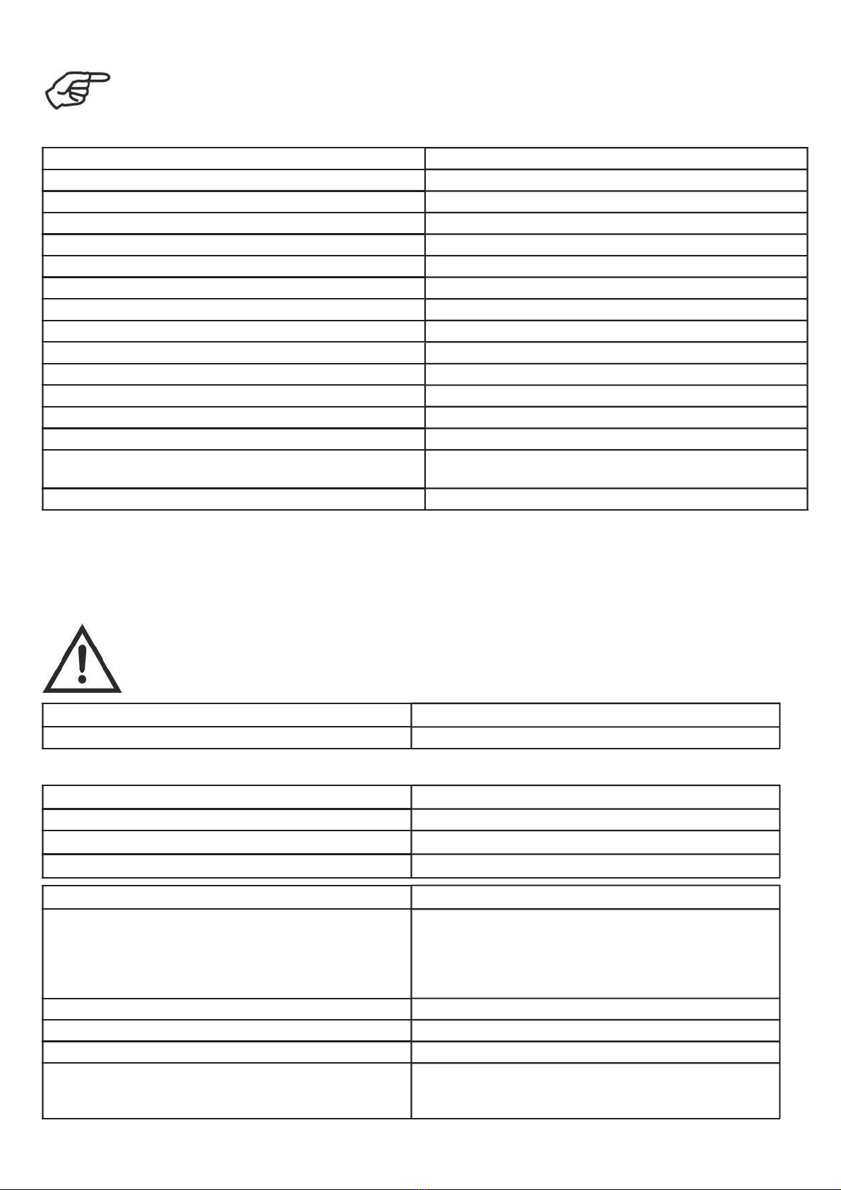
DKL D2-SAE User manual

Operating Instructions
Manufacturer:
DKL CHAIRS GmbH
An der Ziegelei 3
D-37124 Rosdorf
Germany
+49 (0)551-50060
www.dkl.de
Form no. GEN-D2SAE
Rev. 04 / 10.08.2023
Subject to change without
notice.
D2-SAE

2
Contents
Annex
> Operating Instructions DÜRR Dental Spittoon valve 3
> Operating Instructions DÜRR Dental CAS 1 Combi-Separator
> Operating Instructions DÜRR Dental CS 1 Combi-Sepamatic
> Use Manual Syringe Luzzani Minilight
> USER MANUAL FARO EVA
Symbols in the Operating Instructions 3
Symbols inside the Unit 4
Introduction 5
Electromagnetic Compatibility (EMC) 6
Safety Notes – General 7
Safety Notes – Assistant’s device and Water unit 8
Technical Specifications 9
Media Requirements 10
Dimensions in Millimetres 12
Product Description 13
Moving the Treatment Chair 15
Putting the Treatment Unit into Operation 17
Function Syringe Luzzani Minilight 18
Operating Lamp LED.light EVA 19
Tray 22
Cuspidor 23
Suction 24
Suction System 25
Cleaning and Disinfection of the Suction Handpieces 26
Cleaning and Disinfection of the Suction System 28
Cleaning and Disinfection of the Surfaces 30
Cleaning and Disinfection of the Instrument Holders 33
Bottle Care System 34
Flushing Function with the Bottle Care System 35
Intensive Flushing with the Bottle Care System 35
Water Separation Unit (WSU) 36
Flushing Function with the Water Separation Unit (WSU) 38
Intensive Flushing with the Water Separation Unit (WSU) 38
Filling DK-DOX 150 into the Water Separation Unit 39
Maintenance and Inspection 40
Safety Inspections 40
Warrantee Declaration + Waste Disposal 41
EMC - Manufacturer‘s Declaration 42

3
Symbols in the Operating Instructions
WARNING!
(risk of injury)
General explanations,
without risk to
persons or objects
Thermodisinfectable Sterilisable up to the
specified temperature Call customer service!
CAUTION!
(to prevent
damage occurring)
Symbols on the unit
Consult instructions for
use or consult electronic
instructions for use
ON / OFF Do not dispose of with
household waste
CE-marking with iden-
tification number of the
notified body
Type B application part
Manufacturing date Model (designation) Serial number
VElectrical voltage VA
AC
AHz
Electrical power con-
sumption
Current intensity Frequency of alter-
nating current
Electrical fuse
Alternating current
Foot controller
Manufacturer Medical device UDI - Product
Identification

4
Symbols inside the Unit
Earth conductor connection -
Protective earth
Functional
earth
Symbols on the packaging
Transport upright; top
Permissible temperature range
Air humidity, limitation
Protect from moisture!
Do not stack!
Fragile
N
Connection point for
neutral conductor
Atmospheric pressure limitation

5
Introduction
For your safety and the safety of your patients
These operating instructions are intended to explain how to use your product. However,
we must also warn of possible dangerous situations. Your safety, the safety of your team
and, of course, the safety of your patients are very important to us.
Please observe the safety instructions!
Intended purpose
This treatment unit is used for the diagnosis and therapy of children and adults in the field of dentistry.
Improper use can damage the treatment unit and thus pose risks and
hazards to the patient, user and third parties.
Qualification of the user
The DKL treatment unit may only be used after medically, professionally and practically trained
personnel have been instructed. The development and design of the treatment unit were geared
towards the target group of dentists, dental hygienists, qualified dental employees (prophylaxis) and
dental assistants.
Production according to EU directive
The medical device complies with the provisions of regulation (EU) 2017/745.
0123
Responsibility of the manufacturer
The manufacturer can only be held responsible for the impact on the safety,
reliability and performance of the treatment unit if the following instructions
are observed:
> The dental unit must be used in accordance with these operating
instructions.
> If assembly, additions, new settings, changes or repair work is carried out
by DKL or trained technicians authorised by DKL or personnel of authorized
dealers trained by DKL.
> The electrical installation of the room must comply with the regulations of
the IEC 60364-7-710 standard („Erection of electrical installations in rooms
used for medical purposes“) or comply with the regulations applicable in
your country.
> The recommended annual maintenance is carried out and any repair work
in this context meets the requirements of EN 62353.
> „Repeat tests and pre-commissioning tests of medical electrical equipment
and systems – general regulations“are fully complied with.
> The national legal regulations are observed when using the device, in
particular the applicable health and safety regulations and accident
prevention measures.

6
Electromagnetic Compatibility (EMC)
Medical electrical equipment is subject to special precautions with regard to EMC and
must be installed and commissioned in accordance with the EMC instructions. DKL
guarantees that the dental unit complies with the EMC guidelines only if original DKL
accessories and spare parts are used. The use of accessories and spare parts not
approved by DKL may lead to an increased emission of electromagnetic interference or
to a reduced resistance to electromagnetic interference.
The EMC manufacturer declaration can be found on page 42.
HF communication equipment
Do not use portable and mobile HF-communication equipment (such as mobile
telephones) during operation. These can affect medical electrical devices.
Risks due to electromagnetic fields
The functionality of implantable systems, such as cardiac pacemakers and
implantable cardioverter defibrillators (ICD), can be influenced by electric, magnetic and
electromagnetic fields.
> Before using the product, ask the patient and user about implanted systems and
check the use.
> Perform a risk-benefit analysis.
> Do not place the product near implanted systems.
> Do not place the instruments on the patient‘s body.
> Take appropriate emergency precautions and respond immediately to health changes.
> Symptoms such as increased heart rate, irregular pulse, and dizziness may be signs
of problems with a pacemaker or ICD.

7
Safety notes – General
> Before being put into initial operation, the treatment unit must be kept at room
temperature for 24 hours.
> Before each application, check the treatment unit and the instruments with cables for
damage and loose parts.
> Do not operate the treatment unit if it is damaged.
> Check the set parameters each time you restart the unit.
> Carry out a test run before each application.
> The application and timely shutdown of the system is the user’s responsibility.
> Make sure that in the event of a device or instrument failure, the treatment can be
completed safely.
> Use only original DKL fuses.
> Never touch the patient and the electrical connection at the treatment unit at the same
time.
> Do not lean on the the assistant‘s device, the tray or the operating lamp.
> When moving the treatment chair, the doctor‘s device, the assistant‘s device, the tray or
the operating lamp, pay attention to the patient and the practice personnel.
> Always switch off the treatment unit before leaving the practice.
Hygiene and care before using the device
> Clean and disinfect the device immediately before or after each treatment!
> Wear protective clothing.
The treatment unit is classified as an „ordinary device“ (closed device without protection
against water ingress).
The treatment unit is not suitable for use in an explosive atmosphere or in explosive
mixtures of anaesthetics with oxygen or nitrous oxide.
The treatment unit is not suitable for use in rooms with an oxygen enriched atmosphere.
Safety notes – Patient chair
> Not suitable for patients who cannot remain in a resting position due to mental or
physical disabilities.
> The patient‘s arms and legs must rest on the upholstered parts of the chair.
> Do not exceed the maximum patient weight of 150 kg.
> Do not sit on the head or foot rest of the horizontally aligned patient chair.
> Position changes must always be carried out under the surveillance of the person
giving treatment.
> Watch patients while moving the treatment chair.
> Make sure that there are no objects under the treatment chair.
Observe your country-specific guidelines, standards and specifications for
cleaning, disinfection and sterilisation.

8
> Before putting the device into initial operation and after downtimes (weekends,
(public) holidays etc.), flush the water lines intensively.
> Flush all instrument connections for 2 minutes before starting work.
> Press the glass fill button several times before starting work.
> Rinse used instruments for 20 seconds after each treatment.
Risk of injury or infection caused by instruments that are not in use:
The arrangement of the instruments may cause injury or infection to the hand and
forearm when accessing the tray or the display.
Therefore, when accessing the tray or the display, pay attention to the arrangement of
the instruments.
> Do not exceed the maximum permissible load of 2 kg on the assistant’s
device.
Highly immunosuppressed patients or patients with specific lung diseases should not
get into contact with the water of the treatment unit.
It is recommended to use sterile solutions.
Safety notes – Assistant’s device and Water unit

9
Weight
D2-SAE max. 225 kg
Transport and storage conditions
Ambient temperature -30 to +70 °C
Relative humidity 10 to 80 %
Atmospheric pressure 500 hPA to 1060 hPa
Operating conditions
Quality and load-bearing capacity of the floor The floor must be level and horizontal according to EN
18202. Unevenness of the floor along the total length of
the chair base up to 2 mm is acceptable. The minimum
load-bearing capacity of the floor must be 0.5 N/cm2
(equivalent to approx. 500 kg/m2).
Ambient temperature 10 to 35 °C
Relative humidity 15 to 80 %
Atmospheric pressure 700 hPA to 1060 hPa
Installation site ≤ 3,000 m above sea level
The treatment unit is not suitable for operation in
hazardous areas.
Technical Specifications
Supply voltage 230V AC
Nominal voltage max. 3 A
Frequency 50/60 Hz
Fuse T 6.3 A H 250 V primary
Maximum power consumption 625 VA
Device class according to MDR (EU) 2017/745 IIa
Protection class Device of protection class I
Contamination level 2
Over voltage category II
Power cable 3x1,5 mm2
Suction control lines to the suction device 5x1,5 mm2
Potential equalisation 1x 4 mm2
Relay control line optional special function 3x1,5 mm2
Free end electrical cables above floor 500 mm
Fuse for domestic installation Circuit breaker: 16 A medium-lag
Recommendation: circuit breaker type C
Degree of protection against ingress of water Ordinary device (without protection against water ingress).
Permanently connected device. In order to avoid the risk of electric shock, this device may only
be connected to a power supply with an earth conductor.
The motors of the treatment unit are designed for intermittent operation in accordance with the
dental treatment method.
Driving motors for patient chair and backrest: duty cycle (max. 25 s „ON“ / 400 s „OFF“).

10
Media water
Water hardness 1.5 to 2.14 mmol/l = 8,4-12 dH
ph-value 6,5 to 8,5
Water filtration on site ≤ 100 µm
Water inflow Pipe 10x1mm, angle valve outlet 3/8“
Water connection above floor min. 40 mm, max. 60 mm
Water inlet pressure 2.0 to max. 6.0 bars
Water quality Cold water in accordance with local and national drinking
water regulations.
Minimum flow rate 3 l/min
Media air
Air inlet pressure max. 7 bars
Air consumption 80 Nl/min
On-site air filtration ≤ 100 particles size 1 - 5 μm referred to one m3of air
Oil content ≤ 0.5mg/m3,oil-free compressors; the compressor must suck
in hygienically perfect air.
Humidity Pressure dew point ≤ -20 °C at atmospheric pressure
Compressed air supply Pipe 10x1 mm, angle valve outlet 3/8“
Air connection above the floor min. 40 mm, max. 60 mm
Media Requirements
• Perform the installation according to the national installation requirements (e.g. EN 1717).
• For the reduction of microorganisms in the water supply pipe, please observe the following when laying this pipe to the
treatment unit:
- Avoid long stub lines to the treatment unit.
- Select the installation in such a way that other essential consumers (e.g. washbasin) are as far as possible
behind the connection of the treatment unit can be supplied from the same pipe.
- Avoid laying the hot water supply pipes in parallel.
• Recommendation: For the water supply of the treatment unit, install an angle valve with 2 outlets and 2 stop cocks. The
second outlet allows easy sampling of water for microbiological analysis.
Clean air and water pipes before installing the unit.
Chips and other foreign substances could be flushed or blown into the treatment unit.
Metal chips can interfere with the function of pneumatic components. Filters are clogged by foreign substances.
• When assembling, make sure that there are no chips or other foreign substances in the pipes.
• Flush the water pipes.
• Blow out the air ducts.
• Make sure that no further foreign substances get into the pipes and ducts after rinsing or blowing out.
Before the treatment unit is installed, the microbiologically perfect water quality of the domestic water supply
should be ensured and documented in the form of a microbial count.
Sampling and microbial count should be carried out by a competent laboratory.
Connection to the public drinking water supply
The treatment unit with a water separation unit complies with the requirements of EN 1717 (free outlet with separation
distance ≥ 20 mm) and the DVGW (German Technical and Scientific Association for Gas and Water). It is intrinsically safe
in accordance with worksheet W540 and therefore also meets the requirements of W270 and KTW (guideline for hygienic
assessment of organic materials in contact with drinking water).
When the treatment unit is equipped with a cuspidor, the bowl rinser ensures the free outlet with a separation distance
≥ 20 mm. When the treatment unit is equipped with a Bottle Care System, the spray supply of the instruments is separate
from the public water supply.

11
Requirements for the suction system
Vacuum at supply connection min. 0,12 bar, max. 0,18 bar
Minimum suction power at supply connection ≥750Nl/min
Suction system Type 1: high flow rate
wet or dry suction
Diameter of suction handpieces: small suction handpiece: 6 mm
large suction handpiece: 16 mm
Suction pipe DN40 HT-PP (polypropylene, inside diameter approx. 36.5 mm)
Water drain DN40 HT-PP (polypropylene, inside diameter approx. 36.5 mm)
Gradient Min. 10 mm per metre
Wastewater volume 3 l/min
Filter in the treatment unit maintenance interval Article number
Particle filter water inlet 50 μm Replace annually 210623-WBG
Particle filter compressed air inlet 50 μm Replace annually 210623-LBG
Solid particle filter for the suction
system
Mesh size 1 mm In case of damage,
replace at least annually.
514100
1Air: pipe min. 10x1 mm, angle valve outlet 3/8“
2Water drain DN40 HT-PP
3Suction line DN40 HT-PP
4Power cable 3x1.5 mm2
4Equipotential bonding 1x 4 mm2
4Control line to suction device 5x1.5 mm2
5Water: pipe min. 10x1 mm, angle valve outlet 3/8“
(2 outlets with 2 stopcocks)
Requirements for Supply Connections
Typical pressure in the suction system
Spray mist suction Vacuum / mbar
90 NL/min 22,6
150 NL/min 38,2
200 NL/min 60,0
250 NL/min 88,8
300 NL/min 124
316 NL/min 137
Saliva ejector
50 NL/min 100,0
55 NL/min 120,0
60 NL/min 135,2
67 NL/min 162
80 NL/min 200
Media Requirements

12
Dimensions in Millimetres
Treatment chair:
lowest position 395 mm
highest position 730 mm

13
Product Description
Identification
label
1Treatment chair, seat
2Treatment chair, back rest
3Treatment chair, double-jointed headrest
4Treatment chair, joystick
5Treatment chair, arm rest
6Cuspidor
7Assistant’s device
8Tray
9Operating Lamp LED.light EVA

14
Marking Type of holder
GS Spray mist suction
KS Saliva ejector
S Syringe
Connecting the instrument hoses:
The instrument hoses can be connected or disconnected via a plug connection under
the assistant’s device. The assistant’s device is equipped with the following instruments
(from the left): 3-function syringe, spray mist suction and the saliva ejector. The instru-
ment holders are marked on the back. Do not connect the tubes crosswise.
Product Description
1Spray mist suction
2Saliva ejector
33-function syringe

15
Joystick
Programme keys
Moving the Treatment Chair
Move the joystick downwards
> Treatment chair moves downwards.
Move the joystick upwards
> Treatment chair moves upwards.
Move the joystick to the left
> Back rest tilts backwards.
Move the joystick to the right
> Back rest moves to an upright position.
Tap the JoystickTwice
> Treatment chair moves to the entry /exit position.
Tap the joystick twice downwards
> Treatment chair moves to the treatment position p2.
Tap the JoystickTwice to the Left
> Treatment chair moves to the rinsing position and
back to the last position when tapping twice again.
Tap theJoystickTwice to the Right
> Treatment chair moves to the treatment position p1.
Press “p0“
> Treatment chair moves to the position for getting on/off.
Press “p1“
> Treatment chair moves to treatment position p1.
Press “p2“
> Treatment chair moves to treatment position p2.
Press “p3“
> Treatment chair moves to treatment position p3.
Briefly press “lp“
> Treatment chair moves to the rinsing position and after
renewed pressing back to the “last position”.
For programming the keys, move to the desired programme position manually and then keep the respective
programme key pressed for about 3 seconds until you hear a signal tone. Now you have successfully saved
your individual treatment position.
Saving programme keys p0 – p3
Press the ”lp“ key to move the chair to the rinsing position. By pressing the key “Ip” once again, the chair moves
back to the previous programme position or to the manually set position. In order to programme the chair, move
it manually to the desired rinsing position and then keep the key “Ip” pressed for about 3 seconds until you hear
a signal tone. Now you have successfully saved your rinsing position.
Saving programme key lp
Programme keys at the back rest
Joystick at the chair base
Emergency-Stop System
Briefly tap the joystick or any programme key at the back rest to stop the active program-
me immediately.
Programme Run
Press the programme keys “0” and “lp” simultaneously for about 3 seconds until you hear
a signal tone. The treatment chair then moves the seat and the back rest into the lowest
position. The motion sequence has been reset now.
Once an instrument has been activated, the treatment chair cannot be moved any more.

16
Moving the Treatment Chair
You can find an application film at www.youtube DKL Germany.
Video: DKL CHAIRS D2 SERIES FUNKTIONEN UPHOLSTERY POSITIONS
LINK: https://youtu.be/o307-rWGp5A
To facilitate getting on or off the chair, the right arm
rest (optional) can be swivelled by 90°.
Manually extractable double-jointed head
rest.
Pull the release lever up to freely adjust the double-
jointed head rest. Press the lever down to fix the
position of the double-jointed head rest. The release
lever must always be pulled up completely to move
the head rest.
When moving the back rest, there is a risk of injury
or crush. The patient’s hands and arms must always
rest on the chair upholstery.

17
Putting the Treatment Unit into Operation
Putting the unit into operation
Before putting your treatment unit into initial operation, an intensive flushing
must be carried out (→ page 35 or page 38).
The treatment unit is equipped with a power switch 1on the chair base. The power switch connects
the treatment unit with the power supply.
In the event of longer downtimes, the treatment unit should be disconnected from the power supply.
The treatment unit contains a device fuse 2.
Switch on the treatment unit at the power switch.The power switch lights up green.
Activating /
Deactivating the
Treatment Unit
T 6,3A H 250V

18
Function Syringe Luzzani Minilight
See also operating instructions of the Luzzani company for their Minilight
syringe!
Symbol: Air
Symbol: Water Handpiece
Nozzle
Nozzle retainer Water Air
After each use on a patient, the handpiece and tip of the syringe MUST be cleaned and
sterilised to guarantee maximum hygiene.
To blow water into the operating
field, just press the left button on
the handpiece, symbol: water.
To insufflate air into the operating
field, just press the right button
on the handpiece, symbol: air.
To blow a combination of air and
water (spray), press both buttons
on the handpiece at the same
time.
Unscrew the
nozzle retainer.
Withdraw the
nozzle retainer.
Withdraw the
nozzle.
Press the pawl to release
the handpiece.
Withdraw handpiece.
You will find the
sterilisation procedure
on the handpiece.

19
Operating Lamp LED.light EVA
When swivelling and moving the
operating lamp, always make sure
that no objects or persons are in the
swivelling range of the arm system.
Otherwise, personal injury or pro-
perty damage may occur.
In order to move the operating lamp
only touch its handles!
For the intended use, please observe the operating instructions issued by FARO:
USER MANUAL EVA
Reflectors
Switch
Handles
Joystick
Indicator light
Mirror
Switching on/off on the joystick:
Push right or left
Decrease the light intensity on the joystick:
Push right and keep pushed until desired
intensity is reached.
Increase the light intensity on the joystick:
Push left and keep pushed until desired
intensity is reached.
light intensity indicator change in light intensity

20
Arbeitsfeldleuchte LED.light EVA
Composave am Joystick aktivieren:
Joystick nach vorne oder hinten
drücken.
Akustisches Signal
und die Anzeige
wechselt auf orange.
Composave am Schalter aktivieren:
Ein Klick.
Änderung der Farbtemperatur über den Schalter:
Bei jeder Ausführung eines Doppelklicks auf den Schalter
ändert sich die Farbtemperatur in Kelvin (Tk) des Lichts.
Das Verfahren wiederholen, bis die gewünschte Farbtem-
peratur an der Anzeige ansteht. 2 Pieptöne teilen dem
Benutzer mit, dass die Tk geändert wird.
Anzeige Gelb
4000 Kelvin
Anzeige Weiß
5000 Kelvin
Anzeige Blau
5700 Kelvin
Einstellung Composave
Spiegel
Vorne auf der Schutzkappe befindet sich eine
Kunststoffabdeckung, die durch leichten Druck
am oberen Ende gelöst wird.
Beim Umdrehen der Abdeckung kommt ein
Spiegel zum Vorschein. Den Spiegel auf der
Schutzkappe fixieren.
Einen Anwendungsfilm finden Sie auf www.youtube DKL Germany.
Video: DKL CHAIRS L2-D2 SERIE FUNKTIONEN ARBEITSFELDLEUCHTE EVA LED.LIGHT
LINK: https://youtu.be/QzynV0x5zg8
Table of contents
Other DKL Dental Equipment manuals
Popular Dental Equipment manuals by other brands

Fona
Fona XDG Service and installation manual

NSK
NSK S-Max PICO Operation manual

3Disc
3Disc Heron IOS user manual

OrthoAccel Technologies
OrthoAccel Technologies AcceleDent OPTIMA Directions for use

Dentsply Sirona
Dentsply Sirona Ceram.x Spectra ST Directions for use

Dentsply Sirona
Dentsply Sirona DAC Universal operating instructions