DMC Alphatron PT-100 User manual

PAGE1OF2
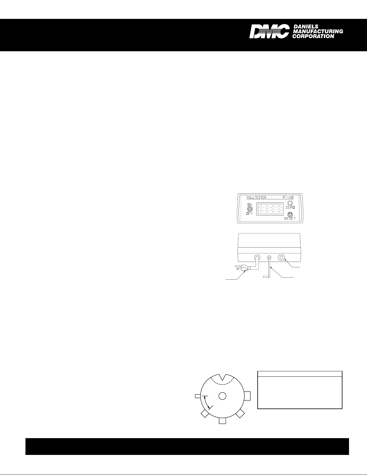
PT-100
WIRE CRIMP PULL TESTER
COPYRIGHT©2001 ALLRIGHTSRESERVED REV. B 05/01 FILE # DS0026 DOC # PT-100-DS
123
4
5
6
7
15
14
13
12
11
10 98
SLOT DIMENSION
No.
1
2
3
4
5
6
7
8
Size (in.)
.031
.250
.047
.236
.063
.218
.080
.203
No.
9
10
11
12
13
14
15
Size (in.)
.094
.188
.110
.172
.125
.158
.141
MAX MIN Dual Cam Action Grips
Upper Grips from 0 to .250" Diameter
Wire
UPPER GRIP
"Quick Grip"
LOWER GRIP
Standard Terminal Grip
1. SAFETY
The Alphatron PT-100 Wire Crimp Pull Tester is a force
measurementdevice,andoperatorsshouldwearsafetyglasses
for eye protection because foreign objects can be thrown from
the piece under test.
Topreventfireandshockhazard,donotexposethisequip-
ment to moisture. Always unplug the AC line cord prior to ser-
vicing.
Do not exceed the rated force capacity (100 lb., 45 kg.) of
the PT-100. The unit may be damaged, and the operator or
others in the immediate vicinity injured under extreme force
conditions.
2. SETUP
The Alphatron PT-100 is shipped from the DMC factory
assembled, calibrated, and tested. For best results, users
should familiarize themselves with the setup and operation of
the unit before placing it in service.
To operate, set the PT-100 on a flat, level surface in an
upright position. To prevent damage to the force sensing de-
vice, handle the unit by the main support post and base only.
Threemounting holesin thebase areprovided topermanently
bolt it in position, if desired.
Setthemeteralongsidethebase. Be careful to avoidstrain
on the cord between the meter and the load cell. The meter
has folding legs to permit the operator to adjust the viewing
angle.
3. OPERATION
With the switch on the front of the meter turned off, plug
the PT-100 into a 115VAC or appropriate outlet. Turn it on and
the display will light up to indicate that the unit is operational.
Allow 5 minutes warm-up prior to operating the unit. Zero the
display by alternatively turning the zero knob and momentarily
pressing the reset toggle. The display should read 00.0. It is
important to push the reset toggle before taking the next read-
ing. To select the correct "lower grip" slot for the wire/terminal
lead to be tested proceed as follows:
Rotate the grip to find the slot in which the lead wire fits
best. Select the slot that is the same width as the wire diam-
eter or one increment larger.
Insert the wire into the slot with the terminal down and
clear of the bottom surface of the "lower grip". Next, pass the
wire between the knurled upper grip cams and raise the lever
arm on the left hand grip to the "min" position to hold the wire
in place. Check to be sure that when you pull down on the
operating lever, the wire will be pulled as nearly vertical as
possible. Adjust the "lower grip" as necessary to make this
alignment.
Pull the operating lever downward in a slow and consis-
tent motion while holding the "upper grip" lever until its self
tightening action takes over. The indicator will begin to display
PT-100
DATASHEET
DANIELS MANUFACTURING CORP., 526 THORPE ROAD, ORLANDO, FL 32824, USA
DONOTEXCEEDTHE
RATEDFORCEOF100LB
BASE
METER
KNURLEDSURFACE ON O.D.
PAGE2OF2 REV. B 05/01 FILE # DS0026 DOC #PT-100-DS
1. Allow PT-100 to warm up for 5 minutes.
2. Depress the reset toggle momentarily.
3. Zero the display by alternatingly turning the zero knob
andmomentarily pressingthe resettoggle untilthe dis-
play reads 00.0.
4. Press the R-cal button on the back of the unit. Press
the reset toggle to zero the display. Repeat this pro-
cess several times to assure a repeatable value. The
display value (R-cal # X .005 = tolerance
R-cal # plus & minus tolerance = range)
should be within .5% of the value recorded on the bot-
tom of the unit.
EXAMPLE: R-cal = 81.0
81.0 X .005 = .40
80.6 to 81.4 = range
5. If anyof the procedures in steps 2-4 do not producethe
expected results, the unit should be returned to DMC
forrepair andrecalibration.
6. SERVICE
Repairand calibration servicesfor thePT-100 Wire Crimp
Pull Tester is available from Daniels Manufacturing Corpora-
tion. Spare parts are also available.
Shoulditbe necessary to returntheunit for service,please
ship to the address on this datasheet, freight prepaid. Enclose
aletter, or purchaseorderwithcompany name, address,phone
number, the individual to be contacted and the reason for re-
turn.
COPYRIGHT©2001 ALLRIGHTSRESERVED
NOTE: This option is made of heavier
duty material and is useful specifically
for testing ring terminals. It also offers
a universal "V" groove for testing non-
standard terminal sizes.
the amount of force exerted on the crimp. As the force is
increased the display will continue to update the reading until
the force is no longer increasing. (Usually this is the point at
which the crimp is pulled loose, or the wire breaks.)
Upon completion of the test, release the wire and press
the reset button on the display prior to the next test.
Best results are obtained with the PT-100 using a slow,
consistent motion when pulling the lever. A quick, or hesitant
motion can cause the wire to slip within the self tightening
cams and the terminal also may become unseated within the
slot.
4. CHANGINGTERMINAL GRIPS
CAUTION: ThePT-100 utilizes aprecision load cellfor
its force measurement. Care must be exercised when
changing grips not to create excessive side load on the
load cell sensor.
To change or replace the terminal grip complete the fol-
lowing steps in sequence.
1. To provide more room to work raise the rack and pinion
lever arm assembly as high as possible. Loosen the
large black knob on the left hand side of the assembly,
raise the assembly and retighten the knob.
2. Using a 9/64 in. hex key and an 11/32 in. open end
wrench, loosen and remove the 8-32 locking hex nut
from the bottom of the sensor assembly.
3. Remove the 8-32 x 1-1/2 in. screw, slip washer, termi-
nal grip and spacer from the sensor.
4. When installing the optional ring terminal grip, the re-
cessed center hole must face up for proper operation.
5. Reassemble in this order: Install slip washer on screw,
followed by the terminal grip, and spacer. Insert the
screw with this assembly through the hole in the sen-
sor.
6. Install 8-32 locking hex nut.
7. Using the hex key and open end wrench, tighten until
some effort is required to rotate terminal grip. This is
necessary to avoid play between the terminal grip and
the sensor.
8. Lower the rack and pinion lever arm assembly to its
operating level and tighten knob to secure.
5. FUNCTIONALCHECK
The PT-100 Wire Crimp Pull Tester is factory calibrated
with equipmenttraceable to the National Instituteof Standards
and Technology (NIST). We recommend recalibrating the unit
at intervals not to exceed one year in duration.
The funtional check is executed using the R-cal switch
built into the unit . The R-cal switch is located on the rear of
the unit, and its R-cal value is on the sticker applied to the
bottom of the unit.
A functional check can be performed at any time:
OPTIONAL RING TERMINAL GRIP
DATASHEET
DANIELS MANUFACTURING CORP., 526 THORPE ROAD, ORLANDO, FL 32824, USA
RING POSITION
1 Slot .200" to .03" @ .250" Depth
2 3/8" Dia. x .250" Pin
3 5/16" Dia. x .250" Pin
4 1/4" Dia. x .250" Pin
5 3/16" Dia. x .250" Pin
6 1/8" Dia. x .250" Pin
1
2
3
4
5
6
45° TYP.
LEADTOLOAD
CELL
R-cal
POWER
(115 VAC)
FRONTVIEW
REARVIEW
Other DMC Test Equipment manuals


