DMF RW-1630 Quick start guide

DIVERSIFIED METAL FABRICATORS, INC.
DMF 665 Pylant Street Atlanta, Georgia 30306
Service Department (404) 879-7882service@dmfatlanta.com
Phone (404) 875-1512 Fax (404) 875-4835info@dmfatlanta.com
http://www.dmfatlanta.com
Parts & Service Manual
RW-1630
&
RW-1630/50*
November 2017
SERIAL NUMBER (FRONT) ________________________
SERIAL NUMBER (REAR) ________________________
NOTE:
Please refer to the serial numbers when ordering parts or
inquiring about warranty items.
* This manual applies to both DMF’s RW-1630 Railgear, and DMF’s higher capacity
RW-1630/50 Railgear, including all configurations (standard, behind cab, and under cab)

DIVERSIFIED METAL FABRICATORS, INC. RW-1630
© 2017 DMF, Inc. All Rights Reserved.
Message from DMF
No matter what your job function is, Operation, Installation, Maintenance, or Repair, it is your
responsibility to familiarize yourself with the entire manual. Once you have read the entire
manual, there are some specific sections that you will want to pay special attention to,
depending on your role.
For purposes of this manual, we will refer to RW-1630 when discussing either RW-1630 or
RW1630/50, and we will explicitly call out any differences when appropriate.
If you find anything missing, incorrect or unclear in this manual, please contact us. We are
always trying to improve our manuals.
Manuals, service bulletins and general information are available on our website listed below.
We reserve the right to update our manuals without notice. You can download a current manual
at our website (http://www.dmfatlanta.com).
Thank you for choosing DMF Railgear. We make every effort to provide quality, safe and rugged
products for the railroad. We hope you'll find our gear to be satisfactory in every way. We take
product support very seriously, so if you have any questions, please contact us.
Contact:
Diversified Metal Fabricators
665 Pylant St. NE
Atlanta, GA 30306
(404) 875-1512
(404) 875-4835 Fax
(404) 607-1684 Parts
http://www.dmfatlanta.com
Ship to:
668 Drewry St. NE
Atlanta, GA 30306

DIVERSIFIED METAL FABRICATORS, INC. RW-1630
© 2017 DMF, Inc. All Rights Reserved.
TABLE OF CONTENTS
SECTION 1.0 GENERAL INFORMATION
1.1 General Description............................................. 1-2
1.2 Front Railgear .................................................... 1-3
1.3 Rear Railgear ..................................................... 1-5
SECTION 2.0 OPERATIONS
2.1 Before You Operate the Railgear ........................... 2-2
2.2 Anti-Lock Brake System (ABS).............................. 2-3
2.3 Highway Operation.............................................. 2-4
2.4 Getting on the Rail.............................................. 2-4
2.5 Getting off the Rail.............................................. 2-5
SECTION 3.0 ROUTINE MAINTENANCE
3.1 Inspection and Maintenance ................................. 3-2
3.2 Lubrication Specification ...................................... 3-3
3.3 Wheel Wear Gauge.............................................. 3-5
3.4 Troubleshooting.................................................. 3-7
3.4 Derailment......................................................... 3-8
SECTION 4.0 RAILGEAR INSTALLATION
4.1 Pre-Install.......................................................... 4-3
4.2 Initial Instructions............................................... 4-5
4.3 Installation of Rear Railgear ................................. 4-7
4.4 Varying Front Railgear Configurations .................... 4-13
4.5 Traditional Long Arm Assembly Installation............. 4-14
4.6 Cargo Arm Front Assembly Installations ................. 4-21
4.7 Completing Front Installation................................ 4-23
4.8 Under Cab Front Unit Installation .......................... 4-26
4.9 Behind Cab Front Unit Installation ......................... 4-30
4.10 Overall Alignment Procedure............................... 4-32
4.11 Rail Test .......................................................... 4-34
4.12 Final Weld-Out.................................................. 4-34
4.13 Install Decals.................................................... 4-36
4.14 Velcro Steering Wheel Lock................................. 4-37
4.15 Installation Review Checklist............................... 4-38
SECTION 5.0 RAILGEAR OPTIONS
5.1 Rail Sweeps ....................................................... 5-2
5.2 Pin-Off Options................................................... 5-3
5.3 Brakes .............................................................. 5-7
5.4 Two-Piece Wheels ............................................... 5-14
5.5 Stub Axle Shunts ................................................ 5-16
SECTION 6.0 HYDRAULIC SYSTEM
6.1 Hydraulic System................................................ 6-2
6.2 Valve Assemblies and Hydraulic Schematic ............. 6-4
6.3 Rear Hydraulic Cylinder Drawings.......................... 6-5
6.4 Front Hydraulic Cylinder Drawings......................... 6-9
6.5 Cylinder Assembly Procedures .............................. 6-11
6.6 Fitting Installation............................................... 6-12

DIVERSIFIED METAL FABRICATORS, INC. RW-1630
© 2017 DMF, Inc. All Rights Reserved.
SECTION 7.0 REAR RAILGEAR PARTS
7.1 Before Ordering Parts – Rear Railgear.................... 7-2
7.2 Rear Parts Detail Drawing .................................... 7-4
7.3 RW-1630 Pin-Off Orientation ................................ 7-5
7.4 Link Dimensions ................................................. 7-6
7.5 Extra-Short Links................................................ 7-7
7.6 Short Links ........................................................ 7-8
7.7 Long Links ......................................................... 7-9
7.8 RW-1630 Wheel & Rear Axle Assembly (Detail) ....... 7-10
7.9 RW-1630 Stub Axle Assembly, Rear, Double
Insulated........................................................... 7-11
7.10 RW-1650 Wheel & Rear Axle Assembly (Detail) .... 7-12
7.11 RW-1650 Stub Axle Assembly, Rear, Double
Insulated......................................................... 7-13
7.12 Rear Mounting Bracket – 12” .............................. 7-14
7.13 Rear Mounting Bracket – 10-3/4” ........................ 7-15
SECTION 8.0 FRONT RAILGEAR PARTS
8.1 Before Ordering Parts – Front Railgear................... 8-2
8.2 Front Parts Detail Drawing.................................... 8-3
8.3 Long Arm Variations............................................ 8-4
8.4 RW-1630 Wheel & Front Axle Assembly.................. 8-5
8.5 RW-1630 Stub Axle Assembly, Front, Double
Insulated .......................................................... 8-6
8.6 RW-1630 Under Cab Front Railgear Assembly ......... 8-7
8.7 RW-1650 Behind Cab Front Railgear Assembly ........ 8-8
8.8 RW-1630 Mounting Tube Variations....................... 8-9
8.9 RW-1630 Spring Hanger Variations........................ 8-10

DIVERSIFIED METAL FABRICATORS, INC. RW-1630
© 2017 DMF, Inc. All Rights Reserved.
LIST OF FIGURES/TABLES
Figure 1.2.1 Front Railgear Components ..................................... 1-3
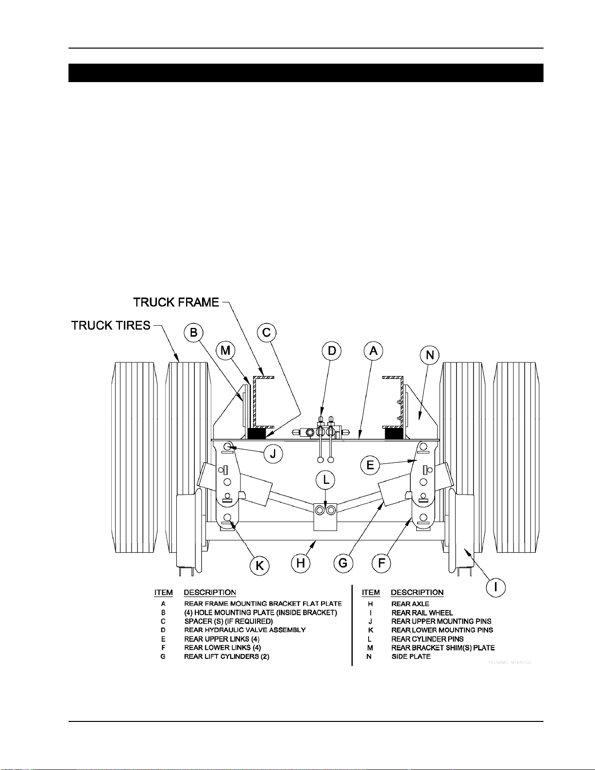
Figure 1.3.1 Rear Railgear Components ...................................... 1-5
Figure 3.2 Railgear Grease Locations ....................................... 3-4
Figure 3.3 Rail Wheel Wear Gauge........................................... 3-6
Figure 4.1.4 Bolt Torque Specifications ....................................... 4-4
Figure 4.2.4 Installation Rails.................................................... 4-6
Figure 4.3.2 Diagram of Key Rear Components............................ 4-8
Figure 4.3.4 Location and Clearance of Rear Railgear.................... 4-9
Figure 4.3.7 Squaring Rear Railgear........................................... 4-11
Figure 4.3.9 Rear Mounting Plate Installation............................... 4-12
Figure 4.3.10 Tack Welding of Rear Spacer ................................... 4-12
Figure 4.5.2 Diagram of Key Front Components ........................... 4-14
Figure 4.5.3 Bolted Joint Cross Section....................................... 4-15
Figure 4.5.4.A Below Frame Rail Bridge Kit..................................... 4-16
Figure 4.5.4.B Between Frame Rail Bridge Kit................................. 4-17
Figure 4.5.5 Front Railgear Mounting Dimensions......................... 4-18
Figure 4.5.7 Front Railgear Clearance......................................... 4-20
Figure 4.6.2 Diagram of Key Cargo Arm Components & Front
Mounting Dimensions ............................................. 4-21
Figure 4.7.1.A Recommended Tack Location for Standard Front
Axle..................................................................... 4-24
Figure 4.7.1.B Recommended Tack Location for Front Stub Axle........ 4-24
Figure 4.7.1.C Front Tire Clearance Above Rail................................ 4-25
Figure 4.8.6 Remote Air Pin-Off Installation – Under Cab............... 4-29
Figure 4.9.3 Behind Cab Installation Height................................. 4-31
Figure 4.10.1 Overall Alignment Procedure and Final Weight
Adjustment........................................................... 4-33
Figure 4.12.A Standard Front Railgear Final Weld-out ..................... 4-34
Figure 4.12.B Front Stub Axle Final Weld-out................................. 4-35
Figure 4.12.C Rear Mounting Plate Weld-off................................... 4-35
Figure 4.12.D Rear Spacer Welding .............................................. 4-36
Figure 5.1.A Rail Sweeps .......................................................... 5-2
Figure 5.1.B Rail Sweep Position................................................ 5-2
Figure 5.2.A Manual Pin-Off....................................................... 5-4
Figure 5.2.B Front Remote Pin-Off.............................................. 5-5
Figure 5.2.C Rear Remote Pin-Off............................................... 5-6
Figure 5.3.1 Cobra Air Brake Location......................................... 5-7
Figure 5.3.2 Front Air Brake Installation...................................... 5-8
Figure 5.3.3 Rear Air Brake Installation ...................................... 5-8
Figure 5.3.5.A Cobra Air Brake Control System Assembly................. 5-10
Figure 5.3.5.B Air Brake Control Kit for Behind Cab ........................ 5-11
Figure 5.3.6 Brake Inspection and Alignment............................... 5-12
Figure 5.3.8 Cobra Air Brake Assembly....................................... 5-13
Figure 5.4 RW-1630/50 Insulated 2-Pc. Wheel Assembly............ 5-15
Figure 5.5 Stub Axle Shunt Wiring........................................... 5-17
Table 3.4.1 Troubleshooting On-Track Problems.......................... 3-7
Table 4.1.5 Manufacturer Equivalent Welding Rod ....................... 4-5
Table 4.3.3 Location of Rear Railgear ........................................ 4-9
Table 4.3.5 Shimming Chart .................................................... 4-10
Table 4.8.1.A Cylindrical Tank Spacing – Under Cab ....................... 4-26
Table 4.8.1.B Squared Tank Spacing – Under Cab.......................... 4-26
This manual suits for next models
1
Table of contents
Other DMF Industrial Equipment manuals