DMF RW-1019 Quick start guide
DIVERSIFIED METAL FABRICATORS, INC.
DMF 665 Pylant Street Atlanta, Georgia 30306
Parts (404) 607-1684 Parts Fax (404) 879-7888 parts@dmfatlanta.com
Service Department (404) 879-7882 service@dmfatlanta.com
Phone (404) 875-1512 Fax (404) 875-4835 info@dmfatlanta.com
http://www.dmfatlanta.com
Parts & Service Manual
RW-1019/1212
Chipper Railgear
May 2020
SERIAL NUMBER (FRONT) ________________________
SERIAL NUMBER (REAR) ________________________
NOTE:
Please refer to the serial numbers when ordering parts or
inquiring about warranty items.

DIVERSIFIED METAL FABRICATORS, INC. CHIPPER RAILGEAR
© 2020 DMF, Inc. All Rights Reserved.
Message from DMF
No matter what your job function is, Operation, Installation, Maintenance, or Repair, it is your
responsibility to familiarize yourself with the entire manual. Once you have read the entire
manual, there are some specific sections that you will want to pay special attention to,
depending on your role.
If you find anything missing, incorrect or unclear in this manual, please contact us. We are
always trying to improve our manuals.
Manuals, service bulletins and general information are available on our website listed below.
We reserve the right to update our manuals without notice. You can download a current manual
at our website (http://www.dmfatlanta.com).
Thank you for choosing DMF Railgear. We make every effort to provide quality, safe and rugged
products for the railroad. We hope you'll find our gear to be satisfactory in every way. We take
product support very seriously, so if you have any questions, please contact us.
Contact:
Diversified Metal Fabricators
665 Pylant St. NE
Atlanta, GA 30306
(404) 875-1512
(404) 875-4835 Fax
(404) 607-1684 Parts
http://www.dmfatlanta.com
info@dmfatlanta.com
Ship to:
668 Drewry St. NE
Atlanta, GA 30306

DIVERSIFIED METAL FABRICATORS, INC. CHIPPER
RAILGEAR
© 2020 DMF, Inc. All Rights Reserved.
TABLE OF CONTENTS
SECTION 1.0 GENERAL INFORMATION
1.1 General Description, Weights & Capacities ...............1-2
1.2 Chipper Railgear ...................................................1-3
SECTION 2.0 OPERATIONS
2.1 Before You Operate the Railgear .............................2-2
2.2 Highway Operation ...............................................2-3
2.3 Getting On the Rail ...............................................2-4
2.4 Getting Off the Rail ...............................................2-6
SECTION 3.0 ROUTINE MAINTENANCE
3.1 Inspection and Maintenance ...................................3-2
3.2 Fluids and Lubrication ...........................................3-4
3.3 Wheel Wear Gauge ...............................................3-5
3.4 Derailment ...........................................................3-7
SECTION 4.0 RAILGEAR INSTALLATION
4.1 Pre-Install ............................................................4-2
4.2 Initial Instructions ................................................4-6
4.3 General Information ..............................................4-7
4.4 Installation of Chipper Railgear ...............................4-8
4.5 Alignment and Rail Test Procedures ........................4-14
SECTION 5.0 RAILGEAR OPTIONS
5.1 Rail Sweeps .........................................................5-2
5.2 Rail Brakes ..........................................................5-6
SECTION 6.0 HYDRAULIC SYSTEM
6.1 General Information ..............................................6-2
6.2 Hydraulic & Electrical Schematics ............................6-6
6.3 Hydraulic and Electrical Component Drawings ..........6-12
SECTION 7.0 REAR RAILGEAR PARTS
7.1 Before Ordering Parts ............................................7-2
7.2 Assembly Drawings ...............................................7-3
7.3 Axle Drawings ......................................................7-6

DIVERSIFIED METAL FABRICATORS, INC. CHIPPER
RAILGEAR
© 2020 DMF, Inc. All Rights Reserved.
LIST OF FIGURES/TABLES
Figure 1.2.1 RW-1019 Chipper Railgear Components ........................1-3
Figure 1.2.2 RW-1212 Chipper Railgear Components ........................1-4
Figure 4.3 RW-1019 Chipper Railgear Major Components ...............4-7
Figure 4.4.1.A Tower Assembly Alignment w/ Axle ..............................4-8
Figure 4.4.1.B Selecting a Common Alignment Reference Point .............4-9
Figure 4.4.1.C Stowed & Deployed Measurements RW-1019 .................4-10
Figure 4.4.1.D Stowed & Deployed Measurements RW-1212 .................4-10
Figure 4.4.1.E Tower Assembly Alignment ..........................................4-11
Figure 4.4.1.F Axle Rod Pin, Axle Lugs & Cylinder Interface ..................4-12
Figure 4.4.1.G Axle Lug Weldment ....................................................4-12
Figure 4.4.1.H Alignment of Second Axle ............................................4-13
Figure 4.5.1 Railgear Alignment Single Axle .....................................4-15
Figure 4.5.2 Railgear Alignment Dual Axles .....................................4-16
Figure 5.2.1 Rail Brake Adjustment ................................................5-6
Table 4.1.6 Manufacturer Equivalent Welding Rod ...........................4-5

DIVERSIFIED METAL FABRICATORS, INC. CHIPPER RAILGEAR
`
© 2020 DMF, Inc. All Rights Reserved. 1-1
SECTION 1.0 GENERAL INFORMATION
1.1 GENERAL DESCRIPTION, WEIGHTS & CAPACITIES ......................................... 1-2
1.1.1 Weights and Capacities .................................................................................... 1-2
1.1.2 Installation ..................................................................................................... 1-2
1.1.3 Options.......................................................................................................... 1-2
1.1.4 Brakes ........................................................................................................... 1-2
1.2 CHIPPER RAILGEAR ....................................................................................... 1-3
1.2.1 RW-1019 Chipper Railgear Components ............................................................. 1-3
1.2.2 RW-1212 Chipper Railgear Components ............................................................. 1-3

DIVERSIFIED METAL FABRICATORS, INC. CHIPPER RAILGEAR
1-2 © 2020 DMF, Inc. All Rights Reserved.
1.1 GENERAL DESCRIPTION, WEIGHTS & CAPACITIES
DMF’s Chipper Railgear is designed for tow behind chippers. The Railgear completely lifts the
chipper tires above rail when deployed. This allows for various tracked chippers to be used on
the same gauge rail.
Two version of the Chipper Railgear are offered. The first version, RW-1019 Chipper Railgear
uses a RW-1019 standard 10” wheel and axle assembly. The gear is actuated by two hydraulic
cylinders per axle. RW-1019 Chipper Railgear is standard for most applications and tailored for
lighter chippers. The second version, RW-1212 Chipper Railgear uses a RW-1212 standard 12”
wheel and axle assembly. This gear uses four hydraulic cylinders per axle. The RW-1212
Chipper Railgear is used only in applications where the chipper is too heavy for standard RW-
1019 Chipper Railgear.
1.1.1 Weights and Capacities
Chipper Railgear Capacity per Railgear Axle @ 20 MPH:
RW-1019 Chipper Railgear: ~8,200 lbs.
RW-1212 Chipper Railgear: ~12,300 lbs.
Chipper Railgear installed weights per axle, no brakes:
RW-1019 Chipper Railgear: ~300 lbs.
RW-1212 Chipper Railgear: ~540 lbs.
1.1.2 Installation
The DMF Chipper Railgear assemblies were designed to minimize the mounting space needed
with minimal modifications to the trailer. The Chipper Railgear is mounted just behind the rear
axle where space is available. The Railgear can be ordered with a second axle, for mounting to
the front of the frame. Spacing should be considered to balance the chipper when the Railgear
is deployed. It should be noted that chippers requiring a second axle must be towed with a
drawbar.
1.1.3 Options
There are multiple options available when ordering a set of Chipper Railgear. The most
commonly ordered options include rail wheel brakes for aided stopping on rail, insulated wheels
to prevent crossing signal actuation and rail sweeps to clear the rail of potentially damaging
materials.
1.1.4 Brakes
NOTE:
Primary braking effort is provided from the towing vehicle when operating on rail. The rail
wheel brake system is intended to assist the vehicle. If the existing vehicle brakes are not
maintained in good working order, the rail wheel brakes are not capable of independently
stopping the vehicle in reasonably short distances.
The optional brakes are hydraulically actuated from the supplied Railgear power unit. When
enabled, the chipper brakes are applied when the brakes are applied in the tow vehicle. A
timer is used to limit the run time of the pump to prevent overuse.
DIVERSIFIED METAL FABRICATORS, INC. CHIPPER RAILGEAR
`
© 2020 DMF, Inc. All Rights Reserved. 1-3
1.2 CHIPPER RAILGEAR
NOTE:
The orientation of brakes can be installed vertically or horizontally to improve brake clearances.
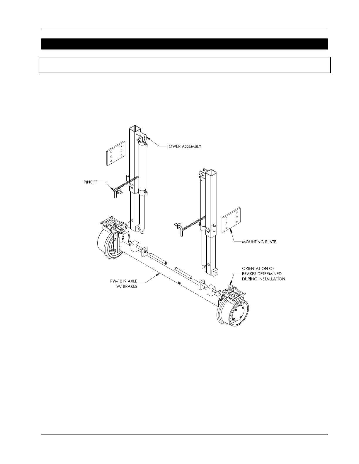
1.2.1 RW-1019 Chipper Railgear Components
Figure 1.2.1 identifies the key components of the RW-1019 Chipper Railgear. Appearances will
vary depending on the selected Railgear options. These item descriptions will be used
throughout this manual.
Figure 1.2.1 RW-1019 Chipper Railgear Components
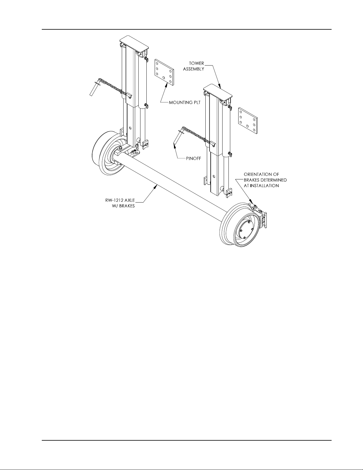
1.2.2 RW-1212 Chipper Railgear Components
Figure 1.2.2 identifies the key components of the RW-1212 Chipper Railgear. Appearances will
vary depending on the selected Railgear options. These item descriptions will be used
throughout this manual.
DIVERSIFIED METAL FABRICATORS, INC. CHIPPER RAILGEAR
1-4 © 2020 DMF, Inc. All Rights Reserved.
Figure 1.2.2 RW-1212 Chipper Railgear Components

DIVERSIFIED METAL FABRICATORS, INC. CHIPPER RAILGEAR
© 2020 DMF, Inc. All Rights Reserved. 2-1
SECTION 2.0 OPERATIONS
2.1 BEFORE YOU OPERATE THE RAILGEAR ........................................................... 2-2
2.1.1 Familiarization of Railgear ................................................................................ 2-2
2.2 HIGHWAY OPERATION ................................................................................... 2-3
2.3 GETTING ON THE RAIL ................................................................................... 2-4
2.3.1 Getting Onto the Tracks ................................................................................... 2-4
2.3.2 Lowering Guide Wheels – Single Axle ................................................................ 2-4
2.3.3 Lowering Guide Wheels – Dual Axles ................................................................. 2-4
2.3.4 On the Tracks ................................................................................................. 2-5
2.4 GETTING OFF THE RAIL .................................................................................. 2-6
2.4.1 Single Axle ..................................................................................................... 2-6
2.4.2 Dual Axles ..................................................................................................... 2-6

DIVERSIFIED METAL FABRICATORS, INC. CHIPPER RAILGEAR
2-2 © 2020 DMF, Inc. All Rights Reserved
2.1 BEFORE YOU OPERATE THE RAILGEAR
2.1.1 Familiarization of Railgear
Clearances & Approach Angles
Installation of Railgear typically reduces ground clearance, with the rail wheels resting below
the frame of the chipper. This must be taken into consideration by the operator when
maneuvering on-road and positioning for Railgear deployment. To avoid equipment and
property damage, operators should be familiar with the modified clearances and working
envelope before towing.
Pin Off Systems and Locations
Walk around the chipper and identify the location and type of Railgear pin off system installed.
Locking valves are provided for each cylinder. Pin Offs are installed on both sides of the
Railgear assembly. It is required that the Pin Offs are used when the Railgear is in both the
highway and rail positions.
Operation Controls
Locate and be familiar with the location of the Railgear operating controls.
Locate the Hydraulic Power Unit, its power source and power switch on the trailer.
If the truck is equipped with Railgear brakes, locate the brake switch. This switch
should only be enabled on rail to avoid continuously running the hydraulic Power Unit.
This manual suits for next models
1
Table of contents
Other DMF Industrial Equipment manuals


