DMM DSN05 Series User manual

DSN05 Series Incremental Encoder Installation Manual
Manual Number : dmmdsn05_inmt | Reference Product Manual : dmmdsnr_pm80
Revision : A1.4
Date : Sept 2013
Encoder Dimension
WARNING
●Depending on application, encoder mounting and tuning procedures may require running of high speed or high
power rotating devices. Ensure all preventative measures with a high level safety control to reduce the risks of user
bodily harm.
●This encoder model is not designed to ensure safety of persons directly or indirectly.
●The interface cable of the DSN encoder is very thin with high density. Do not short the +5VDC supply voltage and
ground terminal. This will permanently damage the encoder.
DMM Technology Corp.
3125 - 21331 Gordon Way
Richmond, BC V6W 1J9
Canada
CAUTION
●The encoder should be mounted in a clean environment. Ensure minimal presence of dust, chemicals or other
hazardous materials. Consult the exact temperature, humidity and protection specification of the encoder model.
●The DSN encoder uses magnetic field sensor measurements for operation. Although the encoder is not very
sensitive to external magnetic disturbances or noise, the mounting and operating environment should have no
presence of excessive magnetic field. Consult DMM Technology Corp. if you suspect problems with this matter.
●Third party safety directive certification documentation available from DMM Technology Corp. upon request. Once
the product is integrated into a higher design or application by the customer, DMM Technology Corp. does not hold
responsibility for conformity to any certification standards.
●Follow all specification requirements of the encoder model and ensure all conditions are satisfied. Improper use of
encoder outside specification outlines can permanently damage encoder and void the warranty. Consult DMM
Technology Corp. if application requires conditions falling outside of encoder model specification.
Installation Manual DMMDSN05_INMT | rev. A1.4 | 09/13
www.dmm-tech.com 01-03

Device Dimension
Mounting Surface
Installation
Step 1. Unboxing
Each DSN encoder packaging should consist of ( 1 ) DSN encoder unit
and ( 1 ) aluminum magnetic rotary unit.
Remove each piece from the packaging. Remove the encoder by vertically
sliding out the main body. Do not remove the encoder by pulling on
the interface cable.
Step 2. Aluminum Magnetic Rotary installation
Apply small amount of surface retaining adhesive to inner bore of rotary
piece.
Recommended adhesive: Loctite 648 or equivalent
Install the rotary piece onto the device shaft with a 0.5mm clearance
between the bottom of the rotary and the device surface/flange.
Tighten the set screw using a M3 hex drive to secure the rotary piece.
Ensure that the 0.5mm clearance is maintained after the set screw is
tightened.
Step 3. Encoder mounting
Consider the output location of the interface cable. Mount the encoder
in the direction with least stress on interface cable.
Apply small amount of thread lock onto device mounting holes.
Recommended thread lock adhesive: Loctite 243 or equivalent
Use an M3 size screw to attach the encoder body onto device. Do not
use washers or spacers between the encoder body and device mounting
surface.
Installation Manual DMMDSN05_INMT | rev. A1.4 | 09/13
www.dmm-tech.com 02-03
Magnetic Rotary

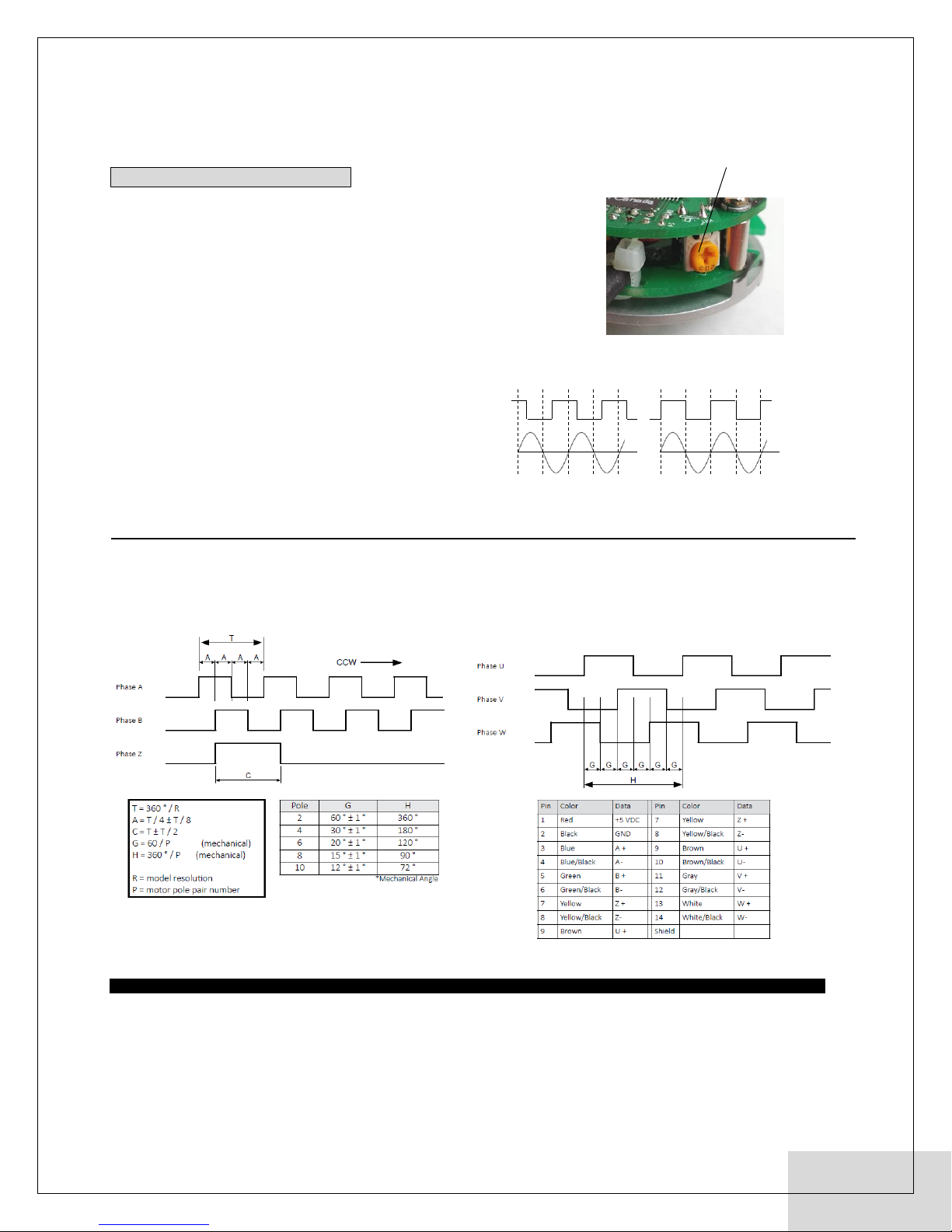
Step 4. Commutation phase adjustment
*This step applicable only to models with commutation output.
For motor applications only.
Power up the encoder with supply voltage.
The commutation phase reference mechanical location is adjusted
using the on-board potentiometer. The mechanical phase angle
can be adjusted up to 180°.
Externally actuate the motor shaft so the motor generates back-EMF,
and the encoder rotary is also rotated. Synchronize the motor back-EMF
voltage with the encoder output U + signal (or V + or W +) by
adjusting the on-board potentiometer.
Rotate the potentiometer while viewing the U + signal and motor
back-EMF voltage to zero synchronize the commutation signal.
Once the motor back-EMF and encoder commutation are matched,
the U,V,W commutation adjustment process is complete.
Ensure the potentiometer dial cannot be unexpectedly moved
during normal operation.
Interface
□A leads B for CCW rotation - viewed from encoder shaft/mounting side
□Line Driver Output
□14-position, 0.4mm O.D. copper conductor
□6mm O.D. interface cable
□Max. Cable Distance = 100m
PRODUCT TERMS
All specified data subject to change without notice to reflect updates and improvements made to product. DMM Technology Corp. warrants the quality and performance of for one year
starting date of shipment from original factory. DMM Technology Corp. assumes no responsibility for damages resulting from user related errors or improper use of product, in which
case the warranty terms will be void. Safety precautions should be considered for all applications. As this product does not include safety conditions, always design a higher level
feedback to reduce the risks of product or bodily harm. All information included in this manual represents data measured under DMM Technology Corp’s own test conditions. Actual
performance may vary and the user is responsible for optimizing the application with respect to the encoder’s capabilities.
DMM Technology Corp. ©2013
Installation Manual DMMDSN05_INMT | rev. A1.4 | 09/13
DMM Technology Corp.
3125 - 21331 Gordon Way
Richmond, BC V6W 1J9
Canada
www.dmm-tech.com 03-03
Potentiometer Adjustment
Mis-aligned
Aligned
Tuning complete!
Encoder U phase
Motor back E.M.F
Measured between U,V
motor power wires