DockStar Smart Thruster User manual

Page 1/ 16
Stern Installation Guide
Introduction
This guide covers the installation of a DockStar Smart Thruster to the stern of a boat. For bow thruster
installations, please see the “Bow Installation Guide”.
There are a number of mounting configurations for installing the Smart Thruster to the stern of a boat.
We will discuss the four most popular configurations in this guide. These configurations are summarized
briefly here:
1. Mount the top and bottom fittings of the T-track assembly directly to the hull of the boat.
2. Mount a stanchion to the aft edge of the swim step and secure the T-track assembly to that
stanchion.
3. Mount the top fitting of the T-track assembly to a horizontal hand-rail and the bottom fitting to
the aft edge of the swim step.
4. Mount the top fitting of the T-track assembly to the hull or gunwale and the bottom fitting to
the aft edge of the swim step.
Some boats have features that will influence which of these configurations is best for a particular boat.
Here are some examples:
A boat with no swim step generally has no interference issues so the top and bottom fittings can
be mounted directly to the hull of the boat.
A boat with a gunwale cap protruding out from the stern may require that a spacer pad be
added to make sure the Smart Thruster does not hit the cap when retracted.
A tender mounted on the swim step may require angling the T-track Assembly to fit between
the tender and the swim step. Mounting the top fitting to the hull or gunwale and the bottom
fitting to the aft edge of the swim step is a good way to accomplish this.
A boat with a swim step located high above the water line will require the T-track assembly to
be mounted rather vertically to make sure the Smart Thruster motors are positioned sufficiently
deep in the water. The stanchion mount or the hand-rail mount work well for mounting the T-
track assembly vertically. Ideally, the motors should be at least 8 inches below the surface of
the water when deployed.
Care should be taken to avoid the main engine’s exhaust from hitting the T-track assembly or
any part of the Smart Thruster.
Some sail boats with “sugar scoop” sterns may require creativity in order to mount the Smart
Thruster to the stern. Often, it is advisable to add a stanchion or additional railing to provide an
adequate mounting point for the upper part of the T-track assembly.
The thruster does not need to be installed on the center line of the boat. In fact, it typically is not for a
stern installation. The thrusters should be mounted inboard enough to make sure that neither prop
extends out past the side of the boat, with some extra clearance to avoid hitting the props on the dock
when not parallel to the dock. If possible, it is best to position the Smart Thruster so it is not in line with

Page 2/ 16
the main engine(s) thrust. For single engine boats this means mounting the Smart Thruster off the
center line. For twin engine boats, this means mounting the Smart Thruster closer to the center line.
The boat owner must determine whether there is adequate clearance from all objects to be able to
mount the Smart Thruster to the stern of their boat.
Getting Started
The Smart Thruster is mounted to the stern of your boat by first mounting a stainless tube and T-track
assembly to your stern and then sliding the Smart Thruster up and down on this T-track. The T-track
assembly is mounted in one of the four configurations described below. Each configuration is described
in its own section of this document.
Configuration 1: Top and bottom mounted directly to hull
For this configuration, the top and bottom deck
hinges are mounted using the 10-32 flat-head
through-bolts provided. The bottom fixture should be
located as low on the stern as possible, but should be
no less than about 4 inches from the center of the
hinge to the water line.
The flat-head screws should be secured with the
fender washers and nylock nuts provided. 3” flat
head screws are provided. These may be too long for
your installation. These may either be cut to the
proper length or proper length stainless steel 10-32
screws can be purchase from your local marine or hardware store.
It is a good idea to use a good marine sealant under the fittings when doing the final installation.
The “Stern Hull-Mount Installation Kit” is shown in the picture below:

Page 3/ 16
The top of the T-track assembly is on the right. The top fitting is standard deck hinge that mounts with
two 10-32 flat-head screws. The bottom fitting is a swivel hinge that also mounts with two 10-32 flat
head screws. There is a rubber spacer that fits underneath the swivel part of this hinge. Be careful not
to drop this spacer into the water when installing the hinge! It is required for this hinge to function
properly.
The length of the T-track is 22”. The length of the stainless tube is 25”. The overall length with top and
bottom hinges attached is 29.5”. DockStar can provide a shorter track and tube on request for smaller
sterns.
There are two cleats mounted on the sides of the T-track assembly at the top. These are used to secure
the lanyard. Installation of the lanyard will be discussed at the end of this guide.
The block and sling in the upper left of the picture above are used to attach the lanyard to the thruster.
How this is done is discussed at the end of this document. The four 10-32 screws, fender washers, and
nylock nuts for mounting the two hinge fittings are shown in the upper center of the picture above. The
lanyard is shown in the upper right.
The T-track is positioned on the stainless tube such that the Smart Thruster will be held parallel to the
mounting surface of the T-track assembly. If the stern is curved, the thruster will be parallel to the
tangent of the curved stern at the point of mounting. This may mean that the thruster is not
perpendicular to the keel of the boat. This is typical and does not present a performance issue.
That’s it. Four screws installed into the stern and you’re done except for the lanyard which is described
at the end of this document.
Thruster Deployed Thruster Retracted
In Sand Piper’s installation it was necessary to place a spacer block made out of Starboard plastic to
provide clearance past the gunwale trim. The spacer block is visible (if you look closely) in the pictures
above.

Page 4/ 16
The picture on the right shows another hull mounted
installation. In this case, a slat was removed from the
swim step to allow the thruster to slide up and down
through the swim step opening. This solution
provides for vertical mount to achieve good motor
depth and avoids interfering with the tender and
other usage of the swim step.
Configuration 2: Stanchion Mount
The “Stanchion Mount Installation Kit” is shown above. This kit includes a T-track assembly mounted to
a stanchion that is ready to be mounted to the aft edge of the swim step. This kit also includes a block
and sling (upper left), four sets of mounting hardware (upper center), and a lanyard (upper right).

Page 5/ 16
The stanchion is 32” long. The T-track is 22” long, and
the stainless tube for the track is 25” long.
To mount this T-track assembly configuration it is only
necessary to drill the four holes for the stanchion base
and to secure it with the four screws, fender washers,
and nylock nuts. It is a good practice to seal the
bottom of the stanchion with a good marine sealant.
The stanchion base must be placed close enough to
the edge of the swim step to allow clearance for the
thruster to slide down the T-track. Care should be
taken to align the rotation of the stanchion base such
that the face of the T-track is parallel to the aft edge of
the swim step. This will ensure that the thruster
motors run parallel to the aft edge of the swim step.
For some swim steps it may be necessary to add a
stanchion brace to this stanchion to minimize the
flexing caused by the torque exerted by the thruster
onto the base and thus onto the swim step
immediately around the base.
It may also be necessary to use a backing plate on the
bottom of the swim step to spread the load out. It all
depends on the nature of the swim step.
Even with a solid swim step, there will be noticeable
flexing of the stanchion tube. The use of a stanchion
brace will virtually eliminate this.
The following images show the stanchion mount configuration installed.

Page 6/ 16
Notice how close the stanchion base is mounted to the aft edge of the swim step to allow the Smart
Thruster to clear the swim step when deployed and retracted.
Configuration 3: Hand-rail Mount
This configuration has the added advantage of
providing a hand rail for safety and convenience. This
owner uses the hand rail to enter and leave his
tender. The T-track assembly mounts to the
horizontal section of the handrail at the top and to
the aft edge of the swim step at the bottom.

Page 7/ 16
The “Hand-rail Mount Installation Kit”configuration of T-track assembly is shown above. The top of the
assembly is on the right. A hinged top-slide secures the top of the assembly to the horizontal hand rail.
A swivel hinge is used to secure the bottom of the assembly close to the aft edge of the swim step.
There is a rubber spacer that fits underneath the swivel part of this hinge. Be careful not to drop this
spacer into the water when installing the hinge! It is required for this hinge to function properly.

Page 8/ 16
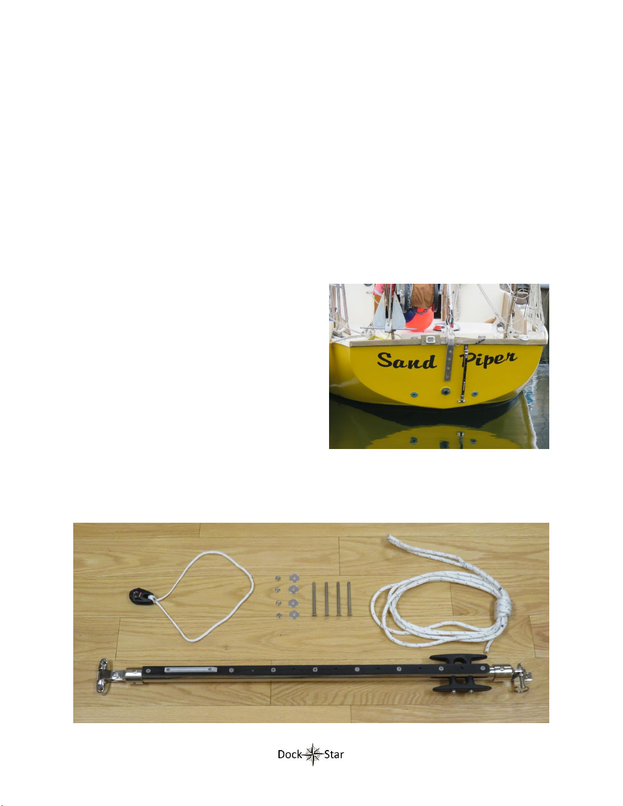
The T-track is 22” long, the stainless tube is 48” long, and the over-all length is 53.5”. This is
intentionally over-sized to allow the stainless tube to be cut to length to fit the particular rail of your
boat.
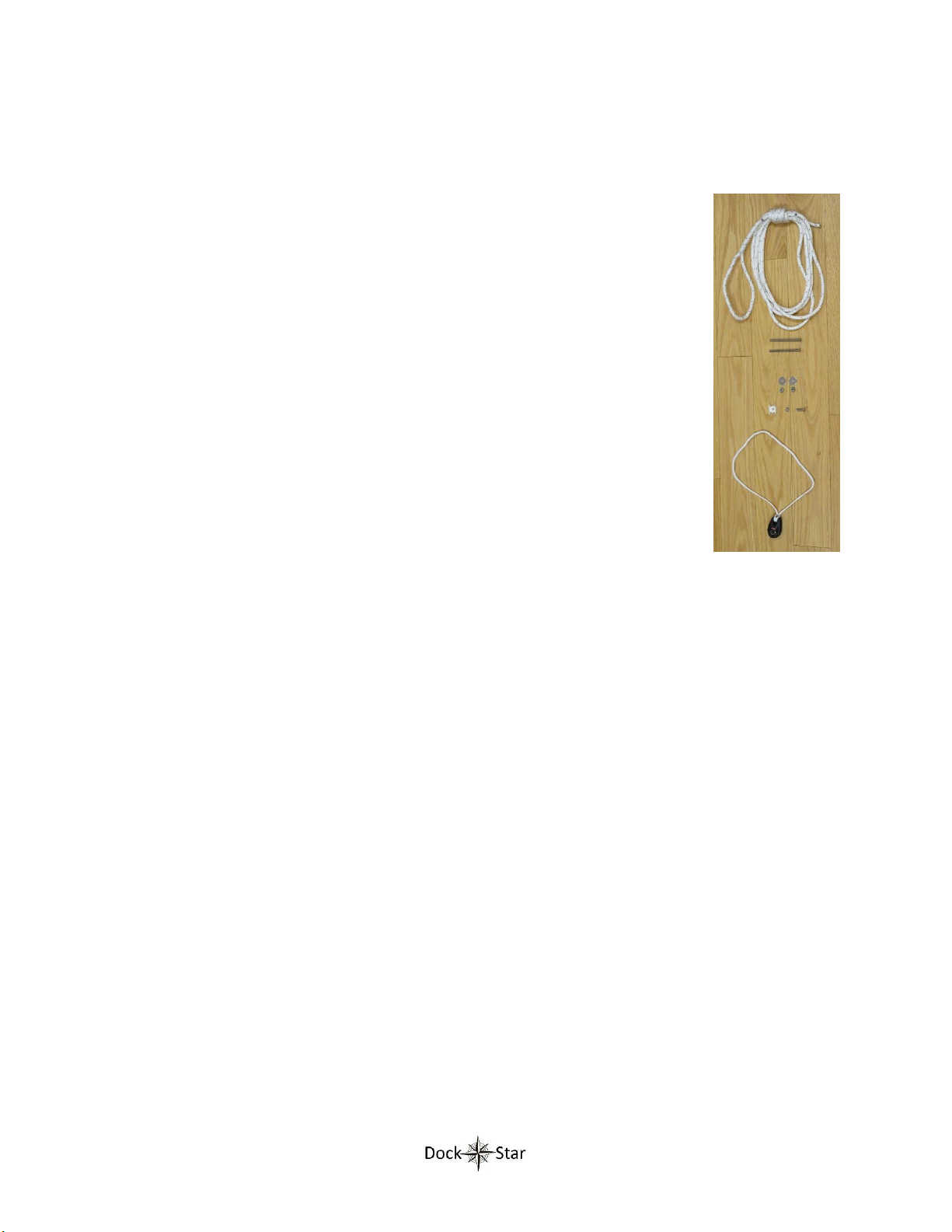
The other elements of the kit are shown to the right. The lanyard is shown at the
top. Two sets of flat-head screws, fender washers, and nylock nuts are shown in the
middle. These are used to secure the swivel hinge to the swim step. No hardware is
required to secure the stainless tube to the handrail since this is done by the
clamping action of the hinged top-slide. At the bottom of the pictures is the block
and sling used to attach the lanyard to the Smart Thruster. How this is attached is
shown later in this document.
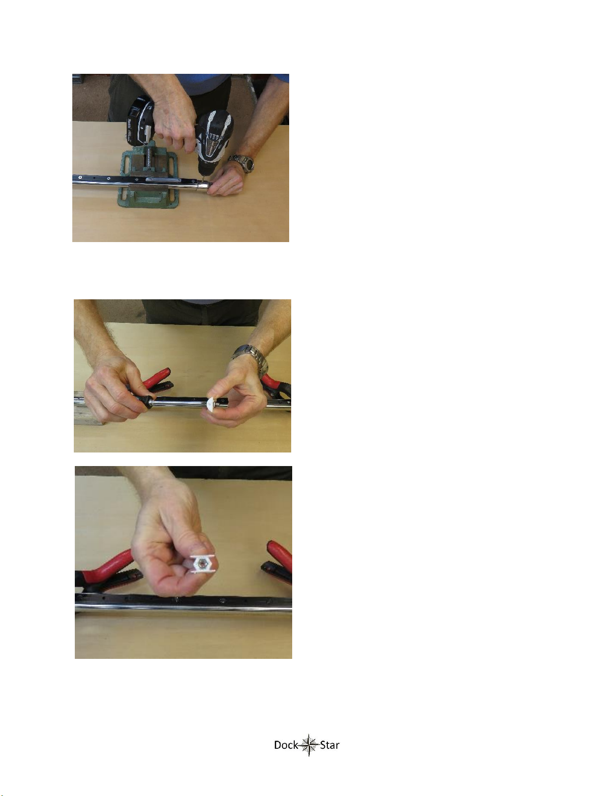
Also included is a plastic nut holder, 10-32 nut, and 10-32 pan-head screw (shown
right above the sling). These are used to secure the top end-cap to the stainless
tube once the stainless tube is cut and properly oriented in the end-cap.
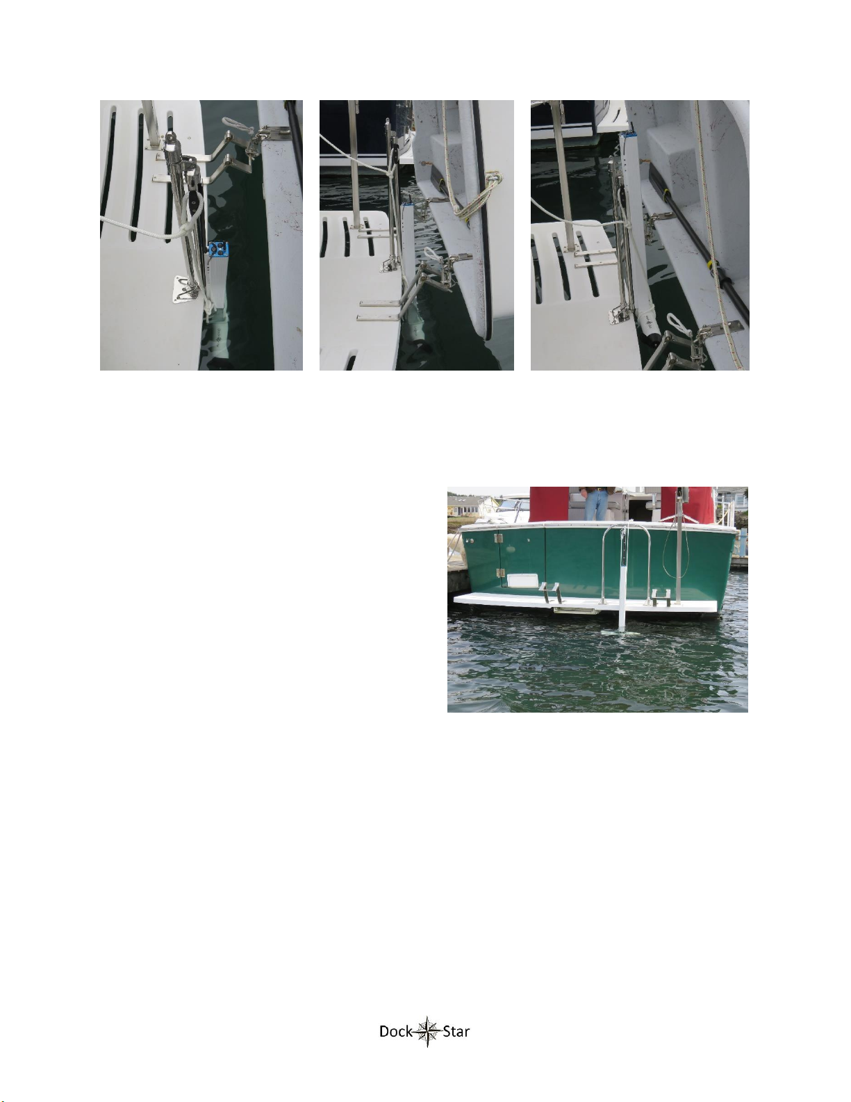
Since various hand-rails are at different heights, it is necessary to cut the stainless
tube to fit the height of the boat’s particular hand rail. The bottom swivel hinge
should be mounted to the swim step (with the hinge’s included rubber spacer in
place) in the appropriate position. Care should be taken to align the rotation of the
lower swivel hinge such that the face of the T-track is parallel to the aft edge of the
swim step. This will ensure that the thruster motors run parallel to the aft edge of the swim step.
It is best to not remove the bottom end-cap from the stainless tube. To separate the stainless tube from
the bottom swivel hinge for mounting the swivel hinge, unscrew the hinge screw holding the end-cap to
the swivel hinge.
The top hinged top-slide should be clamped to the handrail and aligned to the bottom hinge. The top
and bottom hinge fittings should be placed so that the stainless tube when mounted is perpendicular to
the aft edge of the swim step at the point of the lower hinge fitting.
It is now time to determine the proper length to cut the stainless tube. With the stainless tube still
secured into the bottom end-cap reattach the bottom end-cap to the swivel hinge. With the stainless
tube not inside the top end-cap, the tube can be placed alongside the top end-cap to measure where to
cut the excess tubing (from the top). Measure this length and record it for comparison to the next
measurement.
As a check, perform a second measurement to determine the distance between the inside bottoms of
the two end-caps. The internal dimension of each end cap is nominally about 1.2 inches. Thus the
length of the stainless tube is equal to the distance between the rims of the two end-caps plus 2.4”. Be
sure to make this measurement very carefully. This measurement should give you the same length
result as the first measurement. If not, recheck. Also, make sure the two hinge fittings are properly
located so as to allow clearance for the Smart thruster to come off the rail at the top of the T-track and
to slide clear of the edge of the swim step and any obstacles at the aft of the boat. Remember, once
you cut the stainless tube it cannot be lengthened.

Page 9/ 16
The picture below shows the distance between the two end-cap rims and the length of the stainless
tube (including the section inside the end-caps). The difference between these two lengths is nominally
2.4 inches. This is useful to know since it is easier to measure the end-cap rim to rim distance.
Once cut, the top end cap must be secured to the stainless tube. The following steps outline how this is
done.
Step 1: Attach the bottom end-cap to the bottom swivel hinge (which is no mounted to the swim step).
The stainless tube should still be secured inside the bottom end-cap.
Step 2: Loosely clamp the hinged top-slide to the hand rail with the top end-cap not attached to the
hinged top slide.
Step 3: Slide the top end-cap onto the stainless tube with the set screw on the opposite side of the T-
track. Leave the set screw loose for now.
Step 4: Attach the top end-cap to the hinged top-slide.
Step 5: Tighten the hinged top-slide screw to securely clamp the top-slide to the hand rail.
Step 6: Make sure the T-track is square to the aft edge of the swim step and tighten the top end-cap set
screw. Now is a good time to verify that the thruster slides up and down the T-track without
interference.
Step 7: Disconnect the T-track assembly with the end-caps still attached (disconnect the two end-caps
from their fittings).
Step 8: Drill a 3/16” hole into the top end-cap aligned with the center of the T-track as follows:
End-cap rim to rim distance
Stainless tube length

Page 10/ 16
With the set screws still holding the top end-cap in
the correct position, drill a 3/16” inch hole about
7/16” from the rim of the top end-cap. This hole must
be directly in line with the 10-32 flat-head screws
holding the T-track. Drill this hole carefully because if
it is not well aligned the pan-head screw will interfere
with the Smart Thruster sliding along the track. The
end-cap is cast 316 stainless steel with a thickness of
about 1/8”. It is difficult to keep the drill bit from
“walking” when drilling by hand. It is recommend that
this step is done using a drill press to insure proper
alignment.
Step 9: Insert the 10-32 nut into the nut holder:
Use a screw to pull the 10-32 nut into the nut holder.
The nut should be held securely by the nut holder.

Page 11/ 16
Step 10:Secure the top end-cap to the stainless tube:
Remove the top end-cap from the tube.
Insert the end-cap nut holder (with nut) into the
tube lined up with the hole just drilled.
The nut holder should be oriented so that its
convex surface is on the side closest to the newly
drilled hole.
Slide the top end-cap onto the stainless tube, but
do not tighten the set screw.
Align the new hole in the top end-cap to the new
hole in the stainless tube.
Apply thread lock to the 10-32 pan-head screw.
Insert and tighten a 10-32 pan-head screw into
the top end-cap.
Remove the set screws from the end-cap. It is no
longer needed.
The purpose of the pan-head screws holding
the end-caps on is to keep the stainless tube
from rotating relative to the end-caps (and
thus the boat). Also, the two pan-head
screws push the end-caps away from the T-
track. This is necessary to provide enough
clearance for the track guide on the Smart
Thruster to clear the end-caps.
Gap Between end-
cap and rail
No Gap

Page 12/ 16
Refer to the sketch to the right. The
outer diameter of the stainless rail is
smaller than the inner diameter of the
end-cap. The pan-head screw (not
shown) pulls the rail inside the end-
cap tightly to the side nearest the T-
track providing sufficient clearance
between the thruster shaft and the
end-cap.
Unfortunately, the manufacturers of
the end-caps do not tightly control the thickness of the end-cap walls. If the walls are too thick, there
will be insufficient clearance. If this is encountered the problem can be resolved by grinding away the
inside of the end-cap on the side of the T-track to thin the walls and provide the required clearance.
Configuration 4: Hull to swim step mount
This configuration is handy when having to squeeze
the Smart Thruster between the swim step and a
closely mounted tender as shown to the right. This
configuration is not applicable for wide swim steps.
In those cases, a hand rail or stanchion should be
mounted closer to the swim step edge. A wide swim
step requires the Smart Thruster to be angled too
shallow and thus not get deep enough into the water.
The top of the T-track assembly is secured to the hull up by the gunwale with a standard deck hinge as
shown in the photos above. For this particular boat, to allow clearance for the Smart Thruster to slide
past the wood gunwale rail a white plastic spacer is used under the top fitting. A swivel hinge is used to
secure the bottom of the T-track assembly to the aft edge of the swim step. This must be close enough
to the aft edge to allow clearance between the Smart Thruster and the swim step. There is a rubber
End-Cap
Rail
T-Track
Thruster Shaft
Tight Clearance

Page 13/ 16
spacer that fits underneath the swivel part of this hinge. Be careful not to drop this spacer into the
water when installing the hinge! It is required for this hinge to function properly.
The “Angled Stern Mount Installation Kit”shown above. The top of the assembly is on the right with
the standard deck hinge. The bottom with the swivel hinge is on the left. The lanyard is on the upper
right. The block and sling that secure the lanyard to the Smart thruster are shown on the upper left. To
the left of the lanyard are the four sets of 10-32 flat head screws, fender washers, and nylock nuts used
to bolt the two hinge fittings to the boat.
Since the stainless tube needs to be cut to length, the top end-cap is not secured to the stainless tube
with a pan-head screw. This must be done after the tube is cut to fit the particular boat. A plastic nut
holder, 10-32 pan-head screw, and 10-32 nut are shown to the right of the block and sling, and are used
for securing the stainless tube to the upper end-cap once the tube has been cut.
The T-track is 22” long, the stainless tube is 48” long, and the over-all length is 52.5”. This is
intentionally over-sized to allow the stainless tube to be cut to length to fit your particular boat.
The boat owner must determine the proper length to cut the stainless tube. One way to do this is to
mount the two hinge fittings in their proper locations. It is best to mount the upper hinge with only one
screw and one drill hole at this point. This will allow for rotating the hinge to obtain proper alignment
with the lower hinge. Once the alignment step is completed, the second screw can be added. The two
hinge fittings should be placed so that the stainless tube when mounted is perpendicular to the aft edge
of the swim step at the point of the lower hinge fitting.
The lower end-cap is already secured to the stainless tube. The lower fitting must be positioned to be
parallel to the aft edge of the swim step at the point that it is to be mounted. It may be helpful to
disconnect the bottom end-cap from the bottom swivel hinge to make it easier to mount the bottom
swivel hinge to the swim step. Similarly, it may be helpful to remove the top end-cap from the top
hinge.
Once the two fittings are mounted (with only one hole and screw at this point for the upper fitting), It is
time to determine the proper length to cut the stainless tube. With the stainless tube still secured into
the bottom end-cap reattach the bottom end-cap to the swivel hinge. With the stainless tube not inside
the top end-cap, reattach the top end-cap to the top hinge. The stainless tube can be placed alongside
the top end-cap to measure where to cut the excess tubing (from the top). Measure this length and
record it for comparison to the next measurement.

Page 14/ 16
As a check, perform a second measurement to determine the distance between the inside bottoms of
the two end-caps. The internal dimension of each end cap is nominally about 1.2 inches. Thus the
length of the stainless tube is equal to the distance between the rims of the two end-caps plus 2.4”. Be
sure to make this measurement very carefully. This measurement should give you the same length
result as the first measurement. If not, recheck. Also, make sure the two hinge fittings are properly
located so as to allow clearance for the Smart thruster to come off the rail at the top of the T-track and
to slide clear of the edge of the swim step and any obstacles at the aft of the boat. Remember, once
you cut the stainless tube it cannot be lengthened.
Once cut, the top end-cap must be secured to the stainless tube. The following steps outline how this is
done.
Step 1: Attach the bottom end-cap to the bottom swivel hinge. The stainless tube should still be
secured inside the bottom end-cap.
Step 2: Slide the top end-cap onto the stainless tube with the set screw on the opposite side of the T-
track. Leave the set screw loose.
Step 3: Attach the top end-cap to the upper hinge. Rotate the upper hinge (that is still only secured with
one screw) to be well aligned with the T-track assembly.
Step 4: Drill the second hole for the upper hinge and install the flat-head screw, washer, and nut. It is a
good idea to seal the bottom of the hinge with a good marine sealant prior to final tightening of the two
screws. After applying the sealant, fully tighten the two hinge screws.
Step 5: Make sure the T-track is square to the aft edge of the swim step and tighten the top end-cap set
screw. Now is a good time to verify that the thruster slides up and down the T-track without
interference.
Step 6: Disconnect the T-track assembly with the end-caps still attached (disconnect the two end-caps
from their fittings).
Final 3 Steps: Follow steps 8, 9 and 10 outlined for the handrail configuration above for securing the top
end cap to the stainless tube
The Hull-to-swim-step thruster configuration Looking under the tender at the
deployed retracted thruster

Page 15/ 16
Lanyard Attachment
The lanyard attachment for all four mounting
configurations is the same. The block and sling is
attached to the thruster motors as shown in the
picture on the right. To do this, slide the sling over
the top of the Smart Thruster’s shaft. Grab the block
and wrap it around the motors going toward the T-
track guide first and around to the other side of the
motors. Tuck the block under the sling along the
shaft. The sling is attached to the block
asymmetrically. The block should be positioned on
the thruster with the loop from the sling closest to the
thruster shaft.
The fixed end of the lanyard is attached to a hard
point such as a cleat or pad-eye, then run through the
block, and then up to another hard point (usually a
cleat). The two cleats on the upper end of the T-track
assembly are available to serve as both hard points.
The lanyard fixed end can be attached to one cleat.
To do this, feed the spliced eye through the center of
the cleat from the side opposite the T-track and wrap
the loop around the cleat as shown to the right. Pull
the loop tight to secure.
Now run the loose end of the lanyard through the
block and back up to the cleat on the other side.
To lower the thruster, simply pay out the loose end of
the lanyard until the thruster rests on the track stop.
Then secure the lanyard to the cleat. To raise the
thruster, un-cleat the line and pull until the thruster is
at the desired height and secure the lanyard to the
cleat.
The two pictures to the right show the thruster
retracted (on the left) and deployed (on the right)
Alternatively, cleats or other attachment points can
be used on the gunwale, hull, or a railing.

Page 16/ 16
Dimensional drawings of the Smart Thruster are provided below for your reference.
Other manuals for Smart Thruster
1
Other DockStar Boating Equipment manuals
Popular Boating Equipment manuals by other brands

Craftsman
Craftsman CMXGZBF7124571 instruction manual

Classic Accessories
Classic Accessories StormPro Instructions & Care

POWERWINCH
POWERWINCH Model 915 owner's manual

Ultraflex
Ultraflex A97 Installation and maintenance manual

Harken
Harken T2701B instructions

DAVIS
DAVIS Wheel-a-Weigh 1482 Standart instruction manual