1. GENERAL INSTRUCTIONS
Dear Customer, Congratulations on the purchase of this pro-
duct. The garage door drive has been developed using the
latest state-of-the-art technology and is manufactured by
using the most reliable and modern electrical / electronic
components.
The manufacturer reserves the right to make improvements
or modications to the devices and the assembly and ope-
rator manuals at any time without prior notication to this ef-
fect.
Please spare a few minutes of your precious time before in-
stalling
the equipment and putting it into operation. Please read the
following notes and instructions carefully.
The manufacturer disclaims any responsibility for loss and
damage to property or human injury resulting from improper
installation, commissioning, operation or service and repair
to the garage door, accessories and the drive.
A garage door drive represents an incomplete ma-
chine in the context of the Machinery Directive,
2006/42/EC, and the machine is formed using the
combination of the door and drive based on the
conformity evaluation procedure to be carried out
possibly by the manufacturer: the system may only
be commissioned by qualied technicians. The EC
manufacturer's declaration and the CE mark form
part of the commissioning.
It is prohibited to operate the system if the EC
manufacturer's declaration and the CE mark have
not been provided.
1.1 Allgemeine Sicherheitshinweise
IMPORTANT SAFETY INSTRUCTIONS: ATTENTION! IT IS
IMPORTANT FOR SAFEGUARDING HUMAN LIVES TO
COMPLY WITH ALL INSTRUCTIONS!
THIS MANUAL MUST BE PRESERVED UNDER ALL CIR-
CUMSTANCES! Please ensure that all those who are
entrusted with the operation, maintenance and re-
pair of the system have access to this documentati-
on.
This garage drive door may only be assembled, wi-
red and connected, and commissioned by
qualied technicians. In particular, knowledge and
experience is required in the following areas:
- general and special safety rules and regulations
and accident prevention provisions,
- use of safety equipment and devices,
- EN 13241-1 (Garage door product standard)
- EN 12635 (Installation and operation requirements)
- EN 12453 (Safety issues when using power-opera
ted doors and roller shutters)
- 2006/42/EC (Machinery Directive)
Electrical installations (230V) at site may only be
carried out by skilled electrical technicians.
The safety rules and regulations applicable for ac-
cident prevention must be complied with during in-
stallation.
The garage drive door may only be installed on a
properly functioning garage door that is balanced
with respect to its weight.
IMPORTANT SAFETY INSTRUCTIONS FOR PREVEN-
TING PERSONAL INJURIES AND DAMAGE TO PRO-
PERTY!
IMPORTANT INSTRUCTIONS FOR PROPER INSTAL-
LATION AND OPERATION!
CONTENTS
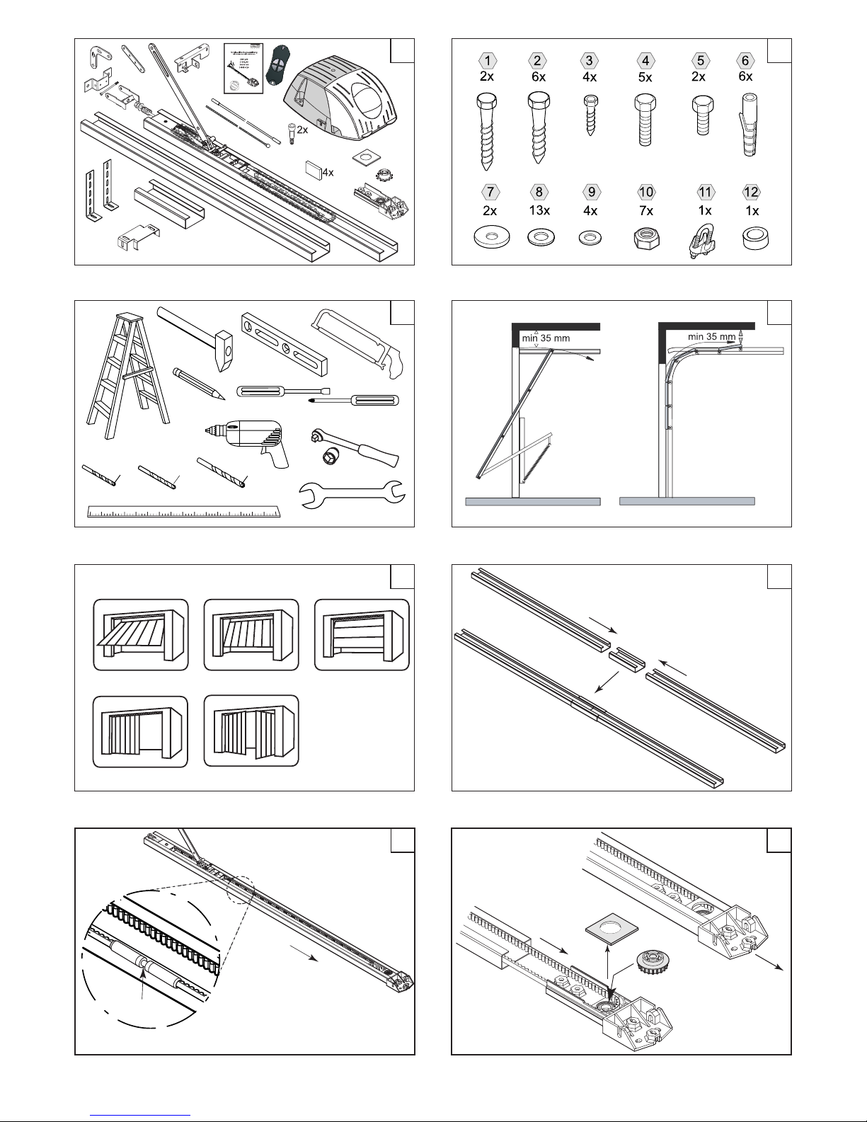
Assembly drawings 2
Overview diagram 6
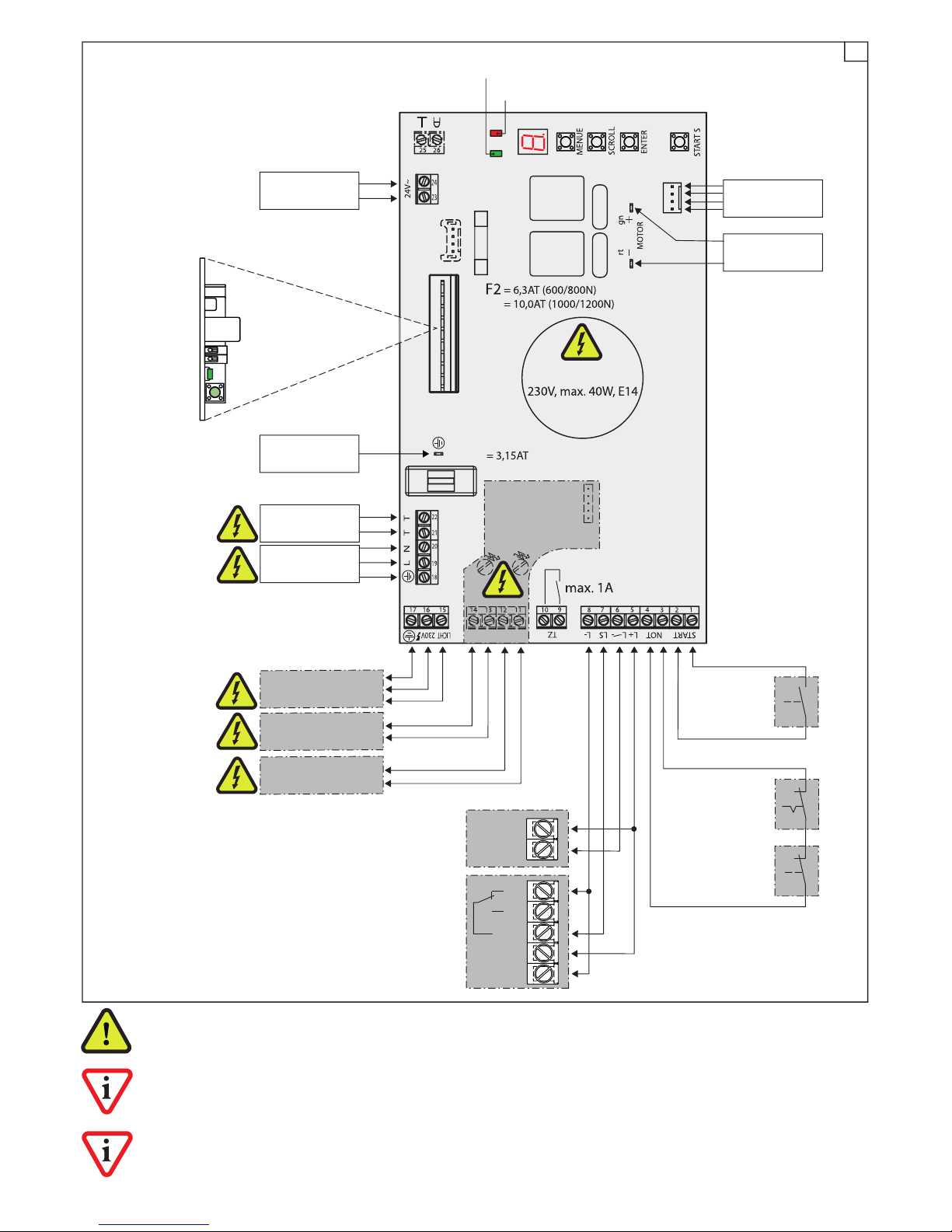
Controller connection diagram 7
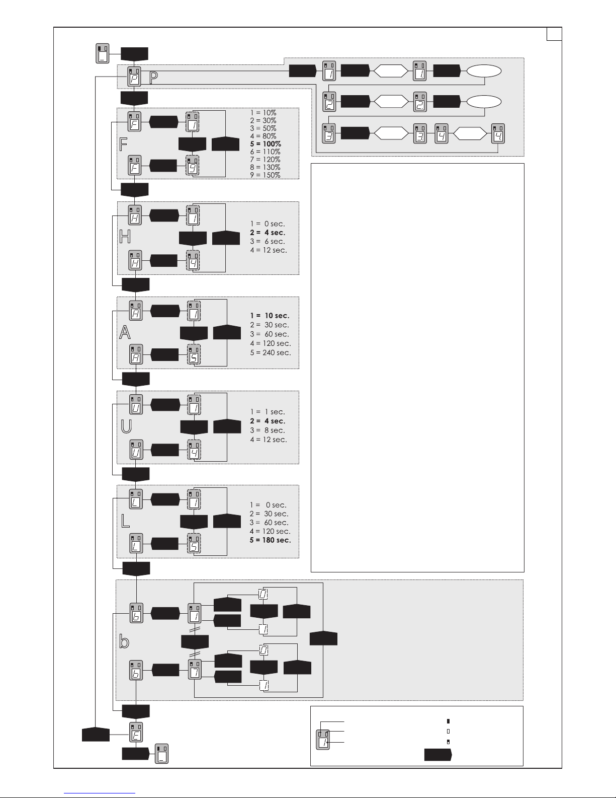
Brief instructions on programming 8
1.0 GENERAL INSTRUCTIONS 9
1.1 General notes on safety 9
1.2 Storage and transport 10
1.3 The garage door drive 10
1.4 Scope of supply 10
1.5 Proper use 10
1.6 Prerequisites for installation 10
2.0 ASSEMBLY 10
2.1 Preparatory work 10
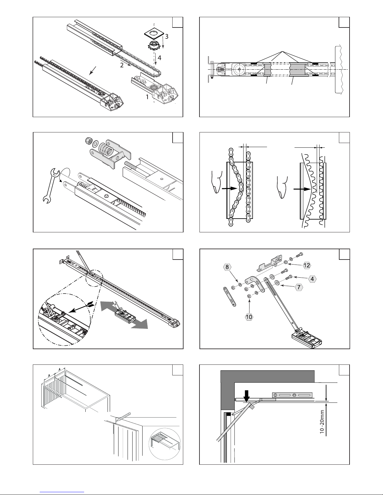
2.2 Pre-assembly of the drive 11
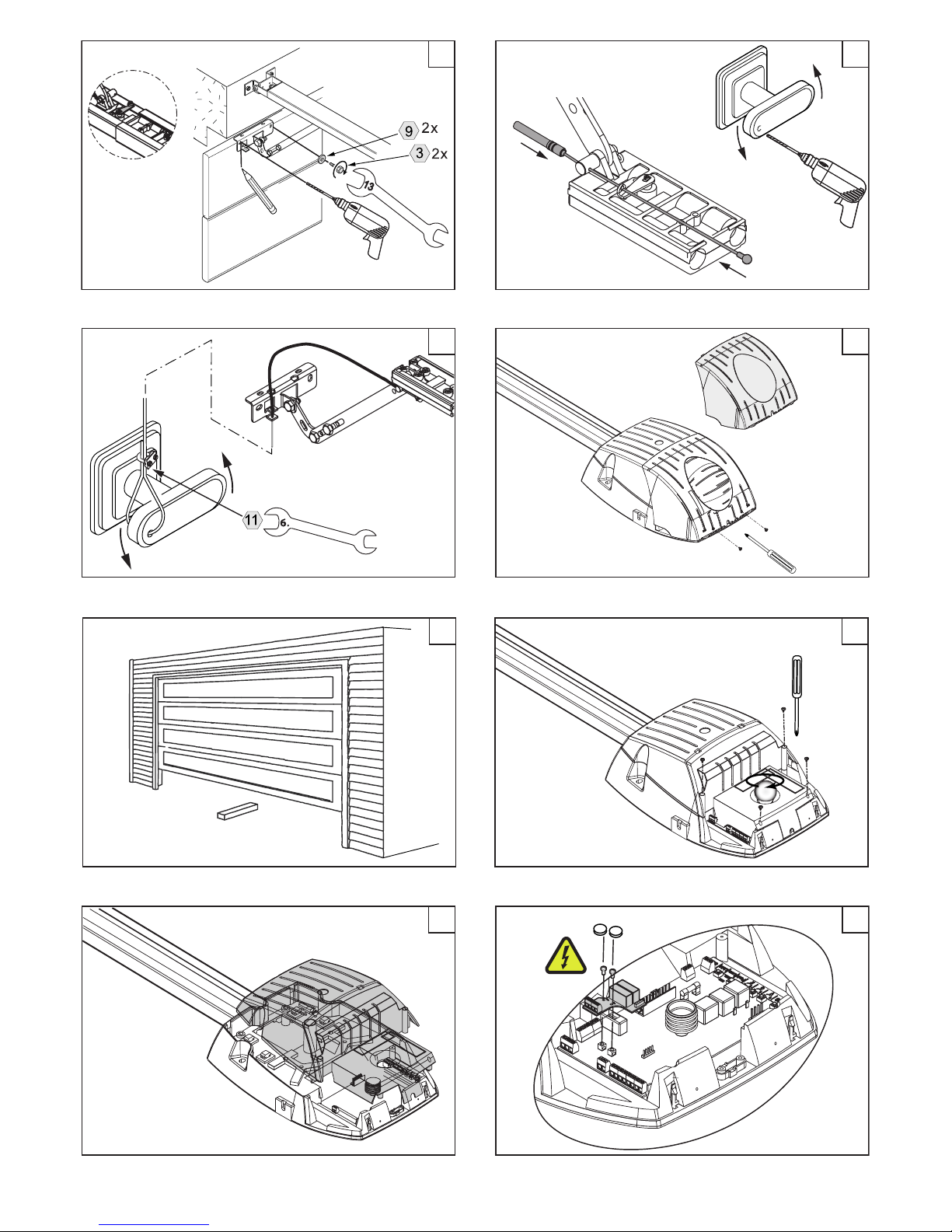
2.3 Installing the drive 11
2.4 Afxing warning labels 12
2.5 Manual functional test /
Emergency unlocking 12
3.0 COMMISSIONING 13
3.1 Menu control 13
3.2 Programming path and force 13
3.3 Adjusting the shutdown force 14
3.4 Testing the hindrance detection system 14
3.5 Add-on functions in the menu 14
3.6 Wireless 16
3.7 Teaching the handheld transmitter
(plug-in receiver) 16
3.8 Deleting the handheld transmitter
(plug-in receiver) 16
3.9 Declaration of conformity 16
3.10 Handing over and user training 16
4.0 CONNECTING ACCESSORIES 17
4.1 Push-buttons 17
4.2 Light barrier 17
4.3 Safety switch strip 17
4.4 Antenna (plug-in receiver) 17
4.5 Signal module 18
4.6 Warning lamp / Door status indication 18
4.7 External lighting 18
4.8 Emergency off / ap door contact 19
4.9 Centre suspension 19
5.0 OPERATING THE SYSTEM 19
5.1 Instructions for safe operation 19
5.2 Operation 20
5.3 Fault indications 20
5.4 Rectifying faults 21
5.5 Maintenance and repair 22
6.0 DISPOSAL 22
7.0 TECHNICAL SPECIFICATIONS 22
8.0 ACCESSORIES 23
EC Explanation of installation
DOCOMATIC 9/23 04-10