A-191 MCV 16 System A - 100 doepfer
8
4.4 User examples
Modulation-rich synthesizer patch
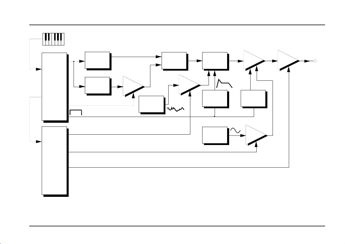
The example in Fig. 2 shows a ‘classic’ synthesizer
patch: 2 VCOs, VCF (A-122) and VCA (A-130). Modu-
les A-190 and A-191 act as the link to a MIDI key-
board, and are set to the same MIDI channel. The
THRU from the A-190 is connected to the MIDI IN of
the A-191.
This patch gives a vast range of modulation possi-
bilities accessible from velocity, mod wheel, pedals,
and aftertouch:
• VCO 2 level
VCO 2’s amplitude level (ie. volume) can be con-
trolled with a pedal. In this example, the A-190’s
second CV output (CV 2) has been previously
programmed to respond to MIDI controller #04, but
CV output C4 on the A-191 could have equally
well been used.
• Modulation of VCF resonance
Filter resonance is modulated by a random vol-
tage source (the A-118’s random output). The
intensity of this modulation is controlled by the
modulation wheel (output C1 on the A-191).
• Amplitude modulation
The intensity of the amplitude modulation created
by the LFO patched into the VCA (A-130) is control-
led by aftertouch (output AT on the A-191).
• Overall volume
The overall volume of the output signal sent to the
monitoring system is controlled by MIDI controller #7
(Volume) (output C7 on the A-191). This controller can
be assigned to a pedal, pitch ribbon, etc. on your
master keyboard.
H If you want to use a MIDI controller which the
A-191 doesn’t support - for instance a
sustain pedal - then you can always set the
A-190 to respond to it, and output it from its
CV2 socket.
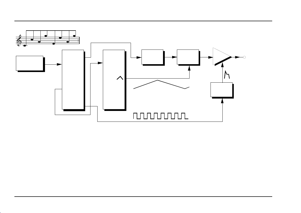
MIDI-synchronised LFO
The internal LFO on the A-191 is synchronised to MIDI
clock. This is particularly useful when you’re using a
MIDI sequencer or arpeggiator with the A-100.
An example is shown in Fig. 3. In this patch, the
internal LFO modulates the VCF’s cut-off frequency.