2 3931219/04/08/D
Doepke
Bedienungsanleitung
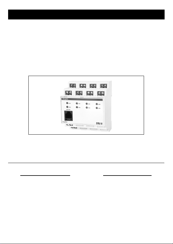
Dupline Signalumsetzer DSU 8
1. Allgemeines
Der Signalumsetzer DSU 8 ist eine Komponente des Dupline Installationssystems und
ermöglicht die Umsetzung von bis zu acht Spannungssignalen zur Übertragung auf
dem Dupline-Bus.
Die Eingänge sind für Gleichspannungen von 20 V bis 300 V oder Wechselspannungen
von 20 V bis 250 V bei 50 Hz geeignet; auf Polarität muss nicht geachtet werden. Zu-
dem ist ein gemischter Betrieb zulässig.
Bei fachgerechter Montage und Nutzung einer Spannungsart für alle Kanäle erfüllt der
DSU 8 die Bestimmungen für Schutzkleinspannung zwischen Netz- und Steuerseite.
Die in der frontseitigen Modularbuchse angebrachte, grüne LED zeigt die ordnungsge-
mäße Arbeitsweise des Dupline Busses an, die roten LED den Signalzustand der Ein-
gänge.
2. Kodierung
Mit dem Handkodiergerät DHK 1 kann über die Modularbuchse an der Front des DSU 8
jedem Eingangskanal jede beliebige Adresse zwischen A1 und P8 zugeordnet werden.
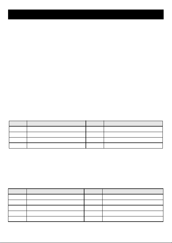
Die Kanalzuordnung ist wie folgt:
Funktionen, die nicht benötigt werden, sollten unkodiert bleiben. Die Kodierung des
DSU 8 kann ohne Versorgungsspannung sowie ohne Dupline-Signal vorgenommen
werden. Sie bleibt dauerhaft erhalten, kann aber jederzeit überschrieben werden.
3. Inbetriebnahme
Die Installation darf nur von einer autorisierten Fachkraft vorgenommen werden. Bei
der Installation ist das Anschlussschema zu beachten. Alle anzuschließenden Leitun-
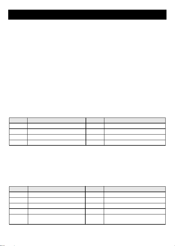
gen müssen spannungsfrei sein. Folgende Tabelle zeigt die Anschlussbelegung:
Kanal Beschreibung Kanal Beschreibung
1 Eingangssignal 1 5 Eingangssignal 5
2 Eingangssignal 2 6 Eingangssignal 6
3 Eingangssignal 3 7 Eingangssignal 7
4 Eingangssignal 4 8 Eingangssignal 8
Klemme Beschreibung Klemme Beschreibung
1.1/1.5 Eingangssignal 1 (IN 1) 1.2/1.6 Eingangssignal 5 (IN 5)
2.1/2.5 Eingangssignal 2 (IN 2) 2.2/2.6 Eingangssignal 6 (IN 6)
3.1/3.5 Eingangssignal 3 (IN 3) 3.2/3.6 Eingangssignal 7 (IN 7)
4.1/4.5 Eingangssignal 4 (IN 4) 4.2/4.6 Eingangssignal 8 (IN 8)
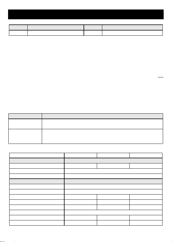
1.3 Dupline Signalleiter - (Dupline-) 1.7 Dupline Signalleiter + (Dupline+)