Technische Daten
SITU
Steuerfunktion
Zentral-Memory-Ein
Relais-Ein
Memory-Ein , Relais-Ein
Memory-Aus , Relais-Aus
…
Zentral-Aus , Relais-Aus
Relais-Ein
1…10-V-Schnittstelle
Ausführung Halbleiterausgang, galvanisch von
Betriebs- und Netzspannung getrennt
Belastbarkeit
Kontrollausgang
externe Schaltstellungsanzeige
Ausführung Halbleiterausgang
Belastbarkeit
Relaisausgang
Ausführung
Nennspannung
Nennstrom
Schaltstellungs-
anzeige durch interne Leuchtdiode
Schutzart
Klemmen Bügelklemme
max. Klemmbereich
min. Draht-
durchmesser
Umgebungs-
temperatur
Bauvorschriften
Lastfaktoren in der SI-Gebäudeleittechnik
Eingangslastfaktor
Ausgangslastfaktor
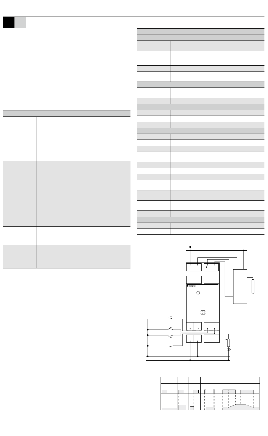
Schaltbilder
A2 A1A4 A3
SITU
1.1 1.5
2.72.31.3 1.7
L1
N
2.1 2.5
zentral ein
zentral aus
(central off)
(central on)
Memory ein
(memory on)
18 15 - +
B1
1.4 B1
1.8
dimmen / ein / aus
(dimming / on / off)
24 V DC
0 V DC
2,2 - 5,6 k
externe Anzeige
(external display)
1...10 V
EIN
NL
+
-
EVG
1...10 V
X
VTastsignalumsetzer SITU
A1 A4 A3
A2
z. B. 40 % 100 %
z. B. 40 %z. B. 40 %
Steuereingang
Steuerspannung
Ausgang
Memory ein Zentral ein Zentral aus
einaus dimmendimmen
t < 600 ms t > 600 ms t > 600 ms
central on central off on off dimming dimming
control input
control voltage
memory on
output
Montage- und Bedienungsanleitung
SITU-Tastsignalumsetzer mit 1…10-V-Schnittstelle
Allgemeine Hinweise
Dimmer, die mit einer 1…
Steuerfunktion
-
Steuereingänge SITU
Steuereingang: Memory-Ein
…-
wird eingeschaltet.
Kontrollausgang: Ein / Aus
Leuchtdiode signalisiert. Mit dem Ausgangssignal am
externe Schaltstellungsanzeige erfolgen.
Steuereingang: Memory-Ein/-Aus/Dimmen
…
Rampencharakteristik, d. h. steigend bzw. fallend bis zum
wird bei einem Ausschaltimpuls gespeichert und kann durch
-
entgegengesetzt zur Laufrichtung, die zum Erreichen des
Steuereingang: Zentral-Aus
Die Schaltstellung Zentral-Aus wird durch einen Steuer-
wird abgeschaltet.
Steuereingang: Zentral-Ein
…
das Lastrelais wird eingeschaltet.
Montage
Montage erfolgt durch Aufschnappen auf eine Tragschiene.
-
-
lers, gleichen Typs und gleicher Leistung verwendet werden.
Anforderungen an die Befehlsgeräte
-
Bei handelsüblichen Tastern mit mechanischen Kontakten sind diese Anforderungen
Gewährleistung
-
-
Doepke
||
DE EN


