Doepke Dupline DRD 2 User manual

3931203/02/07/C
Doepke
Dupline
Rauch- und Brandmelder DRD 2
Smoke and Fire Detector DRD 2
Bedienungsanleitung
Operating Instructions

2 3931203/02/07/C
Doepke
Inhaltsverzeichnis
1. Allgemeines ........................................................................................... 3
2. Kodierung .............................................................................................. 3
3. Montage................................................................................................. 3
5. LED-Anzeige ......................................................................................... 5
6. Sicherheitshinweise............................................................................... 5
7. Wartung und Pflege............................................................................... 5
8. Garantie................................................................................................. 5
9. Technische Daten.................................................................................. 6
10. Kontakt .................................................................................................. 6
20. Anschlussschema / Connection Diagram............................................ 11
21. Maße / Dimensions.............................................................................. 12
Table of Contents
11. General Information............................................................................... 7
12. Coding ................................................................................................... 7
13. Mounting................................................................................................ 7
14. Test Button ............................................................................................ 8
15. LED-Indicators....................................................................................... 9
16. Safety Instructions ................................................................................. 9
17. Maintenance and Care .......................................................................... 9
18. Guarantee.............................................................................................. 9
19. Technical Data..................................................................................... 10
20. Anschlussschema / Connection Diagram............................................ 11
21. Maße / Dimensions.............................................................................. 12
22. Contact ................................................................................................ 12

3931203/02/07/C 3
Doepke
Bedienungsanleitung
Dupline Rauch- und Brandmelder DRD 2
1. Allgemeines
Der optische Brandmelder DRD 2 ist eine Komponente des Dupline Installationssystems
und ermöglicht die frühzeitige Erkennung sowohl von Schwelbränden als auch von of-
fenen Bränden mit Rauchentwicklung. Er arbeitet nach dem bewährten Streulichtprin-
zip. Lichtsender und -empfänger sind in der Messkammer so angeordnet, dass das
Lichtbündel des Senders nicht direkt in den Empfänger treffen kann. Erst das an Schwe-
beteilen gestreute Licht (Tyndall-Effekt) gelangt zum Empfänger und wird in ein elektri-
sches Signal umgesetzt. Aufgrund dieser Bauweise benötigt er kein radioaktives
Präparat.
Der DRD 2 benötigt lediglich den Anschluss der Dupline Signalleiter. Sowohl die Brand-
meldung als auch das Statussignal, das den korrekten Anschluss des Brandmelders an
die eingebaute Dupline-Platine signalisiert, werden über den Dupline-Bus übertragen.
Die LED im Gehäuse des DRD 2 zeigt neben dem Alarm auch den funktionsfähigen Zu-
stand des Gerätes an.
2. Kodierung
Mit dem Handkodiergerät DHK 1 kann, über die nach Aufdrehen des Gehäusedeckels
zugängliche 4-polige Stiftleiste D der Platine A (siehe Kapitel 20 “Anschlussschema /
Connection Diagram” auf Seite 11), jedem Kanal jede beliebige Adresse zwischen A1
und P8 zugeordnet werden. Die Aufteilung der Kanäle ist wie folgt::
Kanäle, die nicht benötigt werden, sollten unkodiert bleiben. Die Kodierung des DRD 2
kann ohne Verbindung zum Dupline-Bus vorgenommen werden und erfolgt mithilfe des
Flachstecker-Kodierkabels DKP 2. Auf richtige Polarität des Steckers (siehe Anschluss-
schema) muss geachtet werden. Die Kodierung bleibt dauerhaft erhalten, kann aber je-
derzeit überschrieben werden.
3. Montage
3.1. Anschluss
Die Installation darf nur von einer autorisierten Fachkraft vorgenommen werden.
Zur Montage ist der Sockel des DRD 2 durch Linksdrehung vom Gehäuse zu trennen.
Der Anschluss an den Dupline-Bus erfolgt, wie im Anschlussschema dargestellt, direkt
an den Anschlussklemmen B auf der senkrecht stehenden Platine A (Dupline Signallei-
Kanal Beschreibung Kanal Beschreibung
1 Alarmsignal, aktiv bei Alarm 5 Nicht verwendet.
2Statussignal
a
a. Aktiv bei angeschlossenem Bussignal und Rauchmelder: alle 50 s ist dieser Kanal für 1
Zyklus aktiv.
6 Nicht verwendet.
3 Nicht verwendet. 7 Nicht verwendet.
4 Nicht verwendet. 8 Nicht verwendet.

4 3931203/02/07/C
Doepke
ter + an rot markierter Klemme, siehe Kapitel 20 “Anschlussschema / Connection Dia-
gram” auf Seite 11). Dazu muss die Platine aus der Halterung gezogen und nach dem
Anschluss wieder eingesetzt werden.
ACHTUNG!
Diese Platine ist ungeschützt. Statische Ladungen des Körpers können beim Berühren
der Platine dessen Bauteile zerstören. Führen Sie deshalb vor dem Entfernen und Wie-
dereinsetzen der Platine eine Entladung durch, indem Sie geerdete Gegenstände mit
der Hand berühren.
Beim Einsetzen ist darauf zu achten, dass die Platine in der Führung des Gehäuses liegt
und die Ausrichtung so ist, dass die 5-polige Stiftleiste C in die vorgesehenen Löcher ein-
geführt ist. Zudem muss das Kabel durch die Aussparung E geführt werden.
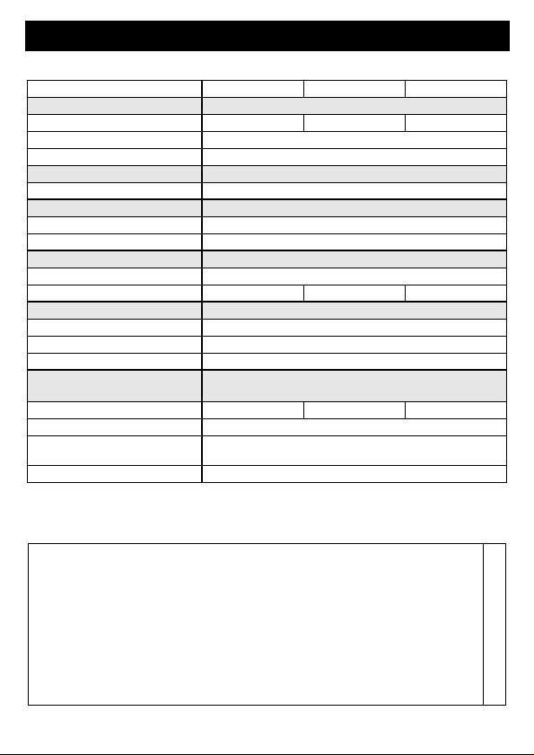
Folgende Tabelle zeigt die Anschlussbelegung:
Verbindungen zwischen dem Dupline-Signal und dem Erdpotenzial führen zu Störungen
und sind nicht zulässig. Auf die richtige Polarität des Dupline-Signals ist zu achten.
3.2. Auswahl der Montageorte
Der Brandmelder muss an der Decke möglichst in Zimmermitte montiert werden. Ein
DRD 2 kann einen Raum von maximal 60 m² Grundfläche und einer Höhe von bis zu 6 m
überwachen. In Fluren und schmalen Gängen (bis 3 m Breite) überwacht der Melder
7,5 m nach jeder Seite. Ein Mindestabstand von 0,5 m zu Wänden und Einrichtungen ist
einzuhalten.
Als Mindestschutz sollte ein DRD 2 vor dem Schlafzimmer bzw. in jedem Stockwerk vor-
gesehen werden. Größerer Schutz ist jedoch gegeben, wenn in jedem Zimmer ein Mel-
der vorhanden ist (außer in Küche und Bad - hier sind Täuschungsalarme durch
Dampfentwicklung möglich).
3.3. Ungeeignete Montageorte
Montieren Sie den Brandmelder
• nicht in der Nähe von Lüftungsleitungen und starker Zugluft
• nicht direkt in der Dachspitze (Abstand von 30 cm zur Dachspitze einhalten)
• nicht in Räumen, in denen unter normalen Bedingungen starker Dampf, Staub oder
Rauch entsteht (z.B. in Werkstätten, Bädern oder Küchen)
• nicht in Räumen, in denen die Temperatur über +40 °C oder unter +5 °C liegt.
4. Prüftaste
Mithilfe der Prüftaste am DRD 2 kann ein Testalarm ausgelöst werden. Dabei wird die
interne Betriebsbereitschaft durch Aufleuchten der LED signalisiert und die Bereitschaft
am Dupline-Bus durch Schalten des eingestellten Kanals.
Klemme Beschreibung Klemme Beschreibung
Rot (1) Dupline Signalleiter +
(Dupline +) Grau (2) Dupline Signalleiter -
(Dupline -)

3931203/02/07/C 5
Doepke
5. LED-Anzeige
Die frontseitig angebrachten LEDs signalisieren den Zustand des Gerätes:
6. Sicherheitshinweise
• Der Brandmelder darf nicht mit Farbe überstrichen werden.
• Brandmelder löschen keinen Brand. Bei Alarm ist der Brandherd aufzusuchen und
gegebenenfalls die Feuerwehr zu alarmieren.
• Der DRD 2 erkennt den Rauch eines Brandes und nicht die Flamme selbst.
• Der Brandmelder überwacht einen bestimmten Bereich im Umfeld seines Montage-
ortes und nicht unbedingt andere Zimmer oder Stockwerke (siehe auch Kapitel 3.2
“Auswahl der Montageorte” auf Seite 4). Installieren Sie daher ausreichend viele
Brandmelder, um optimalen Schutz zu gewährleisten.
7. Wartung und Pflege
Um die Funktionssicherheit des DRD 2 zu erhalten, beachten Sie bitte folgende Hinwei-
se:
• Überprüfen Sie monatlich die Funktion durch Drücken des Testknopfes. Der Alarm
muss sowohl am Gerät (kurzes Blinken der LED im 5s-Abstand) als auch über den
Dupline-Bus gemeldet werden.
• Wischen Sie den Brandmelder halbjährlich mit einem feuchten Tuch ab.
• Wechseln Sie den Brandmelder nach etwa 10 Jahren aus.
8. Garantie
Für fachgerecht montierte, unveränderte Geräte gewähren wir ab Kauf durch den End-
verbraucher die gesetzliche Gewährleistungsfrist. Die Garantie bezieht sich nicht auf
Transportschäden sowie Schäden, die durch Kurzschluss oder Überlastung entstanden
sind. Bei Fertigungs- und Materialfehlern, die innerhalb der Gewährleistungsfrist erkannt
werden, leistet unser Werk kostenlosen Ersatz. Bei Öffnen der Messkammer erlischt der
Garantieanspruch.
Anzeige Beschreibung
Rote LED
Kurzes Blinken etwa alle 50 s einmal (Lebenszeichen)
Gerät funktionsbereit.
Kurzes Blinken etwa alle 5 s:
Alarm

6 3931203/02/07/C
Doepke
9. Technische Daten
10. Kontakt
Min. Typ. Max.
Dupline
Stromaufnahme 200 µA 1 mA
Eingangskanäle 2 (Statussignal, Alarmsignal)
Ausgangskanäle Keine
Betriebsspannung
aus Dupline-Signalleiter
Detektor
Art optisch (nach Tyndall-Effekt)
Ansprechschwelle nach prEN 12239(95)
Anschlüsse
Art Steckschraubklemmen
Klemmbereich 0,4 mm ∅1,5 mm²
Gehäuse
Art deckenmontierbares Gehäuse
Maße ∅ 80 x 80 (in mm)
Material Polycarbonat
Allgemeine technische
Daten
Betriebstemperatur +5°C +40°C
Luftfeuchtigkeit 20%..80% (Betauung nicht zulässig)
Schutzart / Normen IP 42, dieses Modell basiert auf ein Gerät mit
der VdS-Anerkennung G 299084
Bestellnummer, -bezeichnung 09 501 150, DRD 2
Sollten Sie Fragen zu diesem Produkt oder zum Dupline-System haben, wen-
den Sie sich bitte an:
Doepke
Schaltgeräte GmbH & Co. KG
Stellmacherstraße 11
D-26506 Norden, Germany
Tel.: +49 (0) 4931/1806-0
Fax: +49 (0) 4931/1806-101
E-mail:
Internet:
http://www.doepke.de
3931203/02/07/C

3931203/02/07/C 7
Doepke
Operating Instructions
Dupline Smoke and Fire Detector DRD 2
11. General Information
The optical smoke detector DRD 2 is a component of the Dupline building management
system and allows an early detection of smouldering fires as well as flaming fires that de-
velop smoke. It operates on the proven light scatter principle. Inside the sensing cham-
ber a light source and a light sensor are arranged so that light normally does not fall on
the sensor. It is only when airborne particles enter the chamber that light is scattered onto
the sensor (Tyndall effect) to produce the electrical signal. This design means that no ra-
dioactive source is required.
The DRD 2 only needs the connection to the Dupline conductors. The smoke alarm as
well as the status signal, which indicates the correct connection between the smoke de-
tector and the in-built Dupline circuit board, are transmitted via the Dupline bus. Besides
the alarm, the LED in the housing of the DRD 2 shows also the state of function of the de-
vice.
12. Coding
At the 4-pole flat pack connector D of the PCB A, which is accessible after screwing off
the base, it is possible to assign any addresses between A1 and P8 to each channel, us-
ing the hand encoder DHK 1 (see chapter 20 “Anschlussschema / Connection Diagram”
on page 11). The channel allocation is as follows:
Channels, which are not used, should not be encoded. The encoding of the DRD 2 can
be done without any connection to the Dupline bus and is carried out using the flat pack
encoding cable DKP 2. The correct polarity of the plug has to be observed (see connec-
tion diagram). The encoding remains permanently but can be overwritten at any time.
13. Mounting
13.1. Connection
Only an authorized expert is allowed to carry out the installation. Before mounting the
base of the DRD 2 has to be removed from the housing by screwing it anticlockwise. The
connection to the Dupline bus is done at the screw terminals B on the vertically mounted
PCB A (Dupline signal conductor + at the red marked screw terminal, see chapter
20 “Anschlussschema / Connection Diagram” on page 11). For accessing the PCB, it
Channel Description Channel Description
1 Alarm signala
a. Active on occurance of an alarm
5 Not assigned
2 Status signalb
b. Active when bus signal lines are connected and smoke detector is working: every 50s this
channel is active for 1 cycle.
6 Not assigned
3 Not assigned 7 Not assigned
4 Not assigned 8 Not assigned

8 3931203/02/07/C
Doepke
has to be removed from its fastener at first.
CAUTION!
This PCB is unprotected. Static charges of the human body may destroy the PCBs’ com-
ponents when touching it. Therefor, carry out a discharge by touching grounded objects
before removal and reinsertion of the PCB.
After connecting the bus, the PCB has to be reinserted, where it must be observed, that
the PCB correctly is fixed in the fastener and the orientation of the PCB is so, that the 5-
pin terminal C runs into the wholes of the base PCB. In addition, the Dupline conductors
have to be passed through the groove E of the PCB. The following table shows the con-
nections:
Short circuits between the Dupline signal conductors and the earth potential lead to dis-
turbances and have to be avoided. The correct polarity of the Dupline signal has to be ob-
served.
13.2. Choice of Mounting Location
The smoke detector must be fixed to the ceiling as near as possible to the centre of the
room. One DRD 2 can monitor a room with a maximum floor area of 60 m² with a ceiling
hight of up to 6 m. In hallways and narrow corridors (up to 3 m width) the detector mon-
itors a distance up to 7.5 m in each direction. A gap of at least 0.5 m must be maintained
from walls and furniture.
To achieve a minimum protection, one DRD 2 should be installed in front of the of each
sleeping area respectively in each floor. A better protection will be rached if one smoke
detector is present in every room (except for the kitchen and the bath - here, false alarms
are possible due to steam development).
13.3. Unsuitable Locations
Never install the smoke detector
• near to ventilation ducting or strong draughts
• directly in the apex of pitched roofs (a minimum distance of 30 cm from the apex
must be kept)
• in rooms where - under normal conditions - a lot of steam, dust or smoke is present
(for example in workshops, bathrooms and laundry rooms)
• in rooms where the temperature rises above +40 °C or falls below +5 °C.
14. Test Button
With the test button at the DRD 2, the test alarm can be released. Doing so, the internal
operating readiness is signalled by the LED and the readiness on the Dupline bus by
switching the adjusted channel.
Terminal Description Terminal Description
Red (1) Dupline signal conductor +
(Dupline +) Gray (2) Dupline signal conductor -
(Dupline -)

3931203/02/07/C 9
Doepke
15. LED-Indicators
The LEDs in the front indicate the condition of the device:
16. Safety Instructions
• The smoke detector must not be painted.
• Smoke detectors do not extinguish fires. If an alarm occurs, the source of the fire
must be located and, if necessary, the fire brigade alerted.
• The DRD 2 responds to the smoke of a fire, not to the flame itself.
• The smoke detector only monitors a defined area in its vicinity and will not neces-
sarily monitor another room or another floor (see also chapter 13.2 “Choice of
Mounting Location” on page 8). Therefor install a sufficient number of smoke detec-
tors to ensure optimum protection.
17. Maintenance and Care
To ensure proper functioning of the DRD 2, please pay attention to the following points:
• Monthly test the function by pressing the test button. The alarm must be indicated
at the device (short blinking of the LED in 5s-pulses) as well as on the Dupline bus.
• Wipe the smoke detector half-yearly with a damp cloth.
• Replace the smoke detecor after about 10 years of service.
18. Guarantee
All professionally installed, unaltered devices are covered by warranty during the statu-
tory guarantee period from the day of purchase by the end user. The guarantee is not ap-
plicable to damage incurred during transport or caused by short-circuit or overloading. In
the event of defects in workmanship or material, which are discovered within the guar-
antee period, the company will provide a replacement free of charge. The guarantee will
be rendered null and void if the sensing chamber is opened or the device is tampered
with.
Indicator Description
Red LED
Short blinking approx. one time every 50 s (life signal)
Device is functioning.
Short blinking approx. one time every 5 s
Alarm

10 3931203/02/07/C
Doepke
19. Technical Data
Min. Typ. Max.
Dupline
Current input 200 µA 1 mA
Input channels 2 (status signal, alarm signal)
Output channels None
Operating voltage
from Dupline signal conductors
Detector
Type optical (acc. to Tyndall-Effect)
Response level to prEN 12239(95)
Terminals
Type plug/screw terminals
Contact area 0.4 mm ∅1.5 mm²
Housing
Type housing for ceiling fitting
Dimensions ∅ 80 x 80 (in mm)
Material Polycarbonate
General technical data
Ambient temperature +5°C +40°C
Atm. humidity 20%..80% (exposure to dew not permissible)
Encl. protection type /
standards
IIP 42, this model bases on a device with the
VdS-Certification G 299084
Order number, description 09 501 150, DRD 2

3931203/02/07/C 11
Doepke
20. Anschlussschema / Connection Diagram
Dupline +
Dupline -
D
B
C
3931203_1A
A
E
3931203_2A
+
-
Dupline +
Dupline -
UP
D
BC
A
E

12 3931203/02/07/C
Doepke
21. Maße / Dimensions
22. Contact
In case of queries concerning this product or the Dupline system please contact:
Doepke
Schaltgeräte GmbH & Co. KG
Stellmacherstraße 11
D-26506 Norden, Germany
Tel.: +49 (0) 4931/1806-0
Fax: +49 (0) 4931/1806-101
E-mail:
Internet:
http://www.doepke.de
3931203/02/07/C
Table of contents
Languages:
Other Doepke Smoke Alarm manuals