7
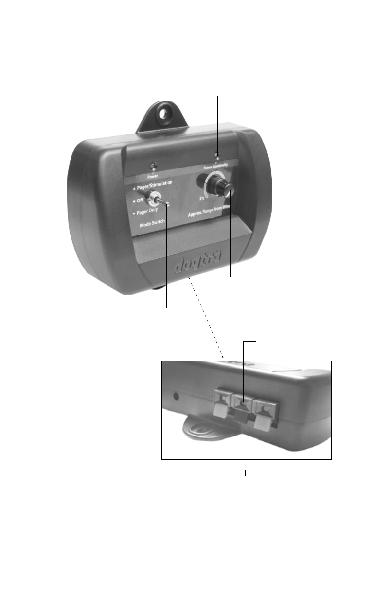
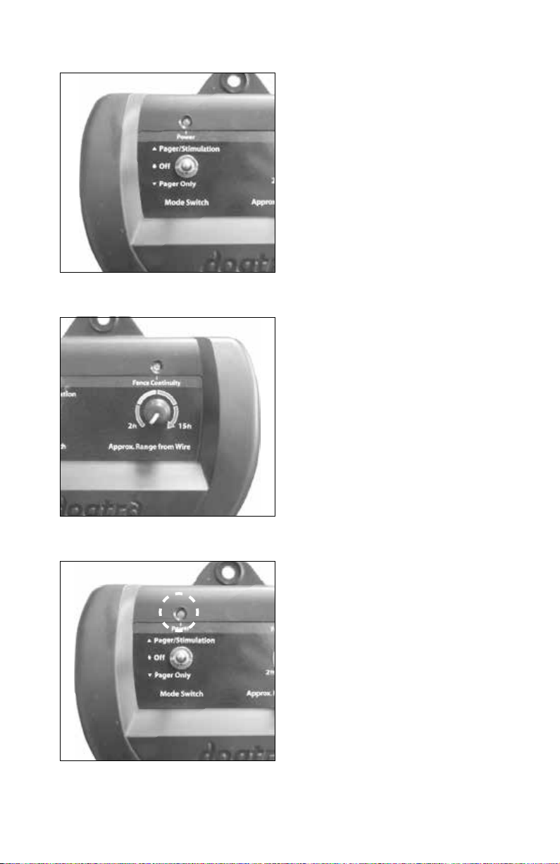
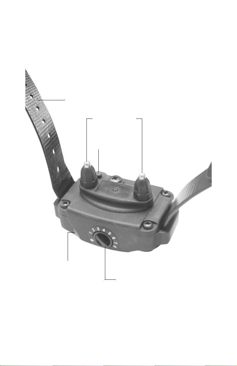
On/Off & Function Selection Switch
The On/Off & Function Selection Switch
has three functions. When the toggle
switch is in the up position, the unit will
give the dog a Pager vibration followed
by stimulation. When the toggle switch
is in the down position, only a Pager
vibration occurs (no stimulation). The
power is off when the toggle switch is
set to the middle position.
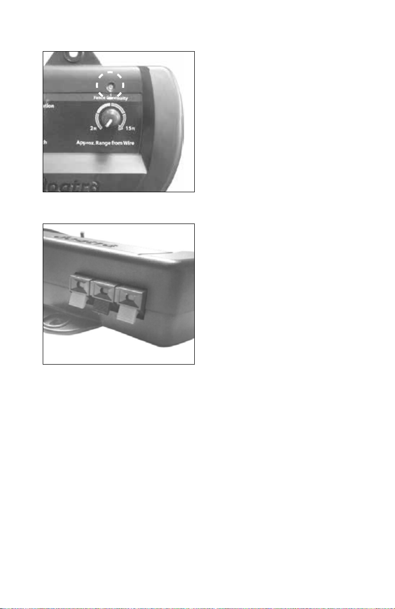
Field Width Adjustment Knob
This knob controls the width of the
signal field (the approximate distance
from the boundary wire to the location
where the receiver first activates).
Turning the knob clockwise increases
the field width, giving your dog a wider
area before the activation begins.
Turning it counter-clockwise decreases
the signal field, thus giving the dog a
shorter area prior to activation.
On/Off Indicator Light
When the On/Off & Function Selection
Switch is either in the up or down
position the on/off indicator light will
be on, indicating that the power is
on. When the switch is in the middle
position the light goes off, indicating
that the power is off. The indicator light
stays on even if a fuse is blown.