Operating Instructions
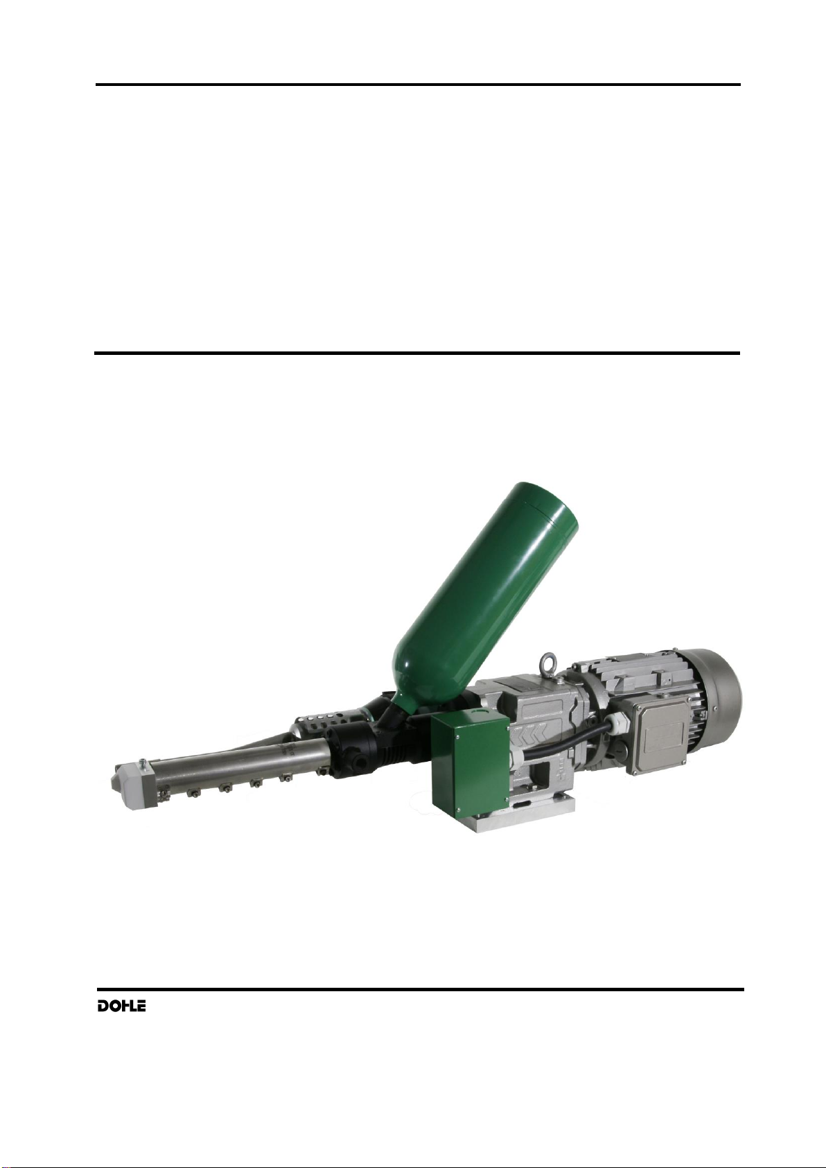
Industrial Extruder DX318 ExOn8 3x400V
Extrusionstechnik GmbH 26
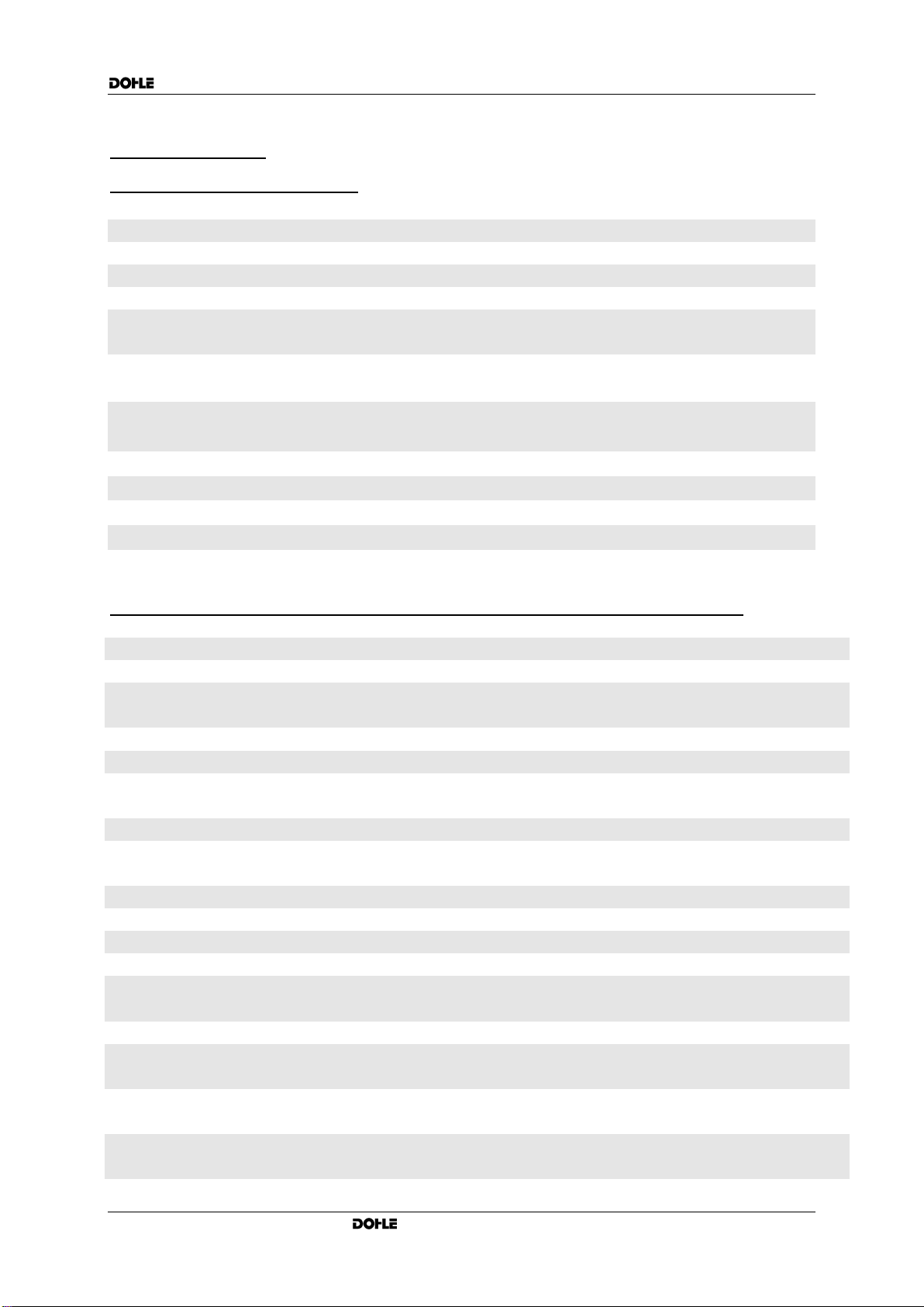
4. Error tracing
Malfunctioning Error–No.
Driving motor does not start 01,02,04,05,06,07,08,09,10,11,12
Driving motor switches off 03,04,05,06,07,08,09,10
Extruder remains cold 04,05,06,07,08,09,15,17
Hot air remains cold 05,07,08,09,12
Hot air temperature is under 11,13
desired value
Extrusion temperature is under 11
desired value
Extruder does not deliver extruded 11
material from the die
Display does not light up 01
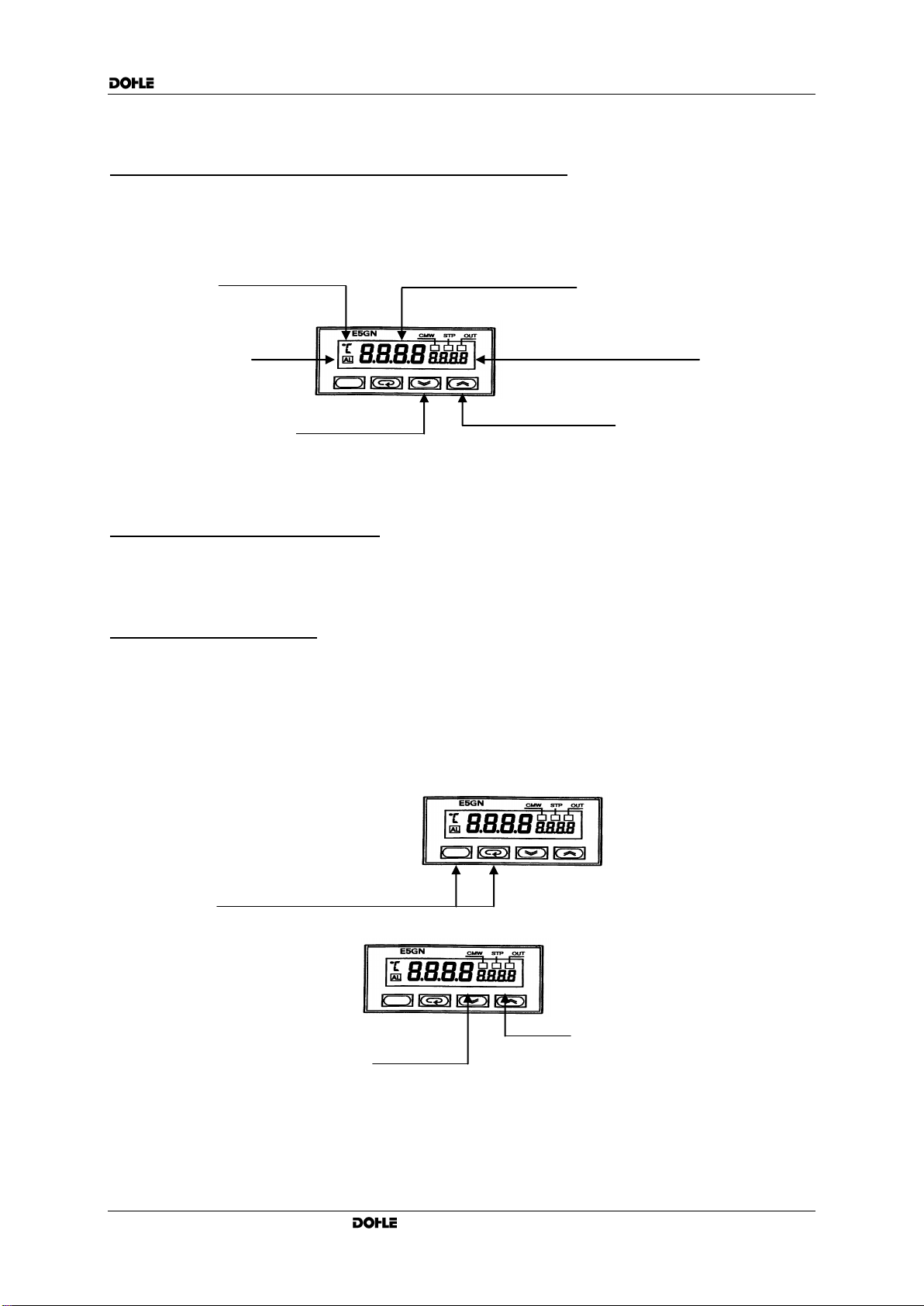
Display shows: S . e r r 15
Display not constant 17
Display shows direction of action: - 18
Error-No. possible cause Elimination of error
Have checked by skilled technician
Extension cord becomes hot
Check cable diameter
Run out cable completely from reel
Thermoelement for mass defective
Thermoelement for air defective
Temperature control unit for mass
defective
Exchange temperature control unit
Temperature control unit for air defective
Exchange temperature control unit
On/Off switch for heating units in OFF
position
Put switch to ON position
Defect on cable connections
Have checked by skilled technician
Carbon brushes of drive motor worn
Replace by new carbon brushes
Pre-heating time too short
External air supply not connected
Connect external air supply
Air flow too high when using external air
supply
Reduce to prescribed quantity
Breakage of monitoring thermoelement
Unsuccessful attempt to change a
blocked parameter
Blockage can only be removed by a
skilled technician
Thermoelement failure or loose
connections
Check thermoelement
Check connections
Sensor incorrectly connected,
+ and –mistaken