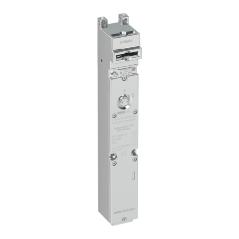
DOLD NE 5020 User manual

1NE 5020 / 23.07.18 de / 004A
Zubehör für
Sicherheitsanwendungen
Magnetschalter kodiert
NE 5020
0265983
Datenblatt / Betriebsanleitung DEUTSCH
E. DOLD & SÖHNE KG
Postfach 1251 • 78114 Furtwangen • Deutschland
Telefon +49 7723 6540 • Fax +49 7723 654356
dold-relays@dold.com • www.dold.com
Original
DE
EN
FR

2NE 5020 / 23.07.18 de / 004A
Inhaltsverzeichnis
Symbol- und Hinweiserklärung..........................................................................................................................................3
Allgemeine Hinweise ........................................................................................................................................................3
Bestimmungsgemäße Verwendung...................................................................................................................................3
Sicherheitshinweise...........................................................................................................................................................3
Funktionsdiagramm...........................................................................................................................................................5
Blockschaltbilder................................................................................................................................................................5
Zulassungen und Kennzeichen .........................................................................................................................................5
Weitere Informationen zu diesem Thema..........................................................................................................................5
Anwendungen....................................................................................................................................................................5
Aufbau und Wirkungsweise ...............................................................................................................................................5
Geräteanschluss................................................................................................................................................................5
Geräteanzeigen.................................................................................................................................................................5
Hinweis..............................................................................................................................................................................5
Technische Daten..............................................................................................................................................................6
Anschluss ..........................................................................................................................................................................6
Standardtype .....................................................................................................................................................................6
Bestellbeispiel....................................................................................................................................................................6
Vorgehen bei Störungen....................................................................................................................................................6
Wartung und Instandsetzung.............................................................................................................................................6
EG-Konformitätserklärung...............................................................................................................................................20

3NE 5020 / 23.07.18 de / 004A
Sicherheitshinweise
WARNUNG
Brandgefahr oder andere thermische Gefahren!
Lebensgefahr, schwere Verletzungsgefahr oder Sachschäden.
• Das Gerät darf nur für die in der mitgeltenden Betriebsanleitung / Daten-
blatt vorgesehenen Einsatzfälle verwendet werden. Die Hinweise in den
zugehörigenDokumentationenmüssenbeachtetwerden.Diezulässigen
Umgebungsbedingungen müssen eingehalten werden.
• Das Gerät darf nur von sachkundigen Personen installiert und in Betrieb
genommen werden, die mit dieser technischen Dokumentation und
den geltenden Vorschriften über Arbeitssicherheit und Unfallverhütung
vertraut sind.
WARNUNG
Funktionsfehler!
Lebensgefahr, schwere Verletzungsgefahr oder Sachschäden.
• Das Gerät darf nur für die in der mitgeltenden Betriebsanleitung / Daten-
blatt vorgesehenen Einsatzfälle verwendet werden. Die Hinweise in den
zugehörigenDokumentationenmüssenbeachtetwerden.Diezulässigen
Umgebungsbedingungen müssen eingehalten werden.
• Das Gerät darf nur von sachkundigen Personen installiert und in Betrieb
genommen werden, die mit dieser technischen Dokumentation und
den geltenden Vorschriften über Arbeitssicherheit und Unfallverhütung
vertraut sind.
!
Achtung!
• Die Sicherheitsfunktion muss bei Inbetriebnahme des Gerätes ausgelöst
werden.
• Bei der Auslieferung ist der magnetische Code von Sensor und Aktor
aufeinander abgestimmt. Erkennbar ist dies durch eine Markierung auf
den Prüfschildern.
• Der Anschluß des Magnetschalters NE 5020 an das Auswertegerät
BG 5925/920 oder LG 5925/920 ist gemäß dem Anschlußbeispiel
vorzunehmen.
• Durch Öffnen des Gehäuses oder eigenmächtige Umbauten erlischt
jegliche Gewährleistung.
GEFAHR
GEFAHR:
Bedeutet, dass Tod oder schwere Körperverletzung eintreten
wird, wenn die entsprechenden Vorsichtsmaßnahmen nicht ge-
troffen werden.
WARNUNG
WARNUNG:
Bedeutet, dass Tod oder schwere Körperverletzung eintreten
kann, wenn die entsprechenden Vorsichtsmaßnahmen nicht
getroffen werden.
VORSICHT
VORSICHT:
Bedeutet, dass eine leichte Körperverletzung eintreten kann,
wenn die entsprechenden Vorsichtsmaßnahmen nicht getroffen
werden.
!
ACHTUNG:
Warnt vor Handlungen, die einen Schaden oder eine Fehlfunktion
des Gerätes, der Geräteumgebung oder der Hard-/Software zur
Folge haben können.
nfo
INFO:
Bezeichnet Informationen, die Ihnen bei der optimalen Nutzung
des Produktes behilflich sein sollen.
Die hier beschriebenen Produkte wurden entwickelt, um als Teil einer
Gesamtanlage oder Maschine sicherheitsgerichtete Funktionen zu über-
nehmen. Ein komplettes sicherheitsgerichtetes System enthält in der
Regel Sensoren, Auswerteeinheiten, Meldegeräte und Konzepte für si-
chere Abschaltungen. Es liegt im Verantwortungsbereich des Herstellers
einer Anlage oder Maschine die korrekte Gesamtfunktion sicherzustellen.
DOLD ist nicht in der Lage, alle Eigenschaften einer Gesamtanlage oder
Maschine, die nicht durch DOLD konzipiert wurde, zu garantieren. Das
Gesamtkonzept der Steuerung, in die das Gerät eingebunden ist, ist vom
Benutzer zu validieren. DOLD übernimmt auch keine Haftung für Empfeh-
lungen, die durch die nachfolgende Beschreibung gegeben bzw. impliziert
werden. Aufgrund der nachfolgenden Beschreibung können keine neuen,
über die allgemeinen DOLD-Lieferbedingungen hinausgehenden Garan-
tie-, Gewährleistungs- oder Haftungsansprüche abgeleitet werden.
Allgemeine Hinweise
Symbol- und Hinweiserklärung
Installation nur durch Elektrofachkraft!
Nicht im Hausmüll entsorgen!
Das Gerät ist in Übereinstimmung mit den national gültigen
Vorgaben und Bestimmungen zu entsorgen.
Aufbewahren für späteres Nachschlagen
Um Ihnen das Verständnis und das Wiederfinden bestimmter Textstellen
und Hinweise in der Betriebsanleitung zu erleichtern, haben wir wichtige
Hinweise und Informationen mit Symbolen gekennzeichnet.
Vor der Installation, dem Betrieb oder der Wartung des Gerätes
muss diese Anleitung gelesen und verstanden werden.
Bestimmungsgemäße Verwendung
Der berührungslos wirkende Magnetschalter NE 5020 eignet sich zur
Stellungsüberwachung von verschiebbaren, drehbaren oder abnehmba-
ren Schutztüren, auch in Fällen starker Verschmutzung oder hygienischer
Anforderungen. Das Gerät ist einsetzbar auch für schwergängige oder
ungenau positionierte Türen.
Verwendbare Auswertegeräte: BG 5925/920 oder LG 5925/920

4NE 5020 / 23.07.18 de / 004A

5NE 5020 / 23.07.18 de / 004A
•verwendbar für Sicherheitsanwendungen in Verbindung mit
einem korrekt installierten und angeschlossenem
Sicherheitsmodul (z. B. BG 5925/920 oder LG 5925/920)
•nach IEC/EN 60 204-1, EN 1088
•2-kanaliges System
•Standardschaltabstände: San ≤5,5 mm
Sab ≥13 mm
•2 Schließer, als Halbleiter, diversitär, redundant
•magnetisch kodiert zur Erhöhung der Manipuliersicherheit
•Anschlußkabel mit Aderendhülsen
•sehr lange Lebensdauer bei häufigen Schaltspielen
•leichte Montage und Wartung
•einsetzbar bei starken Vibrationen
•nicht empfindlich gegen magnetische Fremdfelder
•Schutzart IP 67
•wahlweise Anschlußkabel mit M8 oder M12-Stecker, anschraubbar
•LED als Schaltstellungsanzeige
0231293
Schaltabstand S
[mm]
6
10
Sab
San
Ausgänge 14; 24
LED
An
Aus
* nur bei Code-Übereinstimmung kann der Ausgang aktiv wer
den.
*
t
t
t
M7588_a
Dekoder
Spannungs-
Versorgung
(+)
(-) (-)
(+)
S
Empfänger Kanal 1 Empfänger Kanal 2
Aktor
Sensor M7589
(weiß) A1
Montageversatz y
(gelb) 24 (braun) 14
(grün) A2
Codegeber
Schaltzustände entsprechen dem nicht aktivierten Zustand.
grüne LED: Sensor ist aktiv, Ausgänge sind eingeschaltet
Bei der Auslieferung ist der magnetische Code von Sensor und Aktor
aufeinander abgestimmt. Erkennbar ist dies durch eine Markierung auf
den Prüfschildern.
Der Magnetschalter NE 5020 besteht aus einem Aktor als magnetischer
Codegeber und einem Sensor als Decoder. Die 2 Halbleiterausgänge
schließen, wenn der Sensor die richtige 2-kanalige Kodierung des Aktors
erkennt.Im Auswertegerät werden die Leitungen 14 und 24 auf Querschluß
überwacht. Beim Auftreten eines Fehlers werden die Ausgangskontakte
des Auswertegerätes sicherheitsgerichtet abgeschaltet und ein erneuter
Start wird verhindert. Der Magnetschalter ist gegen Kurzschlußströme und
Spannungsstörimpulse geschützt.
Der Anschluß des Magnetschalters NE 5020 an das Auswertegerät
BG 5925/920 oder LG 5925/920 ist gemäß dem Anschlußbeispiel vorzu-
nehmen.
Der berührungslos wirkende Magnetschalter NE 5020 eignet sich zur
Stellungsüberwachung von verschiebbaren, drehbaren oder abnehmba-
ren Schutztüren, auch in Fällen starker Verschmutzung oder hygienischer
Anforderungen. Das Gerät ist einsetzbar auch für schwergängige oder
ungenau positionierte Türen.
Verwendbare Auswertegeräte: BG 5925/920 oder LG 5925/920
•Datenblatt Auswertegerät BG 5925/920 oder LG 5925/920
für Sicherheitsschalter
Funktionsdiagramm Zulassungen und Kennzeichen
Weitere Informationen zu diesem Thema
Anwendungen
Aufbau und Wirkungsweise
Geräteanschluss
Geräteanzeigen
Hinweis
Blockschaltbilder
Sicherheitstechnik
Zubehör für Sicherheitsanwendungen
Magnetschalter kodiert
NE 5020
Alle Angaben in dieser Liste entsprechen dem technischen Stand zum Zeitpunkt der Ausgabe.
Technische Verbesserungen und Änderungen behalten wir uns jederzeit vor.

6NE 5020 / 23.07.18 de / 004A
Anschluss Signalbeschreibung
A1 Hilfspannung DC 24V
A2 Hilfspannung 0 V
14 Halbleiterausgang
nach Plus schaltend (DC 24 V)
24 Halbleiterausgang
nach Null schaltend (0 V)
Technische Daten Anschluss
Standardtype
Bestellbeispiel
Vorgehen bei Störungen
Wartung und Instandsetzung
Eingang
Nennspannung A1/A2 UN: DC 24 V
Spannungsbereich: 0,9 ... 1,1 UN
Nennverbrauch: 27 mA
Sichere Schaltabstände
San: ≤5,5 mm
Sab: ≥13 mm
undefinierter Zustand: 5,6 ... 12,9 mm
max. Montageversatz: y = ± 1 mm
Aktor Aktor
Sensor Sensor
San Sab
M8348
Ausgang
NE 5020.92 2 Halbleiterausgänge
Ausgang 14: + DC 24 V ( nach Plus-schaltend)
Ausgang 24: 0V ( nach Null-schaltend)
Reaktionszeit: max. 50 ms
Thermischer Strom Ith:max. 200 mA
Elektrische Lebensdauer: 50 x 106Schaltspiele
Zulässige Schalthäufigkeit: 3 600 Schaltspiele / h
Allgemeine Daten
Nennbetriebsart: Dauerbetrieb
Temperaturbereich
Betrieb: - 25 ... + 60 °C
Lagerung: - 25 ... + 60 °C
Betriebshöhe: < 2.000 m
Zugentlastung: IEC/EN 60 669-1 (Anhang B)
EMV
Statische Entladung (ESD): 8 kV (Luftentladung) IEC/EN 61 000-4-2
HF-Einstrahlung: 10 V/m IEC/EN 61 000-4-3
Schnelle Transienten: 4 kV IEC/EN 61 000-4-4
Stoßspannungen (Surge)
zwischen
Versorgungsleitungen: 0,5 kV IEC/EN 61 000-4-5
zwischen Leitung und Erde: 4 kV IEC/EN 61 000-4-5
HF-leitungsgeführt: 10 V IEC/EN 61 000-4-6
Funkentstörung: Grenzwert Klasse B EN 55 011
Schutzart
Gehäuse: IP 67 IEC/EN 60 529
Gehäuse: Thermoplast mit V0-Verhalten
nach UL Subj. 94
Rüttelfestigkeit: Amplitude 0,35 mm
Frequenz 10 ... 55 Hz, IEC/EN 60 068-2-6
Klimafestigkeit: 25 / 060 / 04 IEC/EN 60 068-1
Kabelanschlüsse: 4 drahtig mit Aderendhülsen
weiß: + 24 V;
grün: 0 V
braun: +24 V Schaltsignal
gelb: 0 V Schaltsignal
oder M8/M12-Stecker, Pinbelegung
siehe Zeichnung Anschlußbuchse
Kabellänge:
mit Aderendhülse: 4 m, nach UL Style 2464
mit M8/M12-Stecker: 30 cm, nach UL Style 2464
Befestigung: Schraube M4
mit Unterlagscheibe EN ISO 7092
Montage, Drehmoment: max. 1,1 Nm
Nettogewicht:
Aktor: 45 g
Sensor: 95 g
Geräteabmessungen
Breite x Höhe x Tiefe:
Aktor: 92 x 24 x 18 mm
Sensor: 92 x 24 x 23,5 mm
NE 5020.92 DC 24V
Artikelnummer: 0051641 (für Sensor und Aktor)
•Ausgang: 2 Halbleiterausgänge
•Nennspannung UN: DC 24 V
•Anschlußkabel: 4 m, mit Aderendhülse
NE 5020 .92 /_ _ _ /_ _ _ _ DC 24 V
Nennspannung
Kodierung zur Erhöhung der
Manipuliersicherheit
0011
0110
1001
1100
Anschlussart
0: Standard
1: Anschlusskabel mit
M12-Stecker, anschraubbar
(auf Anfrage)
2: Anschlusskabel mit
M8-Stecker, anschraubbar
(auf Anfrage)
Schaltabstand
0: San = 5,5 mm; Sab = 13 mm
1: San = 4 mm; Sab = 10 mm
Kabellänge
0: 300 mm
1: 1000 mm
Q: 100 mm
Ausgang
Gerätetype
Fehler mögliche Ursache
LED leuchtet nicht - Versorgungsspannung nicht
angeschlossen
- Abstand von Aktor zu Sensor
zu groß
- Das Gerät enthält keine Teile, die einer Wartung bedürfen.
- Bei vorliegenden Fehlern das Gerät nicht öffnen, sondern an den
Hersteller zur Reparatur schicken.
E. DOLD & SÖHNE KG • D-78114 Furtwangen
e-mail: dold-relays
@dold.com • internet: http://www.dold.com
•
Postfach 1251 • Telefon 0 77 23 / 654-0 • Telefax 0 77 23 / 654-356

7NE 5020 / 23.07.18 en / 004A
Accessories for
Safety Applications
Magnetic Switch coded
NE 5020
Datasheet / Operating Instructions ENGLISH
E. DOLD & SÖHNE KG
P.O. Box 1251 • D-78114 Furtwangen • Germany
Tel: +49 7723 6540 • Fax +49 7723 654356
Translation
of the original instructions
0265983

8NE 5020 / 23.07.18 en / 004A
Contents
Symbol and Notes Statement............................................................................................................................................9
General Notes ...................................................................................................................................................................9
Designated Use.................................................................................................................................................................9
Safety Notes ......................................................................................................................................................................9
Function Diagram ............................................................................................................................................................11
Block Diagrams ...............................................................................................................................................................11
Approvals and Markings ..................................................................................................................................................11
Additional Information about this topic.............................................................................................................................11
Applications .....................................................................................................................................................................11
Function...........................................................................................................................................................................11
Connections.....................................................................................................................................................................11
Indicators.........................................................................................................................................................................11
Notes ...............................................................................................................................................................................11
Technical Data.................................................................................................................................................................12
Connection ......................................................................................................................................................................12
Standard Type..................................................................................................................................................................12
Ordering Example ...........................................................................................................................................................12
Troubleshooting ...............................................................................................................................................................12
Maintenance and repairs.................................................................................................................................................12
CE-Declaration of Conformity..........................................................................................................................................20

9NE 5020 / 23.07.18 en / 004A
Safety Notes
WARNING
Risk of fire or other thermal hazards!
Danger to life, risk of serious injuries or property damage.
• The device may only be used for the applications described in the mu-
tually applicable operating instructions / data sheet. The notes in the
respective documentation must be heeded. The permissible ambient
conditions must be observed.
• The device may only be installed and put into operation by experts who
are familiar with this technical documentation and the applicable health
and safety and accident prevention regulations.
WARNING
Functional error!
Danger to life, risk of serious injuries or property damage.
• The device may only be used for the applications described in the mu-
tually applicable operating instructions / data sheet. The notes in the
respective documentation must be heeded. The permissible ambient
conditions must be observed.
• The device may only be installed and put into operation by experts who
are familiar with this technical documentation and the applicable health
and safety and accident prevention regulations.
!
Attention!
• The safety function must be triggered during commissioning.
• The code of transmitter and receiver are identically on delivery.This can
be verified by a mark on the test sticker.
• The NE 5020 is connected to the control unit BG 5925/920 or
LG 5925/920 according to the application example.
• Opening the device or implementing unauthorized changes voids any
warranty
DANGER
DANGER:
Indicates that death or severe personal injury will result if
proper precautions are not taken.
WARNING
WARNING:
Indicates that death or severe personal injury can result if
proper precautions are not taken.
CAUTION
CAUTION:
Indicates that a minor personal injury can result if proper
precautions are not taken.
!
ATTENTION:
Warns against actions that can cause damage or malfunction of the
device, the device environment or the hardware / software result.
nfo
INFO:
Referred information to help you make best use of the product.
Symbol and Notes Statement
The installation must only be done by a qualified electrican!
Do not dispose of household garbage!
The device must be disposed of in compliance with nationally
applicable rules and requirements.
To help you understand and find specific text passages and notes in the
operating instructions, we have important information and information
marked with symbols.
Before installing, operating or maintaining this device, these in-
structions must be carefully read and understood.
The product hereby described was developed to perform safety functions
as a part of a whole installation or machine. A complete safety system
normally includes sensors, evaluation units, signals and logical modules
for safe disconnections. The manufacturer of the installation or machine
is responsible for ensuring proper functioning of the whole system. DOLD
cannot guarantee all the specifications of an installation or machine that
was not designed by DOLD. The total concept of the control system into
which the device is integrated must be validated by the user. DOLD also
takes over no liability for recommendations which are given or implied in
the following description. The following description implies no modification
of the general DOLD terms of delivery, warranty or liability claims.
General Notes
Designated Use
The magnetic switch NE 5020 is suitable to detect the closed state of sa-
fety gates, sliding gates and removable covers also under rough ambient
conditions or for hygienic requirements. The corresponding control unit is
BG 5925/920 or LG 5925/920
Storage for future reference

10 NE 5020 / 23.07.18 en / 004A

11 NE 5020 / 23.07.18 en / 004A
Function Diagram Approvals and Markings
Additional Information about this topic
Applications
Function
Connections
Indicators
Notes
Block Diagrams
Safety Technique
Accessories for Safety Applications
Magnetic Switch coded
NE 5020
•Usable for safety application by using a correctly installed and
connected, security module (e. g. BG 5925/920 or LG 5925/920)
•According to IEC/EN 60 204-1, EN 1088
•2 channel system
•Standard switching distance: San ≤5.5 mm
Sab ≥13 mm
•2 NO semiconductor outputs providing diversity and redundancy
•Magnetic coded, safe against manipulation
•Open end connection wires
•M8 or M12 connector as option
•Long service life
•Easy to mount
•Resistant against vibration
•Not sensitive to external magnetic fields
•Protection class IP 67
•LED indicator
0233459
Sensing
distanceS[mm]
3
7
Sab
San
Outputs 14; 24
LED
On
Off
* only when transmitter is used with the corresponding code
*
t
t
t
M7741
Decoder
Supply
(+)
(-) (-)
(+)
S
Receiver channel 1 Receiver channel 2
Transmitter
Receiver M7742
(white) A1
Mounting difference y
(yellow) 24 (brown) 14
(green) A2
Code
The magnetic switch NE 5020 includes a magnetic coded transmitter and
a receiver as decoder. The semiconductor outputs close, when the recei-
ver recognises the right code from the transmitter. The control unit detects
cross faults on the lines 14 and 24. The control unit is switched off when
a fault is detected and inhibits a new start. The switch is protected against
short circuits and peak voltages.
The NE 5020 is connected to the control unit BG 5925/920 or LG 5925/920
according to the application example below.
The magnetic switch NE 5020 is suitable to detect the closed state of sa-
fety gates, sliding gates and removable covers also under rough ambient
conditions or for hygienic requirements. The corresponding control unit is
BG 5925/920 or LG 5925/920.
Drawing shows contacts in inactive state
green LED: switch is active, outputs switched on
The code of transmitter and receiver are identically on delivery. This can
be verified by a mark on the test sticker.
•Data sheet control unit BG 5925/920 or LG 5925/920 for safety switch
All technical data in this list relate to the state at the moment of edition. We reserve the right for
technical improvements and changes at any time.

12 NE 5020 / 23.07.18 en / 004A
ConnectionTechnical Data
Input
Nominal voltage A1/A2 UN: DC 24 V
Voltage range: 0.9 ... 1.1 UN
Nominal consumption: 27 mA
Operating distance
Son: ≤5.5 mm
Soff: ≥13 mm
undefined situation: 5.6 ... 12.9 mm
Max. mounting difference: y = ± 1 mm
actuator actuator
sensor sensor
San Sab
M8351_a
Output
NE 5020.92 2 semiconductor outputs
Output 14: + DC 24 V (+ switching)
Output 24: 0V (- switching)
Reaction time: max. 50 ms
Thermal current Ith:max. 200 mA
Electrical life: 50 x 106switching cycles
Permissible switching
frequency: 3 600 switching cycles / h
General Data
Operating mode: Continuous operation
Temperature range:
Operation: - 25 ... + 60 °C
Storage: - 25 ... + 60 °C
Altitude: < 2,000 m
Strain relieve:
VDE 0623, IEC/EN 60 669-1 (appendix B)
EMC
Electrostatic discharge: 8 kV (air) IEC/EN 61 000-4-2
HF-irradiation: 10 V/m IEC/EN 61 000-4-3
Fast transients: 4 kV IEC/EN 61 000-4-4
Surge voltages
between
wires for power supply: 0.5 kV IEC/EN 61 000-4-5
between wire and ground: 4 kV IEC/EN 61 000-4-5
HF-wire guided: 10 V IeC/EN 61 000-4-6
Interference suppression: Limit value class B EN 55 011
Degree of protection
Housing: IP 67 IEC/EN 60 529
Housing: Thermoplast with V0-behaviour
according to UL subject 94
Vibration resistance: Amplitude 0.35 mm IEC/EN 60 068-2-6
frequency 10 ... 55 Hz
Climate resistance: 25 / 060 / 04 IEC/EN 60 068-1
Wire connection: 4 wires with open end
white: + 24 V
green: 0 V
brown: +24 V switched signal
yellow: 0 V switched signal
or M8/M12-connector, pin configuration
see drawing
Length of cable: 4 m, according to UL Style 2464
Mounting: Screw M4
with plain washer EN ISO 7092
Mounting torque: max. 1.1 Nm
Weight:
Transmitter: 45 g
Receiver: 95 g
Dimensions
Width x height x depth:
Transmitter: 92 x 24 x 18 mm
Receiver: 92 x 24 x 23.5 mm
NE 5020.92 DC 24V
Article number: 0051641 (for Receiver and Transmitter)
•Output: 2 semiconductor outputs
•Nominal voltage UN: DC 24 V
•Connection cable: 4 m, open wire
NE 5020 .92 /_ _ _ /_ _ _ _ DC 24 V
Nominal voltage
Coded, safe against
manipulation
0011
0110
1001
1100
Connection cable
0: Standard
1: Connection cable with
M12 connector
(on request)
2: Connection cable with
M8 connector
(on request)
Switching distance
0: San = 5.5 mm; Sab = 13 mm
1: San = 4 mm; Sab = 10 mm
Cable length
0: 300 mm
1: 1000 mm
Q: 100 mm
Output
Type
Connection Signal designation
A1 Auxiliary voltage DC 24V
A2 Auxiliary voltage 0 V
14 Semiconductor outputs
plus 24 V switching
24 Semiconductor outputs
0 V switching
Failure Potential cause
LED OFF - Supply voltage is not present
- Distance between transmitter and
receiver to large
- The device contains no parts that require maintenance.
- In case of failure, do not open the device but send it to manufacturer
for repair.
Standard Type
Ordering Example
Troubleshooting
Maintenance and repairs
E. DOLD & SÖHNE KG • D-78114 Furtwangen
e-mail: dold-relays
@dold.com • internet: http://www.dold.com
•
POBox1251•Telephone(+49)7723 / 654-0 • Telefax (+49) 77 23 / 654-356

13 NE 5020 / 23.07.18 fr / 004A
Accessoires pour
utilisation de sécurité
Interrupteur magnetique codé
NE 5020
Fiche Technique / Manuel d'utilisation FRANÇAIS
E. DOLD & SÖHNE KG
B.P. 1251 • 78114 Furtwangen • Allemagne
Tél. +49 7723 6540 • Fax +49 7723 654356
Traduction
de la notice originale
0265983

14 NE 5020 / 23.07.18 fr / 004A
Tables des matières
Explication des symboles et remarques..........................................................................................................................15
Remarques......................................................................................................................................................................15
Usage approprié..............................................................................................................................................................15
Consignes de sécurité.....................................................................................................................................................15
Diagramme de fonctionnement........................................................................................................................................17
Schéma-bloc....................................................................................................................................................................17
Homologations et sigles ..................................................................................................................................................17
Autres informations à ce sujet .........................................................................................................................................17
Utilisations .......................................................................................................................................................................17
Réalisation et fonctionnement .........................................................................................................................................17
Raccordement .................................................................................................................................................................17
Affichages........................................................................................................................................................................17
Remarques......................................................................................................................................................................17
Caractéristiques techniques ............................................................................................................................................18
Connexions......................................................................................................................................................................18
Versions standard............................................................................................................................................................18
Exemple de commande...................................................................................................................................................18
Diagnostics des défauts ..................................................................................................................................................18
Entretien et remise en état ..............................................................................................................................................18
Déclaration de conformité européenne ...........................................................................................................................20

15 NE 5020 / 23.07.18 fr / 004A
Consignes de sécurité
AVERTISSEMEN
T
Risques d'incendie et autres risques thermiques !
Danger de mort, risque de blessure grave ou dégâts matériels.
• L'appareil peut uniquement être utilisé dans les cas d'application pré-
vus dans le mode d'emploi / la fiche technique. Les instructions de la
documentation correspondante doivent être respectées. Les conditions
ambiantes autorisées doivent être respectées.
• L'appareilpeut uniquement êtreinstalléet misenservice par un personnel
dûment qualifié et familier avec la présente documentation technique et
avec les prescriptions en vigueur relatives à la sécurité du travail et à la
préservation de l'environnement.
AVERTISSEMEN
T
Erreur de fonctionnement !
Danger de mort, risque de blessure grave ou dégâts matériels.
• L'appareil peut uniquement être utilisé dans les cas d'application pré-
vus dans le mode d'emploi / la fiche technique. Les instructions de la
documentation correspondante doivent être respectées. Les conditions
ambiantes autorisées doivent être respectées.
• L'appareilpeut uniquement êtreinstalléet misenservice par un personnel
dûment qualifié et familier avec la présente documentation technique et
avec les prescriptions en vigueur relatives à la sécurité du travail et à la
préservation de l'environnement.
!
Attention!
• La fonction de sécurité doit être activée lors de la mise en service.
• A la livraison, les codes magnétiques du capteur et de l‘actionneur ont
réglés en fonction l‘un de l‘autre. Cet état est reconnaissable à un
marquage sur les plaques de test.
• L‘interrupteur magnetique NE 5020 doit être raccordé au module
BG 5925/920 ou LG 5925/920 conformément à l‘exemple.
• L'ouverture de l'appareil ou des transformations non autorisées annulent
la garantie.
DANGER
DANGER:
Indique que la mort ou des blessures graves vont survenir en
cas de non respect des précautions demandées.
AVERTISSEMENT
AVERTISSEMENT:
Indique que la mort ou des blessures graves peuvent survenir
si les précautions appropriées ne sont pas prises.
PRUDENCE
PRUDENCE:
Signifie qu'une blessures légère peut survenir si les précautions
appropriées ne sont pas prises.
!
ATTENTION:
Met en garde contre les actions qui peuvent causer des dommages
au materiel Software ou hardware suite à un mauvais fonctionne-
ment de l'appareil ou de l'environnement de l'appareil.
nfo
INFO:
Concerne les informations qui vous sont mises à disposition
pour le meilleur usage du produit.
Explication des symboles et remarques
L'installation ne doit être effectuée que par un electricien qualifié
Ne pas jeter aux ordures ménagères!
L'appareil doit être éliminé conformément aux prescriptions et
directives nationales en vigueur.
Pour vous aider à comprendre et trouver des passages et des notes de
texte spécifiques dans les instructions d'utilisation, nous avons marquées
les informations importantes avec des symboles.
Avant l'installation, la mise en service ou l'entretien de cet
appareil, on doit avoir lu et compris ce manuel d'utilisation.
Usage approprié
Le produit décrit ici a été développé pour remplir les fonctions de sécurité
en tant qu'élément d'une installation globale ou d'une machine. Un systè-
me de sécurité complet inclut habituellement des détecteurs ainsi que des
modules d'évaluation, de signalisation et de logique aptes à déclencher
des coupures de courant sûres. La responsabilité d'assurer la fiabilité de
l'ensemble de la fonction incombe au fabricant de l'installation ou de la ma-
chine. DOLD n'est pas en mesure de garantir toutes les caractéristiques
d'une installation ou d'une machine dont la conception lui échappe. C'est
à l'utilisateur de valider la conception globale du système auquel ce relais
est connecté. DOLD ne prend en charge aucune responsabilité quant aux
recommandations qui sont données ou impliquées par la description sui-
vante. Sur la base du présent manuel d'utilisation, on ne pourra déduire
aucune modification concernant les conditions générales de livraison de
DOLD, les exigences de garantie ou de responsabilité.
Remarques
L‘interrupteur magnetique à action statique NE 5020 permet de contrôler
la position de portes de protection coulissantes, tournantes ou amovibles,
mêmeencasde fort encrassement ou decritères d‘hygiènestricts.ils‘utilise
égalementpourles portes duresoupositionnées avecimprécision.Modules
d‘interprétation adaptables: BG 5925/920 ou LG 5925/920.
Stockage pour référence future

16 NE 5020 / 23.07.18 fr / 004A

17 NE 5020 / 23.07.18 fr / 004A
Technique de sécurité
Accessoires pour utilisation de sécurité
Interrupteur magnetique codé
NE 5020
Diagramme de fonctionnement
•Utilisables pour application de sécurité en combinaison avec
l‘utilisation d‘un module de sécurité adéquat, correctement raccordé
(par ex. BG 5925/920 ou LG 5925/920)
•Conformes selon IEC/EN 60 204-1, EN 1088
•Système à 2 canaux
•Intervalles de commutation: Sappel ≤5,5 mm
Schute ≥13 mm
•2 contacts NO à semi-conducteurs, diversifiés, redondants
•Codage magnétique augmentant tout risque de manipulation
•Câble de raccordement avec embouts
•Longévité exceptionnelle avec cadences de manoeuvres élevées
•Montage et entretien faciles
•Utilisables en cas de fortes vibrations
•Insensibles aux champs parasites magnétiques
•degré de protection IP 67
•Option câble de raccordement avec connecteur M8 ou M12 à visser
•DEL pour affichage des états de commutation
0243461
L'interrupteur magnetique NE 5020 se compose d'un actionneur comme
encodeur magnétique et d'un capteur comme décodeur. Les 2 sorties à
semi-conducteurs se ferment quand le capteur reconnaît le codage exact
à deux canaux de l'actionneur .Dans le module d'interprétation, les con-
ducteurs 14 et 24 sont contrôlés contre les courts-circuits transversaux.
Si un défaut apparaît, les contacts de sortie du module d'interprétation
sont coupés par mesure de sécurité et le redémarrage est bloqué.
L'interrupteur magnetique est protégé contre les courants de court-circuit
et les impulsions de tensions parasites.
L'interrupteur magnetique NE 5020 doit être raccordé au module
BG 5925/920 ou LG 5925/920 conformément à l'exemple.
L'interrupteur magnetique à action statique NE 5020 permet de contrôler
la position de portes de protection coulissantes, tournantes ou amovib-
les, même en cas de fort encrassement ou de critères d'hygiène stricts. il
s'utilise également pour les portes dures ou positionnées avec imprécisi-
on. Modules d'interprétation adaptables: BG 5925/920 ou LG 5925/920.
•Notice Module d'interprétation BG 5925/920 ou LG 5925/920 pour
interrupteurs de sécurité
Les positions de commutation correspondent à un état non activé.
DEL verte: Le capteur est actif, les sorties sont activées.
A la livraison, les codes magnétiques du capteur et de l'actionneur ont ré-
glés en fonction l'un de l'autre. Cet état est reconnaissable à un marquage
sur les plaques de test.
intervalle de
commutation
S [mm]
6
10
Sap
Sch
sorties 14; 24
DEL
appel
arrêt
*
t
t
t
M6553
*La sortie ne peut devenir active que s'ilyaconcordance des codes.
décodeur
tension
d'alimentation
(+)
(-) (-)
(+)
S
récepteur canal Kanal 1 récepteur canal Kanal 2
actionneur
capteur M6626
(blanc) A1
décalage de montage y
(jaune) 24 (marron) 14
(vert) A2
émetteur de code
Homologations et sigles
Autres informations à ce sujet
Utilisations
Réalisation et fonctionnementSchéma-bloc
Affichages
Raccordement
Remarques
Toutes les caractéristiques données dans cette notice correspondent à l’édition en cours. Nous nous
réservons le droit de procéder à tout moment aux améliorations ou modifications techniques nécessaires.

18 NE 5020 / 23.07.18 fr / 004A
Caractéristiques techniques Connexions
NE 5020.92 DC 24V
Référence: 0051641 (pour Sensor et Aktor)
•Sortie: 2 sorties à semi-conducteurs
•Tension assignée UN: DC 24 V
•Câble de raccordement: 4 m avec embout
Entrée
Tension assignée A1/A2 UN: DC 24 V
Plage de tensions: 0,9 ... 1,1 UN
consommation nominale: 27 mA
Sécurité des interv. de commutation
Sappel : ≤5,5 mm
Schute : ≥13 mm
Etat indéfini: 5,6 ... 12,9 mm
Décalage max. au montage: y = ± 1 mm
actinneur actinneur
capteur capteur
Sappel Schute
M6675
Sortie
NE 5020.92 2 sorties à semi-conducteurs
sortie 14: + DC 24 V ( commutation vers +)
sortie 24: 0V ( commutation vers 0)
Temps de réaction: max. 50 ms
Courant thermique Ith:max. 200 mA
Longévité électrique: 50 x 106manoeuvres
Cadence admisible: 3 600 manoeuvres / h
Caractéristiques générales
Type nominal de service: service permanent
Plage de températures
Opération: - 25 ... + 60 °C
Stockage: - 25 ... + 60 °C
Altitude: < 2.000 m
Décharge de traction: IEC/EN 60 669-1 (annexe B)
CEM
Décharge électrostatique: 8 kV (dans l'air) IEC/EN 61 000-4-2
Rayonnement HF: 10 V/m IEC/EN 61 000-4-3
Tensions transitoires: 4 kV IEC/EN 61 000-4-4
Surtensions
entre câbles d'alimentation: 0,5 kV IEC/EN 61 000-4-5
entre câbles et terre: 4 kV IEC/EN 61 000-4-5
HFinduite par conducteurs: 10 V IEC/EN 61 000-4-6
Antiparasitage: seuil classe B EN 55 011
Degré de protection
boîtier: IP 67 IEC/EN 60 529
Boîtier: thermoplastique à comportement V0
selon UL Subj. 94
Résistance aux vibrations: amplitude 0,35 mm
fréquence 10 ... 55 Hz, IEC/EN 60 068-2-6
Résistance climatique: 25 / 060 / 04 IEC/EN 60 068-1
Connectique: 4 conducteurs avec embout
blanc: + 24 V ;
vert: 0 V;
marron: + 24 V signal de commutation
jaune: 0 V signal de commutation
ou connecteur M8/M12, affectation des
broches: voir schéma
Longueur des câbles
avec embout: 4 m selon style UL 2464
avec connecteur M8/M12: 30 cm selon style UL 2464
Fixation: par vis M4
avec rondelle-embase EN ISO 7092
Montage, couple: max. 1,1 Nm
Poids net
Actionneur: 45 g
Capteur: 95 g
Dimensions largeur x hauteur x profondeur
Actionneur: 92 x 24 x 18 mm
Capteur: 92 x 24 x 23,5 mm
NE 5020 .92 /_ _ _ /_ _ _ _ DC 24 V
Tension assignée
Codage pour augmenter la
sécuritécontre lesmanipulations
0011
0110
1001
1100
Type de branchement
0: Standard
1: Câblede raccordement avec
connecteur M12 à visser
(sur demande)
2: Câblede raccordement avec
connecteur M8 à visser
(sur demande)
Distance de contact
0: San = 5,5 mm; Sab = 13 mm
1: San = 4 mm; Sab = 10 mm
longeur cables
0: 300 mm
1: 1000 mm
Q: 100 mm
Sortie
Type d'appareil
Connexions Description
A1 Tension auxiliaire DC 24V
A2 Tension auxiliaire 0 V
14 Sorties statiques PNP (DC 24 V)
24 Sorties statiques NPN (0 V)
Défaut Cause possible
DEL ne s‘allume pas - Tension d‘alimentation non
connectée
- Distance entre actionneur et capteur
trop grande
- Cet appareil ne contient pas de composants requérant un entretien.
- En cas de disfonctionnement, ne pas ouvrir l'appareil, mais le renvoyer
au fabricant.
Diagnostics des défauts
Entretien et remise en état
Versions standard
Exemple de commande
E. DOLD & SÖHNE KG • D-78114 Furtwangen
e-mail: dold-relays
@dold.com • internet: http://www.dold.com
•
B.P.1251•Téléphone(+49) 77 23 / 654-0 • Téléfax (+49) 77 23 / 654-356

19 NE 5020 / 23.07.18 de / en / fr / 004A
DE Anwendungsbeispiele
EN Application examples
FR Exemples d'utilisation
L1
M7743_b
N
A2(-)
A1(+) S11 S33 S34 S12 S22 S21
on
BG5925/920
S2: manual reset
13
.. ..
14
.. ..
(bn)
(wh) (gn)
(yl)
transmitter NE5020
receiver NE5020
14
+-
A1 A2
24
DE Maßbilder (Maße in mm)
EN Dimensions (dimensions in mm)
FR Dimensions (dimensions en mm)
Transmitter
M2599_a
4,5
4,3
83
92
4,5
18
4,5
4,5
23,5
8,7
4,5
Receiver
23,5
23,5
4,5
4,5
4,5
M2600_b
4,3
83
92
4,5
8,7
4,5
DE Zubehör
EN Accessories
FR Accessoires
DE Auswertegeräte für Magnetschalter NE 5020
EN Control units for magnetic switch NE 5020
FR Modules d‘interprétation pour interrupteur magnetique NE 5020
DE Anschlußbelegung Steckervariante M8/M12
EN Pin configuration for variant with M8/M12 connector
FR Connexions des picots Variante du connecteur M8/M12
2
2
4
4
M7744_a
1: +24V
2: 0Vswitched signal
3: 0V
4: +24Vswitched signal
1: +24V
2: 0Vswitched signal
3: 0V
4: +24Vswitched signal
(white)
(yellow)
(green)
(brown)
(white)
(yellow)
(green)
(brown) 3
3
1
1
Pin configuration M12-connector:Pin configuration M8-connector:
Pin configuration M8/M12-connector
BG 5925.22/920
Article number: 0052272
LG 5925.48/920
Article number: 0063683

20 NE 5020 / 23.07.18 de / en / fr / 004A
DE EG-Konformitätserklärung
EN CE-Declaration of Conformity
FR Déclaration de conformité européenne
E. DOLD & SÖHNE KG • D-78114 Furtwangen
e-mail: dold-relays
@dold.com • internet: http://www.dold.com
•
Bregstraße 18 • Telefon 0 77 23 / 654-0 • Telefax 0 77 23 / 654-356
Table of contents
Languages:
Other DOLD Switch manuals