FineTek SA140 User manual

SA140 CAPACITANCE LEVEL SWITCH OPERATION MANUAL
KEY FEATURES AND BENEFITS
SPECIFICATIONS
PANEL INSTRUCTIONS
Capacitance switches are simple structures with no moving parts reducing wear and tear. Can be applied to
solids, powders, slurries and liquids. A variety of mounting options makes installation simple. Remote
capacitance switches are available for tanks with vibrators and prevent circuit board damage.
Model number SA140A SA140B SA140C
100~240Vac 24Vdc 20%± 24Vdc±20%
2W
Transistor output
-20~80°C
2
20kg/cm
SPDT
5A/250Vac/30Vdc
SPDT
5A/250Vac/30Vdc
-20~60°C
0~8s±1S
10pF(Rotary knob)
Power supply
Power consumption
Output
Ambient temp.
Operating temp.
Operating pressure
Delay
Sensitivity range
Power supply
Output
Coarse position
Sensitivity
Level indicator
Time delay setting
Connect with probe
connection
8
Rotary knob type
SENSITIVITY-No.
SERIES No.
COARSE
DELAY
INDICATOR
NC
NO
COM
SE
24V
0V
SENSITIVITY-No.
SERIES No.
COARSE
DELAY
INDICATOR
N
NC
NO
COM
SE
SENSITIVITY-No.
SERIES No.
COARSE
DELAY
INDICATOR
O/P
SE
24V
0V
H
90
80
70
30
60
50
40
20
10
L
H
90
80
70
30
60
50
40
20
10
L
H
90
80
70
30
60
50
40
20
10
L
8
88
L
AC100~240V
SENSITIVITY ADJ
SENSITIVITY ADJ SENSITIVITY ADJ
Operation mode Indicator LED NPN output
COM.
COM.
O/P
O/P
N.O.
N.C.
N.O.
N.C.
RELAY output
WIRING INSTRUCTIONS
2. Probe contacts medium: LED turns on without delay NO and COM terminals are connected (referred to as A)
1. Probe has not come into contact with medium – LED off NC and COM terminals are connected (usually referred to
as B)
WIRING PRECAUTIONS
4. Check for the presence of water within the junction box cover, cable connectors and take good waterproofing
measures.
1. Turn off power before wiring.
3. Use insulating tape when appropriate.
2. If working on live circuits, wear insulated gloves and insulated shoes.
wire to sensor probe
E S COM NO NC N L E S COM NO NC 0V 24V
POWER
+
-
E S O/P 0V 24V
POWER
+
R
+
POWER
+
-
AC100~240V
SA140A(SPDT output wiring)
wire to sensor probe
wire to sensor probe
SA140C(NPN output wiring)
SA140B(SPDT output wiring)
-
※When there are materials or mixtures with multiple characteristics such as high/low dielectric and
conductive characteristics simultaneously (for example; silica sand in the glass industry, etc), it must be
tested on the site first, to determine whether the sensor is suitable or not. If there still exists measuring
problems, we suggest using our Tuning Fork Level Switch (SC) or Rotary Paddle Level Switch (SE).
Red
Red
SA140 A
AC 100~240VAC
SA140 B
DC 24VDC
SA140 C
DC 24VDC
08-SA140-B6-EM,03/08/2023
Tel: 886-2-22696789 Fax: 886-2-22686682
Email: [email protected] http://www.fine-tek.com
No.16, Tzuchiang St., Tucheng Industrial Park, New Taipei City 23678, Taiwan.
FineTek Co. , Ltd.
Possibility Cause Inspection / Evidence Trouble Shooting
Water get into
housing
Unstable switch
signal.
Enclosure is not firmly
locked
Sensitivity Adjustment knob
is activated by mistake
Position of Sensitivity
Adjustment knob is abnormal Re-adjust sensitivity
False wiring of
power & signal cable
Re-wiring according
to wiring guide
False wiring of
power & signal cable
Dry powder or high
speed friction
Replace with
anti-static model
Dielectric constant of
medium is too small
Rough and fine adjustment
remain non-active
Please contact your
distributor or FineTek directly
Humidity inside tank
is over limit
Wiring terminals are loose
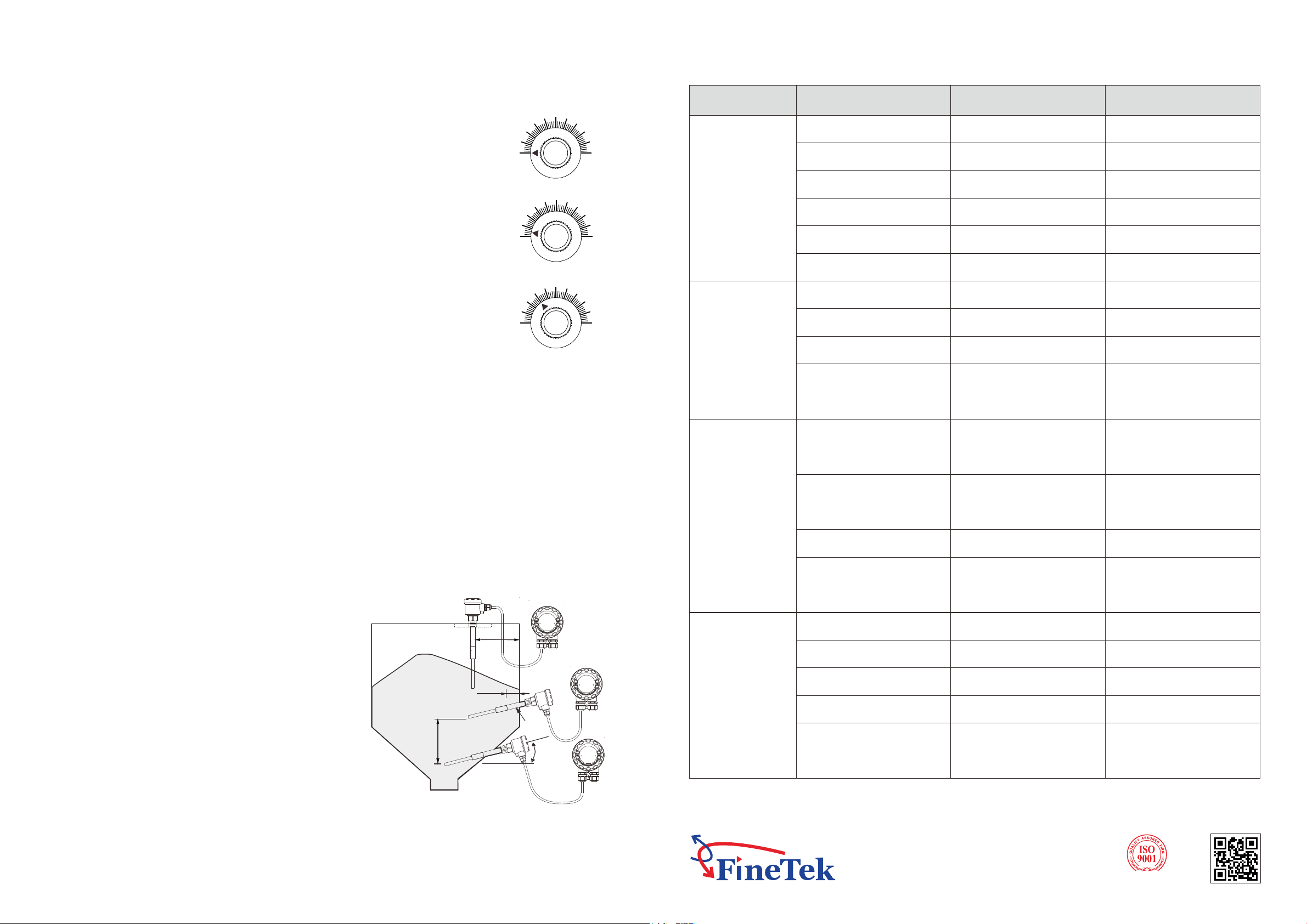
3. Side mounting angle: roughly 20 degrees.
1. Top mounted: Minimum distance should be 300mm
between the probe and wall.
2. The insulated probe should protrude at least 30mm
from the tank wall.
4. The conduit and wiring should face downward.
INSTALLATION (SEE THE SKETCH BELOW)
300mm
30mm
No induction body
20°
300mm
MAINTENANCE & TROUBLE SHOOTING
Circumstance
Level up & down
but switch / relay
no response
Level up & down
but switch on/off
continuously
non-stop or relay
can't be reset
Seal ring aged & failed
Cable entry is not
firmly locked
Cable entry does
not face down
Cable wire does not
connected downward
Diameter of cable wire
does not fit
Enclosure is loose
Seal ring aged
Cable entry is not
firmly locked
Cable entry faces up
Cable wire is connected
upward
Cable wire is loose
Lock the enclosure firmly
Replace seal ring
Lock the cable entry firmly
Turn the cable
entry & face down
Connect the cable
downward
Replace cable with
diameter 8mm~ 10mmf f
Circuit damaged by EMI
Probe contacts
with tank wall
Circuit damaged by EMI
Dielectric constant
is over limit
Probe contacts
with tank wall
Probe with water or dew
Dry powder or high
speed friction
Rough and fine adjustment
remain active
Replace probe with coating
Re-install and avoid
grounding
Replace with
anti-static model
Please contact your
distributor or FineTek directly
Process connection
is not firmly locked
Short-circuit due to aging
Abnormal of supply voltage
Loose structure due
to vibration
Loose screw bolt
Loose thread
Idle loop, resistance
abnormal
Supply voltage over limit
Obvious vibration
environment Replace with remote model
Restore power supply
Revise external layout
Lock thread or flange firmly
Lock screw bolt firmly
CALIBRATION (ROTARY KNOB)
H
90
80
70
30
60
50
40
20
10
L
H
90
80
70
30
60
50
40
20
10
L
H
90
80
70
30
60
50
40
20
10
L
Fig 2
Fig 3
Fig 4
(3) To increase the delay time, use a screwdriver to turn the "delay" trimmer clockwise. To decrease the delay time,
turn the "delay" trimmer counterclockwise.
(1) When delay time is "0" second, the LED and the relay signals will be activated simultaneously. The user can set
the delay according to his or her requirements.
(2) After delay set-up, the circuit functions as following: when LED of switch is on after time set-up, relay functions or
NPN signal outputs.
DELAY ADJUSTMENT
4. Turn the knob clockwise from H position to 90% position about 1/2 circle (95% position)
until LED indicator shut off (Figure 3). Then, Initial calibration is complete. After that,
please continue to next step "SENSITIVITY ADJUSTMENT".
1. After installation with power supply, make sure no material within 300 mm around the
probe.
3. Record the turning angle from "Indicator" sign lights up status to turn off status, then reset
"SENSITIVITY ADJ" by turning the knob counterclockwise back for half of the recorded
turning angle.
2. Turn the "SENSITIVITY" to the "H" position (Figure 2).
SENSITIVITY ADJUSTMENT
INITIAL CALIBRATION
1. Make sure the "Indicator" sign does not light up, when the medium does not contact with
the probe, and vice versa, when the medium contacts or covers the probe, then the
"Indicator" sign lights up.
3. Using flat-head screwdriver to turn "Coarse" clockwisely for adjustment until LED indicator
is on.
2. Gradually, adjust the capacitance value (turn the knob clockwise to the "L" direction) until
"Indicator" light turns off.
4. Based on the previous experience, 70% (Figure 4) adjustment position can be used to
most of mediums (Need to do INITIAL CALIBRATION first).
This manual suits for next models
3
Other FineTek Switch manuals


