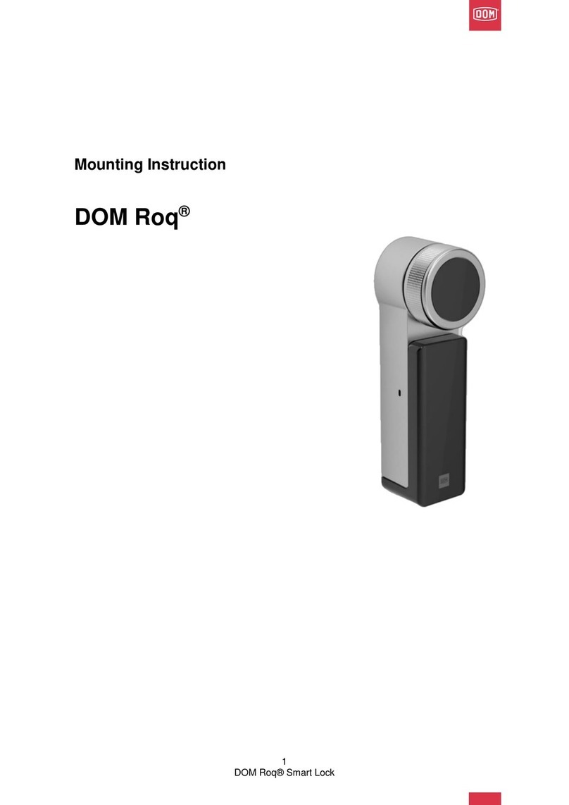
DOM ENIQ Guardian User manual

-Guardian & Guardian S

2
CONTENTS
SCOPE OF SUPPLY 3
PRODUCT DESCRIPTION 5
FOR YOUR OWN SAFETY 5
IMPORTANT INFORMATION 6
REQUIRED TOOLS 7
DOOR PREPARATION 8
Drilled holes for Guardian and Guardian S
for installation of outer tting and
inner tting on both sides 8
Drilled holes for Guardian outer tting or
inner tting, one-sided installation 9
INSTALLATION 10
Installation of Guardian 11
Installation of Guardian S 13
Installation of Guardian outer tting 14
Installation of Guardian inner tting 17
OPTIONAL AIDS AND CUSTOMISED VERSIONS 17
Drilling template for Guardian
Germany model (recommended): 17
Renovation plate 19
Symmetrical handle lock 20
Asymmetrical handle lock 22
PUTTING INTO OPERATION 24
OPERATION 25
Acknowledgement of terminations 25
Opening 26
Setting the coupling duration 26
Creating locking or programming media 27
Deleting locking or programming media 28
Deleting all locking or programming media 29
PROGRAMMING AND MANAGEMENT
WITH SOFTWARE 30
MAINTENANCE 31
BATTERY REPLACEMENT 32
Guardian battery replacement 32
Guardian S battery replacement 33
REMOVAL 35
Removal of the Guardian 35
Removal of the Guardian S 35
Removal of the Guardian outer tting 36
Removal of the Guardian inner tting 37
Removal of the Guardian handle 37
STORAGE/CARE 38
DISPOSAL 38
TECHNICAL DATA 38
WARRANTY 38

3
SCOPE OF SUPPLY
Depending on the order:
1) 2x screws M6
2) 1x screw M5
3) Cover and base plate on the inside with long
inner handle and threaded pin
4) Square
5) Sleeve if required
6) Base plate with threaded sleeves, slide,
coupling module, U-prole with electronics tted
and outer cover
7) Short inner handle with threaded pin
8) Battery
9) Battery compartment
10) 2x screws for battery compartment
GUARDIAN
Fig. 1: Guardian
1) 2x screws M6 short
2) 1x screw M6 long (battery compartment)
3) Inner tting with handle
4) Square
5) Sleeve if required
6) Outer tting with handle
7) Battery
8) Battery compartment
9) Sealing mat (not shown)
GUARDIAN S
Fig. 2: Guardian-S
Please note! All parts of the set can also be purchased individually.

4
1) Square
2) Sleeve
3) Base plate with threaded sleeves, slide,
coupling module, U-prole with electronics tted
and outer cover
4) Short inner handle with threaded pin
5) Battery
6) Battery compartment
7) 4x wood or countersunk screws M5
8) 2x screws for battery compartment
GUARDIAN OUTER FITTING
Fig. 3: Outer tting
1) 3x wood or countersunk screws M5
2) Cover and base plate on the inside with
long inner handle and threaded pin
GUARDIAN INNER FITTING
Fig. 4: Inner tting
OPTIONALLY AVAILABLE:
GUARDIAN STARTER SET COMPRISING:
• Master card
• Programming card
SET OF INSTALLATION TOOLS COMPRISING:
• Guardian drilling template
• Handle removal tool
RENOVATION PLATE

5
PRODUCT DESCRIPTION
All DOM access control components and thus also the Guardian leave the factory in a neutral state. They are only “initialised” i.e.
assigned to a master card shortly before installation. From this moment onwards, programming can only be performed on the
terminal device from this master card or from a programming card authorised with this master card. Alternatively changes can be
made via ENiQ Access Management for ENiQ systems and the ELS soware or ELSmobile soware for ELS systems. Therefore, the
owner of the master card exclusively decides on assignments and the allocation of authorisations. As an alternative, authorisations
can be stored on the transponders.
With the Guardian, DOM Sicherheitstechnik has accommodated all the electronic features in a single tting. The reading unit,
functional parts, mechatronics and the battery compartment are all located in the outer tting. This means the Guardian can be
installed on one side on the outside.
Alternatively, the Guardian can be installed with inner plate.
FOR YOUR OWN SAFETY
Always observe the notes and safety instructions.
Some sections of these installation instructions are highlighted by pictograms. Memorise these pictograms and their meanings:
Please note! This sign gives you useful information about installation or operation.
Caution! This sign marks a danger note or indicates an action that may cause damage to the Guardian or
other objects.

6
IMPORTANT INFORMATION
Caution! Material damage due to improper storage. If you store the Guardian for an extended period prior
to installation, store all the components in their original packaging in a dry, dust-free location at room
temperature (see also chapter Storage/Care).
Caution! Locking media do not belong in the hands of small children. Small parts may be swallowed.
Caution! Damage due to improper use.
Never throw or drop the Guardian. Never use force during installation.
Caution! Damage due to improper installation and operation. Read these instructions completely and
carefully prior to installation and commissioning. Follow the instructions step by step. The manufacturer
assumes no liability for damage resulting from improper installation or operation.
Caution! The Guardian must not be used in potentially explosive atmospheres.
Please note! Incorrect installation of the Guardian prevents the required locking function.
Caution! In the event of electrostatic discharge (sparks or breakdown), electronic components may be
destroyed. For this reason, avoid electrostatic charges prior to the installation/removal of the electronic
components or touch a conductive, grounded object (e.g. water pipe, heating) beforehand to remove
electrostatic charge from your body. Never touch the electronics components with your ngers.
Caution! The Guardian must not be oiled or greased.
Caution! Always store the Guardian a suitable distance away from the master card in order to avoid
unintentional initialisation.

7
REQUIRED TOOLS
For proper installation, the following tools are required:
(not included in the scope of supply)
Ruler or suitable measuring instrument
Hexagon socket key (Allen key): 2 mm, 3 mm.
Slot-head screwdriver
Pointed pliers
Guardian drilling template (recommended, optionally available)
Depending on the installation method:
Guardian:
Torx screwdriver (Torx T25)
Drills: 8 mm, 10 mm.
Guardian-S:
Cross-slot screwdriver (PH2)
Drills: 8 mm, 10 mm, 16 mm
Guardian outside on wooden door:
Cross-slot screwdriver (PH2)
Torx screwdrivers (Torx T10, T20)
Drill: 3 mm
Guardian outside with threaded inserts:
Cross-slot screwdriver (PH2)
Torx screwdrivers (Torx T10, T25)
Drills: (depending on the threaded inserts, usually 7 mm for M5 rivet-down nuts) Countersink Ø10 or larger
Guardian inside on wooden door:
Torx screwdriver (Torx T20)
Drill: 3 mm
Guardian inside with threaded inserts:
Drills: (depending on the threaded inserts, usually 7 mm for M5 rivet-down nuts) Countersink Ø10 or larger

8
DOOR PREPARATION
Caution! The Guardian can be screwed on doors with a thickness from 34 mm to 114 mm and a distance
between handle and cylinder from 55 mm to 94 mm (see Technical data).
Caution! We recommend use of the Guardian drilling template which you can purchase through
DOM Sicherheitstechnik. (see 17)
Caution! The Guardian S can be screwed on doors with a thickness from 39 mm to 83 mm and a distance
between handle and cylinder from 70 mm to 94 mm (see Technical data).
The door preparation procedure varies depending on whether you use the Guardian drilling template or wish to equip a door with
or without cylinder hole. The door must be prepared in compliance with the tting centre distances.
The screwing distances are dened to the centre point of the square/lock follower (handle rotation axis / handle support).
To achieve greater precision, drill from both sides.
Remove the lock if necessary.
Hole spacing:
Screw attachment Germany model:
B = 75.5 mm
C = 134.5 mm
Screw attachment France model:
B = 65 mm
C = 130 mm
Diameters:
Top = Ø10 mm
Centre = Ø8 mm
Bottom = Ø10 mm
Guardian S
Enlarge outer holes
Ø16mm and 10 mm deep
DRILLED HOLES FOR GUARDIAN AND GUARDIAN S FOR INSTALLATION OF OUTER FITTING AND INNER FITTING ON BOTH SIDES
Fig. 5: Drilled holes installation on both sides
The hole spacing depends on the version: Germany or France model.
Both the Guardian and the Guardian S are xed at three points. Above the handle nut (dimension “B”); in the centre below the
handle nut (21.5 mm) and below the cylinder hole (dimension “C”).
1. Use a ruler or other measuring instrument to mark the drilling points from both sides of the door. Make sure that the points form a
straight vertical line.
2. Remove the lock.
3. For Guardian S only: Drill all 3 points from the outside using the 16 mm drill to a depth of approx. 10 mm.
Then continue with point 4.
4. Drill into the central point from both sides using the 8 mm drill until you reach the hole for the lockcase.
5. Then drill into the upper and lower point from the outside using the 10 mm drill until about the centre of the door.
6. Now drill into the upper and lower point from the inside using the 10 mm drill until you reach the opposite drilled hole.
7. Remove the wood waste chips

9
Hole spacing outer tting:
82 mm from the handle hole upwards (two holes at the top)
118 mm from the handle hole downwards (two holes at the
bottom) 20 mm space vertically between the two holes
Hole spacing inner tting:
75.5 mm top
21.5 mm centre
134.5 mm bottom
Diameters:
Wood screws:
E = Ø3 mm
Rivet-down nuts:
E = Ø7 mm (for standard M5 rivet-down nuts)
DRILLED HOLES FOR GUARDIAN OUTER FITTING OR INNER FITTING, ONE-SIDED INSTALLATION
Fig. 6: Drilled holes installation on one side
The Guardian outer tting or inner tting is installed directly on the door either using the wood screws (included in the scope
of supply), or M5 screws (included in the scope of supply) and rivet-down nuts with countersunk head (NOT included in the scope
of supply) for metal doors.
The Guardian outer tting is installed using four screws: two at the top and two at the bottom. The upper (82 mm to the handle
hole) and lower screws (118 mm to the handle hole) are 20 mm away from each other, arranged symmetrically around the centre
of the tting.
Wooden door:
1. Use a ruler or other measuring instrument to mark the drilling points from the outside of the door.
2. Drill all the points using the 3 mm drill to a depth of around 20 mm.
3. Remove the wood waste chips
Metal door:
1. Use a ruler or other measuring instrument to mark the drilling points from the outside of the door.
2. Drill all the points using a 7 mm drill (or a drill with a diameter suitable for the threaded inserts).
3. Remove the metal swarf
4. Fit the threaded inserts rmly in place.
The Guardian inner tting is xed in place at three points. Above the handle nut (75.5 mm); in the centre directly under the
handle nut (21.5 mm) and under the cylinder hole (134.5 mm).
1. Use a ruler or other measuring instrument to mark the drilling points from the inside of the door. Make sure that the points
form a straight vertical line.
2. Drill all the points using the 3 mm drill to a depth of around 17 mm.
3. Remove the wood waste chips
Metal door:
1. Use a ruler or other measuring instrument to mark the drilling points from the inside of the door.
2. Drill all the points using a 7 mm drill (or a drill with a diameter suitable for the threaded inserts).
3. Remove the metal swarf
4. Fit the threaded inserts (not included in the scope of supply) rmly in place.
Inner Outer

10
INSTALLATION
Caution! Before the Guardian is installed, you must check to ensure the lock is working properly. The lock
must be rmly in place in its nal installation position.
Caution! If you have ordered a special version of the Guardian or Guardian S, read through the suitable
sections in the Special versions chapter rst (see 17) before you continue.
Caution! Material damage can be caused by the excessive tightening of screw ttings.
Caution! Before installation, make sure that the Guardian handle lock is inserted in accordance with your
installation situation. We recommend inserting the handle lock in the neutral position. (see 20)
Caution! If the threaded pin / set screw on the outer handle is tightened before being screwed to the inner
plate, increased axial pressure may be applied to the coupling mechanism. This leads to stiness within the
system. For this reason it is important that the threaded pin / set screw on the outer handle is not tightened
until the end. This applies to all installation variants.
Please note! The handles are clicked into place with the aid of the easyx attachment and are thus mounted
permanently rotatable. A description of the removal process can be found in the Removal chapter. (see 37)
Please note! The inside handle and outside handle have dierent lengths.
Please note! The following illustrations showing installation show installation without renovation plate. The-
se are simply put underneath if necessary. (see 20)
Please note! If you use the square in the coupling module, you will usually have to insert an adapter sleeve,
depending on the installation situation (lock variant):
• 9.0 mm lockcase nut (re and panic doors): no adapter sleeve necessary – the coupling module nut and
the square are both 9.0 mm.
• 8.0 mm lockcase nut (interior doors): adapter sleeve from 8 mm square to 9 mm coupling module nut
• 8.5 mm lockcase nut: adapter sleeve from 8.5 mm square to 9 mm coupling module nut
• 10 mm lockcase nut (exterior doors): adapter sleeve 9 mm square to 10 mm in lock follower (secure
against slipping)
Proceed according to the sequence described and observe the notes and gures.

11
INSTALLATION OF GUARDIAN
Follow the steps below:
Please note! Always install the Guardian with the door open so that you do not lock yourself out.
Please note! Always pay attention to the
position of the set screw for fastening the
square. It must be located on the top side
(12 o‘clock position) of the coupling module.
1. Insert the square, with adapter sleeve if appropriate,
into the coupling module: make sure you align the
eccentric drilled hole on the square to the threaded pin /
set screw of the inner handle.
2. Secure the square using the threaded pin / set screw.
Fig. 7: Inserting the square
3. Set the assembled unit on the prepared door leaf.
Fig. 8: Positioning the unit
Caution! Avoid deforming the door leaf during
connection of the inner base plate with the
positioned outer tting.
4. Align the base plate on the inside in such a way that
the edges for locking the cover in place face away from
the door leaf.
5. Connect the inner base plate to the assembled outer
tting using the three door through screws, taking the
door leaf structure into account: watch the screw
length.
Fig. 9: Inner base plate
Please note! Before you click the outer door handle into the easyx attachment, check smooth movement
and coupling function. For this, you require an authorised transponder which you have to create in accordance
with the description in the Operation chapter.

12
Caution! If the unit does not work perfectly, you will have to remove it. During removal make sure you do not
damage the reading module. (see 35)
6. Set the (short) outer handle onto the square, without
clicking the handle into the easyx attachment.
7. Present the authorised transponder.
8. Check smooth movement and coupling function.
9. If everything is working properly, click the handle into
place, but do not secure it with the threaded pin yet.
Fig. 10: Outer handle
10. Push the inner cover over the square but do not press
it into place yet.
11. Set the (long) inner handle onto the square and click it
into the easyx attachment.
12. Check smooth movement.
13. Following a successful function test, tighten the inner
base plate rmly.
14. Then press the inner handle rmly into place and
secure it on the outside with the threaded pin.
Fig. 11: Fixing the handle
Please note! Keep the original packaging so that you can store the Guardian safely at any time.

13
INSTALLATION OF GUARDIAN S
Follow the steps below:
Please note! It is urgent that you pay attention
to the position of the threaded pin / set screw
for fastening the square. It must be located
on the top side (12 o‘clock position) of the
coupling module.
1. Insert the square, with adapter sleeve if appropriate,
in the coupling module: make sure you align the
eccentric drilled hole on the square to the threaded pin /
set screw of the inner handle.
2. Secure the square using the threaded pin. (hexagon
socket 2 mm)
Fig. 12: Inserting the square
Please note! Always install the Guardian® S with the door open so that you do not lock yourself out.
3. Apply the sealing mat
Please note! Make absolutely sure that the
sealing mat is correctly applied during the
installation of the Guardian S.
Please note! Make sure that the seal in the
cylinder hole is not damaged during the later
assembly of a prole cylinder.
Fig. 13: Applying the sealing mat
4. Place the outer tting on the prepared door leaf.
Fig. 14: Positioning the outer tting

14
Please note! Keep the original packaging so that you can store the Guardian S safely at any time.
5. Place the inner tting onto the door leaf and x it in
place with the 3 screws.
Please note! The longer of the three screws is
inserted into the lowest hole and xes the
battery compartment in addition. To do this,
push the battery compartment into the outer
tting and hold it tight. Screw the bottom
and longest screw in on the inside. Then
screw the top and middle screws into the
holes provided.
6. Then secure the inner handle using the threaded pin.
Fig. 15: Fixing the inner tting
INSTALLATION OF GUARDIAN OUTER FITTING
Follow the steps below:
Please note! If you use the square in the coupling module, you will usually have to insert an adapter sleeve,
depending on the installation situation (lock variant):
• 9.0 mm lockcase nut (re and panic doors): no adapter sleeve necessary – the coupling module nut and
the square are both 9.0 mm.
• 8.0 mm lockcase nut (interior doors): adapter sleeve from 8 mm square to 9 mm coupling module nut
• 8.5 mm lockcase nut: adapter sleeve from 8.5 mm square to 9 mm coupling module nut
• 10 mm lockcase nut (exterior doors): adapter sleeve 9 mm square to 10 mm in lock follower (secure against
slipping)
Please note! Always pay attention to the
position of the set screw for fastening the
square. It must be located on the top side
(12 o‘clock position) of the coupling module.
1. Insert the square, with adapter sleeve if appropriate,
in the coupling module: make sure you align the
eccentric drilled hole to the threaded pin / set screw of
the inner handle.
2. Secure the square using the threaded pin / set screw
(hexagon socket 2 mm).
Fig. 16: Inserting the square

15
3. Remove the battery compartment and battery as
described in the Battery replacement chapter. (see 32,
steps 1 to 4)
4. Use a Torx spanner (Torx T10) to loosen the cover and
li it slightly.
5. Clip the cover out at the top of the U-prole.
Fig. 17: Removing the cover
6. Undo the attachment screws on the U-prole and
remove both screws and connecting sleeves.
Please note! Hold the battery compartment
underneath until the screws are rmly in place
in order to avoid parts falling. Use adhesive
tape to help if necessary.
Fig. 18: Removing attachment screws and connecting sleeves
Please note! Always install the Guardian with the door open so that you do not lock yourself out.
7. Set the prepared unit on the prepared door leaf.
8. Use the 4 attachment screws to x the unit in place
in accordance with your installation situation and
screw on: the Guardian is provided with the following
screws for attachment of the unit:
• chipboard screws 4.5x40 (Torx T20) for solid wooden
leaf doors
• M5x30 A2 ISO 7991 for metal doors or tubular frame
doors (threaded inserts)
Fig. 19: Attaching the unit

16
9. Clip the cover in at the top of the U-prole.
10. Hook the tab on the outer cover in between the screw
and the U-prole and press into place.
11. Secure the cover using the attachment screw and
tighten using the Torx spanner (Torx T10).
12. Remove the battery and battery compartment as
described in the Battery replacement chapter.
(see 32, steps 6 to 9)
Fig. 20: Setting the outer cover in place
Please note! Before you click the outer door handle into the easyx attachment, check smooth movement
and coupling function. For this, you require an authorised transponder or the new ENiQ building locking card
(ENiQ only, Q1 2017), which you have to create according to the description in the Operation chapter.
13. Set the handle onto the square, without clicking the
handle into the easyx attachment.
14. Present the authorised transponder.
15. Check smooth movement and coupling function.
16. Aer a successful functional test, click the handle into
place and secure using the threaded pin.
Fig. 21: Attaching the handle
Caution! If the unit does not work perfectly, you will have to remove it. During removal make sure you do not
damage the reading module (see the Removal chapter).
Please note! Keep the original packaging so that you can store the Guardian safely at any time

17
INSTALLATION OF GUARDIAN INNER FITTING
Follow the steps below:
1. Set the handle onto the square.
2. Hold the cover horizontally so that the screwing points
are visible.
3. Tighten the screws.
4. Check function.
5. Snap the cover into place.
6. Secure the handle using the threaded pin.
Fig. 22: Inner base plate
OPTIONAL AIDS AND CUSTOMISED VERSIONS
Caution! The Guardian drill template must be in proper working condition. Be sure to replace any worn drill
templates. Always align the drill template very exactly in order to prevent damage to the door.
The Guardian drill template is designed for locks (PC, RC, PRC) with a distance of 55 mm to 94 mm between the handle and the
cylinder.
You can use the Guardian drill template to spot-drill the holes for one-sided and two-sided installation directly through the drilling
template into the door leaf without removing the drilling template rst.
DRILLING TEMPLATE FOR GUARDIAN GERMANY MODEL (RECOMMENDED):
Depending on the distance between the centre of the
lock follower and the centre of the keyhole of the lock
cylinder, you must screw in the bolt (diameter 10 mm, see
illustration) at dierent positions to x it in the cylinder hole.
A: 55 mm
B: 70 – 78 mm
C: 88 – 94 mm
D: You can determine the bolt diameter for the lock
follower by measuring the square or by inserting the bolt
into the lock follower (7; 8; 8,5; 9 or 10 mm).
Fig. 23: Drilling template bolts

18
DRILLED HOLES FOR GUARDIAN AND GUARDIAN S:
For installation on both sides, you must use the three inner
drilled holes. A through hole must be drilled.
Drilling diameter top/bottom = 10 mm
Drilling diameter centre = 8 mm
With the Guardian S all three drilled holes must have been
spot-drilled to 10 mm depth rst using a 16 mm drill. The
8 mm or 10 mm drill is then used to drill the through hole.
Recommendation: always drill on both sides to ensure the
exact positioning of the ttings.
Fig. 24: Drilling template for both sides
Follow the steps below:
1. Screw the bolt for the square opening into the drill template.
2. If there is a PC hole present, screw in the bolt for the PC hole into the drill template according to the distance between the
centre of the lock follower and the centre of the keyhole in the lock cylinder.
3. Set the drill template in place.
4. If there is no PC hole present, align the drill template by hand so that it is parallel to the edge of the door and x it in place.
5. Fix the drill template so that it does not move.
6. Spot-drill the holes.
7. If necessary, remove the lock or repeat the procedure to spot-drill the second side.
8. Remove the drill template and the lock.
Caution! Before you drill the holes into the door, make sure you will not drill through the door. Set the drill so
that the drill bit does not drill through the door and damage the door leaf on the inside of the door or the lock.
If necessary, use a depth stop or remove the lock. Always use suitable drill bits (wood, metal).
When rivet-down nuts are used, the door leaf may have to be countersunk to prevent the collar protracting. For this
reason, we recommend the use of blind rivet nuts with a countersunk head.
The manufacturer is not liable for any damage caused by improper installation.
9. Drill the holes at right angles on both sides if required.
10. Carefully remove drilling chips.
DRILLED HOLES FOR GUARDIAN OUTER FITTING
For installation on one side, you must use the four outer
drilled holes. Make sure threads or attachment points are
available at the attachment points.
The following screws are included for the one-sided attach-
ment of the unit: M5x30 (hexagon socket) for tubular frame
doors with rivet-down nuts 4.5x40 (T20) for solid wooden
leaf doors
Fig. 25: Drilling template for the outside

19
DRILLED HOLES FOR GUARDIAN INNER FITTING
For installation on both sides, you must use the three inner
drilled holes. A through hole must be drilled.
Drilling diameter top/bottom = 10 mm
Drilling diameter centre = 8 mm
Recommendation: always drill on both sides to ensure the
exact positioning of the ttings.
Fig. 26: Drilling template for the inside
Follow the steps below:
1. Screw the bolt for the square opening into the drill template.
2. If there is a PC hole present, screw in the bolt for the PC hole into the drill template according to the distance between
the centre of the lock follower and the centre of the keyhole in the lock cylinder.
3. Set the drill template in place.
4. If there is no PC hole present, align the drill template by hand so that it is parallel to the edge of the door and x it in place.
5. Fix the drill template so that it does not move.
6. Spot-drill the holes.
7. If necessary, remove the lock or repeat the procedure to spot-drill the second side.
8. Remove the drill template and the lock.
Caution! Before you drill the holes into the door, make sure you will not drill through the door. Set the drill so
that the drill bit does not drill through the door and damage the door leaf on the inside of the door or the lock.
If necessary, use a depth stop or remove the lock. Always use suitable drill bits (wood, metal).
When rivet-down nuts are used, the door leaf may have to be countersunk to prevent the collar protracting. For this
reason, we recommend the use of blind rivet nuts with a countersunk head.
The manufacturer is not liable for any damage caused by improper installation.
9. Drill the holes at right angles on both sides if required.
10. Carefully remove drilling chips.
RENOVATION PLATE
Renovation plates can only be used with the Guardian.
The thickness of the plates (3 mm each) must be added to the thickness of the door when placing your order.
Before the outer tting is set in place on the door, position the renovation plate between the door and the outer tting. Then
insert the outer tting into the holes. The same applies for positioning of the renovation plate on the inside of the door. Please
note the length of screws you require when placing your order.

20
SYMMETRICAL HANDLE LOCK
Depending on the use of the handle lock, you can limit or permit the upward operation angle of the handle.
Caution! Upon delivery, the handle lock is inserted in the module setting neutral (N).
Please note! Depending on the direction the handles are facing, you will have to align the handle lock in dierent
ways. The arrow on the handle lock is point towards the module setting.
Fig. 27: Module setting neutral
Caution! If you have inserted the handle
locking on the module setting le (L) or right
(R) you must not subject the handle to more
than 10 Nm force against the operating
direction (case A).
Otherwise the coupling module will be
damaged.
There is no risk of this happening with module
setting neutral (N) (case B).
Fig. 28: Removing the handle lock
1. Insert a slot-head screwdriver into the recesses of the
slide.
2. Open the slide far enough to be able to remove the
handle lock using an ancillary tool (e.g. pointed pliers).
Caution! Aer you have inserted the handle
lock again, always close the slide again in
order to avoid destruction of the coupling
module.
Other manuals for ENIQ Guardian
1
This manual suits for next models
5
Table of contents
Other DOM Lock manuals
Popular Lock manuals by other brands

Visionis
Visionis VIS-ML600LED-BL Installation & user guide

Burg Wächter
Burg Wächter secuENTRY easy ENTRY 7601 PIN Initial setup

Intelligent Biometric Controls
Intelligent Biometric Controls 1TouchIQ2 Series user guide

Stock Loks
Stock Loks C8717 instruction sheet

Allsteel
Allsteel Align Keypad Digital Lock user guide

Trinity
Trinity Alpha 70K TMA 7590 Product Description and Assembly Manual