DOM WENS 800 Series User manual

WENS 800 Series
Operator’s Manual
DOM
TM
Hand-held Digital Oscilloscope Meter

Digital Oscilloscope Meter

2
Table of Contents Table of Contents
Hand-held Digital Oscilloscope Meter 3
1. Notes for Safe Operation 4
1 - 1. Prevention of fire or injury 4
1 - 2. Safety Terms and Symbols 6
1 - 3. Preventing electro-static discharge 7
2. Main Product Items and Layout 8
2 - 1. Main product items and performance features 8
2 - 2. Product configuration 9
3. Initial Setting Operation before use 10
3 - 1. Function Confirmation 11
3 - 2. Probe Adjustment 12
3 - 3. Adjusting the time and date of the oscilloscope 13
3 - 4. Adjusting Auto Power-off 13
3 - 5. Adjusting Contrast 13
3 - 6. Selecting Language 14
3 - 7. System Information 14
3 - 8. Mute 14
4. Front Layout Summary 15
4 - 1. Front Layout 15
4 - 2. Keys 16
5. Display Layout Summary 19
6. Menu Operation Summary(OSCILLOSCOPE) 20
6 - 1. Display(Waveform, Contrast, Graticule, Persistence) 20
6 - 2. CH A, CH B 23
6 - 3. TRIGGER 28
6 - 4. Trigger Mode 34
6 - 5. TIME 34
6 - 6. MEASURE 35
6 - 7. CURSOR 37
6 - 8. Acquire(Normal, Average, Peak) 40
6 - 9. MATH(DWM, FFT) 44
7. MULTIMETER 46
7 - 1. AC and DC VOLTAGE(mV, V) measurement 46
7 - 2. Resistance measurement 48
7 - 3. Diode test 49
7 - 4. Continuity check 50
7 - 5. Capacitance measurement 51
7 - 6. Current / Temperature(OC, OF)/RHumidty/pressure
measurement with exterior Adapter 51
8. ZOOM/SAVE 52
8 - 1.
ZOOM Function
52
8 - 2. SAVE Function 55
9. AUTO 64
10. DATA LOGGER 65
11. External Layout Summary 68
11 - 1. USB PC Communication 68
11 - 2. USB Flash Memory 69
11 - 3. AC, DC Power 70
11 - 4. Tilt Stand 70
11 - 5. Battery 71
12. Product Standards and Specifications 72
13. Revisions and Remarks 80
Table of Contents
For the safe and effective operation of unit, please read
this manual carefully before using the unit.
Position
Position
Position

1. Notes for Safe Operation 1. Notes for Safe Operation
1. Notes for Safe Operation
1 - 1. Prevention of fire or injury
Use a proper AC Power Adapter. or Test Leads
- Only use a Power Adapter or Test Leads suplied with the instrument.
Connect and Disconnect Properly
- Connect the probe or Test Leads output to the measuring device before
connecting to the active circuit in testing. Before disconnecting the probe or
Test Leads from the measuring device, first disconnect Probe or Test Lead
from active circuit in testing.
Observe all terminal ratings
- In order to prevent fire or risk of electrical shock, observe all ratings and
markings of the unit. Before connecting to the unit, refer to the operator°Øs
manual for detailed information on ratings.
Max Input Voltages
Max Floating Voltage
Replace the battery properly
- Replace the battery supplied by manufacturer.
- Do not connect the ground wire to voltages higher than 42V Peak(30Vrms)
from earth groud.
Do not use exposed metal BNC or Banana plug connectors.
- Use only insulated voltage probes, test leads and adapters supplied with the
instrument.
- Do not apply any voltage when measuring OHM(Resistance), or Capacitance
of Meter mode.
Do not operate the unit without its cover.
- Do not operate this unit with its cover properly.
Do not expose the circuits.
- Do not touch any exposed connecting parts or components while power is
being supplied.
Do not operate the unit if it does not operate properly.
- If you suspect there is damage to this product, have it inspected by qualified
service personnel.
Do not operate this unit in wet or damp environments.
Do not operate this unit in any environment in a risk of explosion.
Maintain the surface of the unit in a clean and dry state.
Provide proper air ventilation.
WARNING. USE EXTREME CAUTION IN THE USE OF THIS INSTRUMENT
Improper use of this device can result in injury or death.
Follow all safeguards suggested in this manual . In addition to the normal
safety precautions used in working with electrical circuits.
DO NOT service this device, if you are not qualified to do so.
Scope Input.
- Input CH A and CH B direct(1:1 probe) 300V CATⅢ
Meter Input
- 600V CATⅢ
- 600V CATⅢ
- Voltage ratings are “working voltage” Vac-rms(50 - 60Hz) for AC sine
wave and Vdc for DC applications
4Hand-held Digital Oscilloscope Meter 5

1. Notes for Safe Operation 1. Notes for Safe Operation
1 - 2. Safety Terms and Symbols
Technical terms which appear in this manual are listed below.
Technical terms related to the unit.
- The following terms appear on the unit.
- DANGER indicates an injury hazard immediately accessible as you read the
marking.
- WARNING indicates an injury hazard not immediately accessible as you read
the marking.
- CAUTION indicates a hazard to property including the product.
Symbols related to the unit
- The following symbols appear on the unit.
1 - 3. Preventing electro-static discharge
Select a proper working location.
- When installing or removing sensitive equipment, do not use devices which
can or have the potential to discharge static electricity. Do not handle sensitive
equipment on floors or worktables which can discharge static electricity.
Handle components with care.
- Do not slide sensitive components on any surfaces. Do not allow them contact
with any exposed connector pins. Handle sensitive components to the
minimum extent possible.
Transport and store with caution.
- Transport and store in ESD preventive bag or container which protects
sensitive components from static electricity
Recycling the battery
- The battery(optional) must be properly recycled or disposed.
Danger
High Voltage Protective
Grounding
(Earth)Terminal
CAUTION
Refer to
Manual
Battery
Information
WARNING. Warning statements identify conditions or practices that could
result in injury or loss of life.
CAUTION. Electro-static discharge(ESD) can result in damage to the
oscilloscope components and accessories. To prevent ESD, observe the
following prevention guidelines when instructed to do so.
CAUTION. Do not connect USB Flash memory device and USB PC cable to
the Oscilloscope simultaneousely. In this case, operation will be stopped
and can resume when RESET
CAUTION. Caution statements identify conditions or practices that could
result in damage to this product or other property.
6Hand-held Digital Oscilloscope Meter 7

2. Main Product Items and Layout
B. Digital Multi Meter
- High Precision, Rugged Autoranging True RMS DMM
- 6000 Count with Analog Bargraph Display
- True RMS AC Volts/30kHz wide band
- Complete measurement ranges
DC Volts, AC Volts(RMS), Ohm, Capacitance, Diode, Continuity. (through
external adapter) : Currents, Temperature, %Relative Humidity, Pressure
2 - 2. Product configuration
A. Unit with Standard Accessories
- Instrument with Holster case 1set
- Passive Probe are varied on Bandwidth of the Osccilloscape CATⅢ300V
20Mhz(1:1):2PCS or CATⅢ600V 60Mhz(10:1) : 2PCS, or 100Mhz(10:1)
200Mhz(10:1):2pcs
- Test Leads(CATⅢ1000V) Black + Red 1 set
- PC Software set(USB Database & Flash Memory PC Flatform
Data base) 1CD
- AC Power Adapter and Internal Charger 1pc
- Operator’s Manual in CD or Hardcopy manual
B. Optional Accessories
- Internal Back Up Battery System & Battery Pack : 2PCS/Unit
- Internal USB FLASH MEMORY System & Port System
(Equipped Internally)
- Deluxe Carrying Bag
- Temp Adapter
- AC Current Adapter
2. Main Product Items and Layout
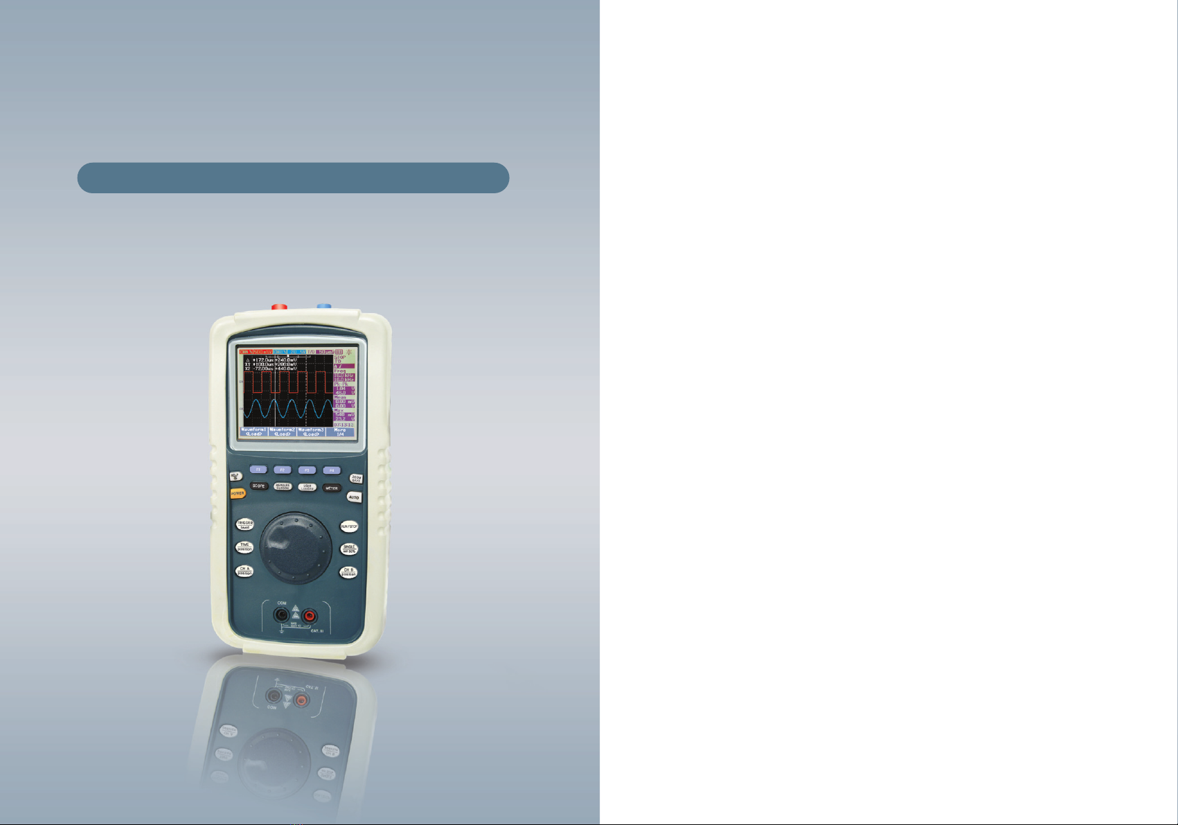
This instrument was designed to provide analysis of signals through its fast
signal acquisition ability through the Fast Data Acquisition Unit. Through a
variety of capture methods such as Average, Peak-Detect, along with its long
recording length, it enables the user to quickly and accurately acquire the signal
properties. In addition, it offers a more convenient working environment through
the use of basic interfaces including, USB storage device and USB PC
Communication.
2 - 1. Main product items and performance features
A. Oscilloscope
- 2 Channel, 20MHz(Model 820 ) 40MHz( Model 840) 60MHz( Model 860)
100MHz( Model 800x) or 200MHz( Model 800z)
- Maximum 200MS/s or 1GS/s Real sampling, 2.5GS/s or 5GS/s Equivalent
sampling
- Peak Detection for Glitch Acquisition
- Maximum 125K Long Record Length (Model 800, 840, 860), 10kbyte(Model
800x, 800z)
- Auto-set for quick waveform acquisition
- Improved Trigger Function(Edge)
- Saving of configuration settings and waveforms
- 22 auto measurement features
- Diverse Capture Modes(Sample, Peak-detect, Average)
- Dual Waveform Computation and FFT Spectrum Analysis(except model 820)
- Support for Portable Flash USB Storage Devices(option)
- Zoom function
- Persistence Intensity Display
- Large 3.8°» 320°ø240 Color LCD
- USB equipped as standard interfaces
8Hand-held Digital Oscilloscope Meter 9

3. Initial Setting Operation before use
3 - 1. Function Confirmation
Perform the following simple steps to verify that the oscilloscope is operating
properly
Connect the unit power adapter.
Press button longer
- Press key
- Press to enter “UTILITY”
- Select 3/4 menu page
- Press “Self Cal”
- Select “OK?”
Self-Cal needs approx 4minutes. Verify whether the tests are OK. To proceed
the test, disconnect any Connections on Input terminals (Oscilloscope probe.
Test Lead, USB Connector etc). Self-Cal performs with is the allowable
Conditions and circumstances.
3. Initial Setting Operation before use
For more effective operation, the instrument performs quick confirming of
functions and provides passive probe installation and adjustment, and setting of
time and date. This section explains the methods for quick confirmation on if the
instrument is powered on, if it is operating properly, adjusting the probe using
the internal adjusting signal, and setting the time and date
- All initialization/configuration steps must be performed when first using the
instrument.
- Basic Self Tests shall execute upon power on. Be sure not to connected with
any signal to the instrument during testing. The purpose of this test is to flag a
major system problem.
- Whenever attaching the passive probe(initially, for the first time) to the input
channel, the probe adjustment steps must be performed.
Self Calibration
10 Hand-held Digital Oscilloscope Meter 11

3. Initial Setting Operation before use
3 - 3. Adjusting the time and date of the oscilloscope
Follow the steps to adjust the time and date of the oscilloscope
Press the button
Press Utility(this step does not need in METER mode)
Press MORE to enter 2/4 page
Press the date and time input confirmation menu button to set
the date and time.
3 - 4. Adjusting Auto power off
“Auto power off” time can be selected by user.
A. press key
B. Press utility (this step does not need in METER mode) to select
1/4menu page
C. select 5 min, 10 min, 30 min, 1 hr, 2hr, 4hr or OFF by key
3 - 5. Adjusting Contrast
LCD brightness can be adjusted by user
(when Oscilloscope mode)
press key
Press to select Display
select contrast by key and adjust CONTRAST by Encoder switch.
(when METER MODE)
press key
Press to select 3/3 page
Press to select CONTRAST
Press to adjust CONTRAST by Encoder switch.
3. Initial Setting Operation before use
3 - 2. Probe Adjustment
Perform the adjustment function to match the probe to the input channel. This
function must be performed each time the passive probe is first attached to the
input channel.
A square waveform must appear on the screen.
Press key
Press key
Press key to select UTILITY
Press key to select 3/4 menu page. Set Oscilloscope Probe to 10X1
attenuation. Connect BNC of Oscilloscope Probe to Ch B Input Terminal
of Oscilloscope, attach Socket on the tip of Oscilloscope Probe and connect
to Ch A.
Press key to select Probe Cal. Square wave will come out from Ch A.
Then use Adjustment Capacitor on the Oscilloscope Probe.
After Probe Adjustment is properly finished as per below diagram (adjust
to PROPER COMPENSATION), press to Enter mode. 1KHz = Vpp
3V Square wave will be displayed on display.
Verify the shape of the wave appearing on the screen
OVER COMPENSATION UNDER COMPENSATION PROPER COMPENSATION
12 Hand-held Digital Oscilloscope Meter 13

4. Front Layout Summary3. Initial Setting Operation before use
3 - 6. Selecting Language
Language can be selected by user
A. press key
B. Press utility to Select 1/4 menu page(in Oscilloscope mode), 1/3
menu page(in METER mode)
C. select Language by key
3 - 7. System Information
Press key while in Oscilloscope mode
Press UTILITY
Press to select System Information in 3/4 menu page. Model,
Firmware, Self Cal status are displayed.
3 - 8. MUTE
Press key
Press Utility and select 4/4 menu page MUTE
Press to select MUTE ON or MUTE OFF
( MUTE ON does not sound when press the buttons. MUTE OFF sounds when
press Buttons)
4. Front Layout Summary
4 - 1. Front Layout
MULTIMETER INPUT
Volts Resistance, Capacitance,
Diode, Continuity, Aux(Temperature,
Currents, Humidity, Pressure)
CH A
320×240pixel
LCD Display with
Backlight
Contrast
Adjustment
HELP
AC Power Adapter
& Internal charger
POWER
CH B
OSCILLOSCOPE INPUT
USB(mini)PC
Communication
USB Flash
memory Host
Encoder S/W for easy
and Fast access
Software key
ZOOM/SAVE
AUTO
RUN/STOP
SINGLE/set to
50%
CH B and Position change
CH A and
Position change
Time and
Position change
Trigger and level change
(METER)
USER, Data Logger
Measure Cursor
SCOPE
14 Hand-held Digital Oscilloscope Meter 15

4. Front Layout Summary4. Front Layout Summary
4 - 2. Keys
Soft keys are located directly below the Liquid Crystal Display and perform
muliple operation as indicated on the Liquid Crystal Display and determined by
the function selected by the rotary switch.
menu contains many menu pages
Some functions will produce a sub-menu on the display for further selection
Operation of the menus and sub-menus is described in the appropriate operation
paragraph.
: Keys to select various Software Program.
: Power ON and OFF (press longer than 2 seconds)
: Display user guide ON Test procedure ON each measuring range
: Scope mode : Auto scale function
Meter mode : Select AUTO Range/Manual Range mode.
: Oscilloscope mode
: Digital multimeter mode
NOTE : Softwarekey has no EXIT
menu. When is in measurig, ENTER or EXIT
between software key menu should be done by
pressing the major key respectively.
Oscilloscope Measurement Cursor ; press longer than 2 seconds to enter
or exit the mode
USER
(Oscilloscope mode only) Display method, Acquire,MATH, Self-Cal,
Probe Cal,System Information,(Meter mode only) dBM selection
(Oscilloscope / Meter ) Auto Power Off, Language, USB, Time,
Contrast, MUTE On/OFF
LOGGER (Meter in AUTORANGING mode ) : Data Aquired in logging
by time. Recorder function. Press longer than 2 second to enter or exit
the mode
ZOOM : Enlarge Waveform to analyze the waveform precisely.
SAVE : Press longer than 2 seconds to enter or exit the mode
Temporary Hold(STOP) or Run ( go) the operation of Oscilloscope
Meter
Various TRIGGERING function
level : press longer than 2 seconds to enter the mode and change
various levels by Encoder Switch Press longer than 2 seconds to exit the
mode .
Various TIME function
position : Press longer than 2 seconds to enter the mode and change
waveform position by Encoder switch. Press longer than 2 seconds to
exit the mode.
DUAL Function Key
These Key has dual functions. upper
line functions Can be entered short
ress time. Lower line functions Can
be entered or exit only press longer
than 2 seconds.
Position Position
Position
NOTE
RUN/STOP
Position
16 Hand-held Digital Oscilloscope Meter 17

5. Display Layout Summary
Display Indicators Explanation
CH A, CH B, math waveform and trigger A,
B level, horizontal position, CH A, CH B
offset, volt/division, time/division and so on.
Analogue Bargraph, MIN, MAX,
AVG VOLT, DC and so on.
Main Display waveforms and indicators
Oscilloscope Meter
4. Front Layout Summary
Encoder is activated only in oscilloscope mode for adjustment of.
- Volts/div
- Position(Move A, Move B)
- Trigger Level
- Pulser Trigger Period/ Pattern Trigger Period
- Video Trigger Line
- Time/div
- Horizontal Position
- Zoom Window
- Zoom Time
- Measure Parameter Select
- SAVE
- Cursor Move
- Contrast
- Average Number Select
- Math Position
- Time Set
- Help menu page change
- dBM Resistance Selection
For Faster speed, push down ENCODER Switch to enter or exit from COARSE
mode( 25 times faster than Normal speed)
Single Shot mode
Set to 50% of Edge Trigger . press longer than 2 seconds to enter or
exit the mode
select CH A or CH B
change waveform position . press longer than 2 seconds to
enter the mode and change position by Encoder switch.Press
longer than 2 seconds to exit the mode
Position
Position
18 Hand-held Digital Oscilloscope Meter 19

6. Oscilloscope Function 6. Oscilloscope Function
6. Oscilloscope Function
6 - 1. DISPLAY
Clear Displaying reset the persistence display
Configures the display environment and method of display for acquired
waveform.
Waveform
Selects whether to display waveform points connected with a line or to
display dots only. In case dot, only 250 waveform data displayed.
Type vectors, Dot
DISPLAY Contrast 20~79
Graticule Full, Cross hair, Grid, Frame
Persistence OFF, Infinite
Clear Display Reset the persistence display
Top level menu Sub menu Mode
Displaying in linear mode, the high-low of square
waves will appear connected. In dot mode, the
high-low of square waves will appear separate.
Contrast
Adjust the screen contrast using ENCODER Switch.
Graticule
Adjusts the grid shape of the waveform display section
Select type of lines, Full(10×8 lines including grid), cross Hair(cross +
sharp lines) Grid(10×8 lines) or Frames(Outer Frame lines)
FULL CROSS HAIR
GRID FRAME
20 Hand-held Digital Oscilloscope Meter 21

6. Oscilloscope Function 6. Oscilloscope Function
6 - 2. CH A, CH B
This function allows changes the settings of the CH A(CH B) input signal. Press
to display the sub menu for configuration setting changes. By
using the software key corresponding to the item in
the sub menu, configuration settings can be changed.
On/Off On/Off
Coupling DC/AC
Position volts/div, position A
Probe 1X, 10X, 100X
Invert On/Off
Position to 0 Sets vertical position to 0V
Top level menu Sub menu Function
CH A(CH B)
MORE 1/2(page 1/2)
CH A(CH B)
MORE 2/2(page 2/2)
Position Position
Position Position
How to change position
1. For fast change, press
Key longer than 2 seconds and change
position by Encoder Switch.
2. Select on page 1/2 of CHA (CHB)
and change position by Encoder Switch
Position
Position
Persistence
In persistence mode, Channel and Math function are displayed Dimmer for
previous acquisition.
NORMAL MODE PERSISTENCE MODE
22 Hand-held Digital Oscilloscope Meter 23

6. Oscilloscope Function 6. Oscilloscope Function
Coupling (MORE 1/2 page 1/2)
Use this function to capture a specific area of waveform.
①①DC coupling
The input signal is directly connected to the amplifier which components can
be viewed. The symbol on the top line of the screen.
②②AC coupling
The input signal passes through the condenser and is connected to the
amplifier. Only the alternating current components of the input signal can be
viewed. The symbol on the top line of the screen.
③③Ground coupling
The input signal is split and the input signal entering the vertical amplifier is
grounded. The symbol will display on the top line of the screen.
AC coupling removes the waveform’s DC
component and displays the remaining
waveform only.
DC coupling
Ground coupling
Confirms channel’s vertical position
and the position of the ground coupling
signal are met.
AC coupling
On/Off (page 1/2)
Use this function to turn the CH A(CH B) waveform on or off. In the On state,
the vertical sensitivity and vertical position indication will display corresponding
to the position of CH A and CH B. In the Off state, these indicators will not
display.
Waveform off Waveform on
24 Hand-held Digital Oscilloscope Meter 25

6. Oscilloscope Function 6. Oscilloscope Function
Position to 0 (page 2/2)
Use this function to set the CH A(CH B) waveform offset to 0. This is a
convenient function to return to the original state after changing the offset(via
the ENCODER switch) to view the top and bottom of the waveform.
Press the F2 button once to locate
OFFSET at center of vertical Axis.
Waveform is located below beyond the
display of the screen.
Waveform position at lower area of screen Waveform position at center of vertical Axis
Probe
The probe must be set according the probe setting in order to adjust the scope
voltage unit to match the probe scale
- 1x : Select when using 1:1 probe or when directly inputting the signal to the
input terminal.
- 10x : Select when using a 10:1 probe.
- 100x : Select when using a 100:1 probe.
Position (page 1/2)
To set Vertical position by rotating ENCODER Switch.
Note. Long time use of the unit or use in an not recommended environment may
cause disagree of the channel’s vertical position and position of the ground
coupling signal. In this event, turn power off and On for automatic 0 setting.
Invert (page 1/2)
Use this function to display an inverted waveform(change positions of upper
waveform and lower waveform) Waveform voltage level will change based on
earth grounding level of waveform. For example +5V voltage will appear as -5V.
It is used when set INVERT of waveform characteristics of CH A/CH B
The waveform symbol changes.
+440mV changes to -440mV and
+80mV changes to -80mV.
After InversionBefore Inversion
26 Hand-held Digital Oscilloscope Meter 27

6 - 3. TRIGGER
Use this function to configure settings for the trigger and trigger type.
Set Trigger and Trigger type. For Trigger function, press key a short second.
For level change, press key longer than 2 seconds to enter the level mode of
Edge Trigger and change level by Encoder Switch.
Edge
Use to acquire the waveform from the rising and falling edge of the signal for
the trigger level. Setting value of Trigger source and Trigger slope is displayed
on screen.
①①Source
Use to select the signal to use as the trigger source.
②②Slope
Use to select the slope.
③③Coupling (DC/AC/HF Rej./LF Rej./Noise Rej.)
As this sets the trigger source coupling, it must be selected to match the
situation to observe.
- DC Coupling
The selected trigger source is applied to the trigger input unchanged. This is
identical to using the actual displayed waveform as the trigger source.
- AC Coupling
Passes the selected trigger source through the capacitor and a signal without
the AC component applied to the trigger input.
- High Frequency Rejection
A signal with the high frequency component removed from the selected
trigger source is applied to the trigger input. This is used to observe low
frequency signals with a high amount of high frequency noise.
- Low Frequency Rejection
A signal with the low frequency component rejected/removed from the
selected trigger source is applied to the trigger input.
- Noise Rejection
A signal with noise removed from the selected trigger source is applied to
the trigger input.
When comparing the trigger source and level, this adds hysteresis and
disregards the noise within the source near the trigger level, and recognizes
the overall slope as the trigger point. When the noise is excessive and when
simultaneously observing the Rising/Falling edge while acquiring the
waveform, set the noise reject coupling to acquire the waveform only on the
desired slope.
Source CH A / CH B
Level Manual/TTL/ECL/50%
Coupling DC / AC / HF Rej. / LF Rej. / Noise Rej.
Slope Rising/Falling
Type Sub menu Setting
Edge Trigger
More
1/2(page)
More
2/2(page)
The Trigger occurs and the waveform is captured on
each slope accerding to the Falling/Rising Setting
6. Oscilloscope Function 6. Oscilloscope Function
28 Hand-held Digital Oscilloscope Meter 29

④④Trigger Level (Manual/TTL/ECL/50%)
Sets the trigger level for the signal to acquire by comparing with the trigger
source. Set the trigger level, adjust trigger level by rotating ENCODER.
Present level voltage value is displayed with position with ICON.
- Manual setting
Manually change the trigger level by rotating the TRIGGER LEVEL knob
or VARIABLE knob. The value of the changed trigger level will display.
- TTL
Sets the trigger level to to automatically recognize High/Low when the
observed signal is a TTL signal. Trigger level set at 1.4V
- ECL
Sets the trigger level to to automatically determine High/Low when the
observed signal is an ECL signal. Trigger level set at -1.3V
- SET TO 50%
This automatically sets the trigger level to the center of the high-low value
of the waveform currently displayed. This function is convenient when the
trigger level is beyond the display.Press Key longer than 2 seconds
to enter or exit the mode
Even at the falling edge, it is difficult to
acquire the waveform and observe the
signal due to signal noise.
Set to Noise Reject coupling to remove
the trigger source noise and the signal
will be acquired only at the rising edge
as desired.
Pattern Trigger
Press Key and press Key to select the mode.
Use this function to set each of the two trigger source High/Lows and to observe
the wavelength according to the area length matching the setting.
- Set the Source1,2 level and condition with the Encoder Switch.
- In condition, Between refers to time within ±7% of the set value of the Period.
Non-Between refers to time beyond this percentage range.
CH A High, CH A Low, CH B High,
CH B Low
Trigger Source1, Trigger Level, Manual, TTL,
ECL, Set to 50%
CH A High, CH A Low, CH B High,
CH B Low
Trigger Source2, Trigger Level, Manual, TTL,
ECC, Set to 50%
AND/OR/NAND/NOR
Shorter(<), Longer(>),Equal(=),Not-Equal(≠)
Input 1 Source and
Logic
Input 1 Level
Input 2 Source and
Logic
Input 2 Level
Gate
Condition / Period
Type Sub menu Setting
More 1/3
More 2/3
More 3/3
6. Oscilloscope Function 6. Oscilloscope Function
30 Hand-held Digital Oscilloscope Meter 31

For example, if the CH A signal is 150mV higher or CH B is 100mV lower in a
Period which is less than 400us, configure the settings as shown below.
Source 1 : CH A Logic 1:Hight Level 1 : 150mV
Source 2 : CH B Logic 2:Low Level 2 : 100mV
Gate : OR Condition : Shorter Period : 400us
Set input1 to 'CH A', logic to 'High' and
rotate the Encoder Switch to set the level
to 150mV.
Set inputB to 'CH B', logic to 'High' and
rotate the Encoder Switch to set the level
to 100mV.
Set gate to 'OR', condition to 'Shorter'
and rotate the Encoder Switch to set the
period to 400us
Pulse Trigger
Press Key and press Key to Select Pulse Trigger mode.
Use this function to acquire the instantaneous waveform which is satisfied by the
trigger source2 level and trigger source1 edge.
- Use the Encoder switch to set the Source 1,2 levels.
CH A / CH B
Trigger source1 trigger level
Manual Setting/TTL/ECL/Set to 50%
Positive, Negative
Shorter(<), Longer(>),Equal(=),Not-Equal(≠)
(Condition with Pulse width set by
Encoder switch)
Source
Level
Polarity
Condition
Sub menu Setting
Pulse Trigger
Type
Pulse Trigger
1/2
Pulse Trigger
2/2
6. Oscilloscope Function 6. Oscilloscope Function
Video Trigger
Use this function to observe the video signal. Select NTSC/PAL/SECAM
according to the video signal type, set Odd/Even of the line to observe and rotate
the ENCODER knob to move to the desired line.
Standard NTSC / PAL / SECAM
Source CH A / CH B
Trigger Odd / Even
Line Desired line number to observe
Sub menu Mode
More 1/2(page)
More 2/2(page)
32 Hand-held Digital Oscilloscope Meter 33

6. Oscilloscope Function 6. Oscilloscope Function
6 - 5. TIME / POSITION
Can set Waveform to the Horizontal Scale(time) by Encoder Switch.
To change waveform Position fast, press key longer than 2 seconds and
change position by Encoder switch. or press key and select time
and press key to enter the mode.
Display the horizontal Position
Changed by rotating Encoder
Time Ref Left, Conter, Right
Time Base YT, XY
Upper level menu Sub menu Function
TIME
Time
Position
Position
6 - 4. Trigger Mode
Single shot, T’D AUTO, T’D NORMAL
Time (Page 1/2)
When adjust Position, Position ICON should indicate to adjusted point. If Cursor
measurement is on Vertical axis its value is displayed.
Time Ref (Page 1/2)
Time Position value is set Left(10%) Center(50%), Right(90%) Value.
Waveform Position ICON is displayed accordingly, If cursor measurement is
Performing on Vertical axis, its value is displayed.
Press key to display T’D AUTO(Triggerd Auto) T’D NORM(Triggerd
Normal) or SINGLE at top right area of display.
If waveform is acquired in SINGLE mode, STOP T’D NORM is displayed.
To acquire new waveform, press key to operate RUN.
Set 50% function is explained in page 30 ④④Trigger level.
6 - 6.MEASURE
Use this function to utilize the various information regarding the currently
observed waveform. Values for the items listed above can be viewed. To display
on screen, press key and rotate ENCODER switch
to select measuring Function. Then, press key or
push down ENCODER to finish selection.
Frequency, Mean, Cycle Mean, RMS, Pk - Pk, Max, Min,
Amplitude, Top, Base, +(pulse) width, -(pulse) width, Rise
time, fall time, +duty, -duty, phase, delay, +Overshot, -
Overshot, preshoot
Top level menu Sub menu
Measure
RUN/STOP
34 Hand-held Digital Oscilloscope Meter 35

6. Oscilloscope Function 6. Oscilloscope Function
- Use the method below to delete the measured value.
Press key and select
measured value by Encoder switch
press key again to display
waveform
To delete the measured vale, press
the Function button corresponding to
the position of the measured value to
be deleted
6 - 7.CURSOR
Press key longer than 2 seconds to enter/exit mode
Use this function to control the cursor to measure the waveform’s
voltage(vertical) and time(horizontal) at the desired point. The cursor is moved
using the ENCODER Switch or SELECT key according to track mode.
Y-Cursor Mode Y1 / Y2 / Y1, Y2
Source CH A / CH B
X-Cursor Mode X1 / X2 / X1, X2
Source CH A / CH B
Off - Removes cursor from the display
Classification Sub menu Function
36 Hand-held Digital Oscilloscope Meter 37
Table of contents