Xtramus NuStreams-700 User manual

NuStreams-700
User’s Manual
USM Ver 1.2

1
Foreword
Copyright
Copyright © 2021 Xtramus Technologies, all rights reserved. The information containedin this document is the property of Xtramus
Technologies. No part of this publication shall be reproduced, stored in a retrieval system, or transmitted, in any form or by any
means, without the prior written permission of Xtramus Technologies.
Disclaimer
The information contained in this document is subject to change without notice and does not represent a commitment on the part of
Xtramus Technologies. The information in this document is believed to be accurate and reliable. However, Xtramus Technologies
assumes no responsibility or liability for any errors or inaccuracies that may appear in the document.
Trademarks
NuStreams-700 is a trademark or registered trademark of Xtramus Technologies.All other trademarks and registered trademarks
are the property of their respective owners.
Warranty
Xtramus Technologies warrants for the hardware provided along with this document under proper usage and conditions in normal
environment; any improper operation or in irregular environment may possibly cause this product NOT function well. For detailed
terms, please contact your local dealer.
Contact Information
Xtramus Technologies
E-mail: sales@xtramus.com
Website: www.xtramus.com
Tel: +886-2-8227-6611
Fax: +886-2-8227-6622

2
Revision History
Date
Version
History
2016/08/23
1.0
First draft version
2020/02/19
1.1
Add XM-RM882 description
Remove 2 software description
Modify the description about module LED
2021/01/04
1.2
Remove software descriptions that are no longer maintained

3
Table of Contents
Foreword........................................................................................................................................1
Revision History............................................................................................................................2
1. NuStreams-700 Overview..........................................................................................................4
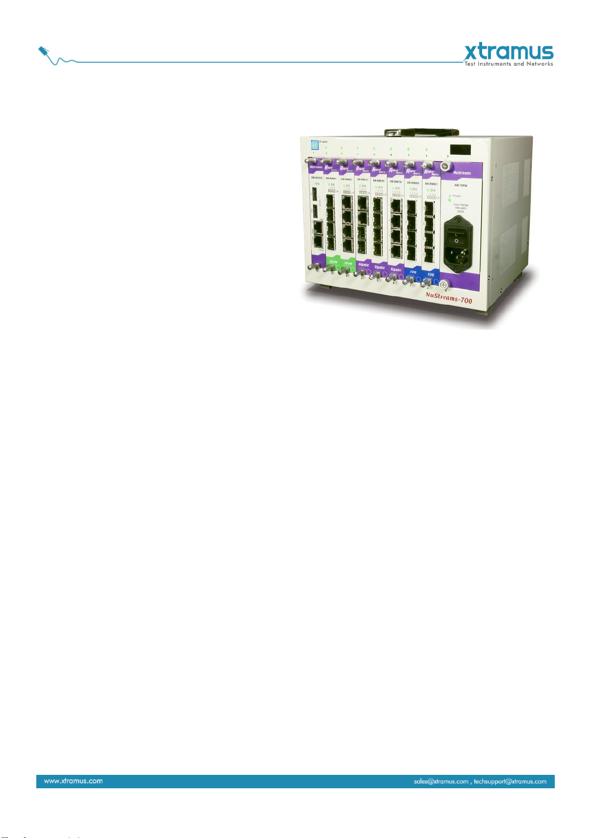
1.1. NuStreams-700 General Description...............................................................................4
1.2. Key Features of NuStreams-700......................................................................................5
1.3. Main Applications.............................................................................................................5
2. NuStreams-700 Functions and Structure Overview................................................................6
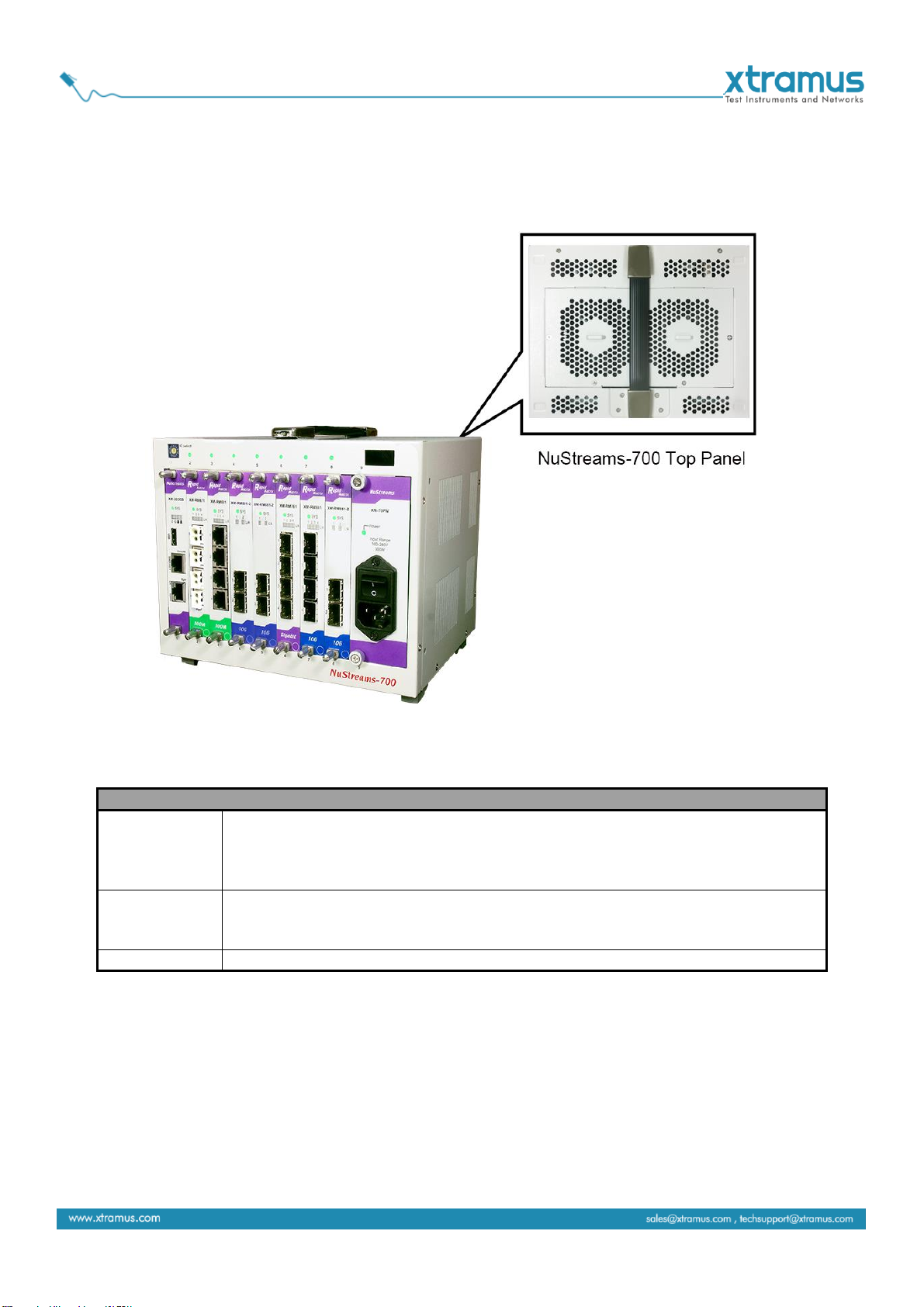
2.1. Structure Overview...........................................................................................................6
2.2. Replaceable Fans.............................................................................................................7
3. NuStreams-700 Installation.......................................................................................................8
3.1. Choices of UTP Cable and Optical fiber..........................................................................8
3.1.1. 10GBASE-T (Copper Wire)..........................................................................................8
3.1.2. 10GBASE-R (Optical Fiber).........................................................................................9
3.2. Hardware Installation......................................................................................................11
3.2.1. Bracket installation....................................................................................................11
3.2.2. Module Cards Installation .........................................................................................12
4. NuStreams-700’s Module Cards .............................................................................................13
4.1. System Module Cards ....................................................................................................14
A. XM-3S3GS........................................................................................................................14
B. XM-70PW .........................................................................................................................15
4.2. Measuring Module Cards...............................................................................................16
A. XM-RM661........................................................................................................................16
B. XM-RM671........................................................................................................................17
C. XM-RM681........................................................................................................................18
D. XM-RM731........................................................................................................................19
E. XM-RM751........................................................................................................................20
F. XM-RM761 ........................................................................................................................21
G. XM-RM781........................................................................................................................22
H. XM-RM881........................................................................................................................23
I. XM-RM882 .........................................................................................................................24
5. Example of suitable software for NuStreams-700.................................................................25
5.1. NuWIN-RM.......................................................................................................................25
5.2. NuApps-2544-RM............................................................................................................26
5.3. NuApps-MultiUnits-RM...................................................................................................28
6. Appendix –Other Utility Softwares for NuStreams-700........................................................29

4
1. NuStreams-700 Overview
1.1. NuStreams-700 General Description
Built on open software platform and a highly
scalable architecture, NuStreams-700 is highly
flexible and its functionality and applications can
be enhanced by applying software upgrade or
adopting new test modules.
NuWIN-RM, a powerful MS-Windows based
GUI, provides an easy way to configure and
control NuStreams-700 for different tests and to
monitor and gather test statistics. Users may
generate customized traffic patterns using
packet streams and easily configure packets
with incrementing, decrementing, or random
MAC addresses and through user-defined fields. Protocol editors are available for IP, UDP, IPX, TCP,
IGMP, MPLS, VLAN, and OSPF. Each port can generateARP requests and Ping requests and response
to such messages.
For switching device tests, users may use NuApps-2889-RM, an application software suite based on RFC
2889 and 2285, or NuApps-2544-RM, another suite based on RFC 1242 and 2544, to perform tests on
NuStreams-700.
In addition to the software suites provided by Xtramus, users may develop customized application
programs to take full advantage of NuStreams-700 by using the NuStreamsAPI. Customized mass
production test programs are also available to apply.
X-TAG, a feature for verifying the integrity of the embedded memory of a switch controller by checking an
unique tag attached to each packet sent from NuStreams-700 is supported by all test modules.
Intelligence chassis with enhanced fan development makes NuStreams-700 even more stable and
reliable. Chassis temperature and voltage are also measurable at all times.
NuStreams-700 is the most cost-effective, efficient and professional network performance testing and
analysis solution available on the market. The combination of high performance, multi-port traffic
generation and analysis functions, test modules, and reasonable pricing makes it the ideal solution for
R&D and Mass Production Test applications.

5
1.2. Key Features of NuStreams-700
Intuitive utility software for monitoring system temperature and the fan speed
All slots support hot-swapping
Performing synchronized tests between module cards
Multi-user function for module cards that can provide greater hardware-efficiency
Utility software provided by Xtramus Technologies which can analyze the test results and DUT
performance with intuitive GUI interface.
Module cards that work as management interfaces of NuStreams-700 are available and support
different Ethernet transferring rate.
Simple and easy-to-understand system status LEDs
Replaceable fan tray
Utility software that complied with RFC-2544 and RFC-2889
1.3. Main Applications
Performance validation and analysis of DUT in mass production line
Troubleshooting of DUT in the lab
Production testing and quality assurance during manufacturing process of network products

6
2. NuStreams-700 Functions and Structure Overview
2.1. Structure Overview
NuStreams-700’s outer case is dedicatedly designed in its Front Panel, Top Panel and Bottom Panel.
The figure above shows the outer case of NuStreams-700.
NuStreams-700 Outer Case Overview
Front Part
NuStreams-700 has 7 slots for installation of module cards, where each module
card provides streams generating platforms for different types of media.
Besides, the Front Part includes 2 slots with System and Power module card
installed, which should not be withdrawn.
Top Panel
On the top cover of the chassis, a plastic handle is set up for the convenience of
carrying it around. And replaceable fans are attached on the downside of the
cover.
Bottom Panel
Replaceable fans are attached on the upside of the cover.

7
2.2. Replaceable Fans
The fans for cooling the chassis attached to the Top & Bottom Panel are easily to replace. The steps to
replace the fans are:
1. Unscrew the screws on the Top/Bottom Panel
2. Open the Top/Bottom Panel
3. Disassemble the old fans and replace them with the new fans

8
3. NuStreams-700 Installation
As cited above, NuStreams-700 is a chassis with 7 slots for installation of module cards. Installing
NuStreams-700 is very easy and simple: all you have to do is to plug the proper fiber/UTP cables into
NuStreams-700 ports. Selecting the proper physical media and applications in your network environment is
crucial when installing NuStreams-700. Besides, using the proper method for installing module cards into
NuStreams-700’slots is also crucial for the proper functionality of NuStreams-700. Please see the sections
down below for detailed information regarding to physical media types and the proper method for installing
a module card.
3.1. Choices of UTP Cable and Optical fiber
3.1.1. 10GBASE-T (Copper Wire)
10GBASE-T, or IEEE 802.3an-2006, is a standard released in 2006 to provide 10 gigabit/second
connections over unshielded or shielded twisted pair cables and over distances up to 100 meters (330 ft).
10GBASE-T cable infrastructure can also be used for 1000BASE-T, allowing a gradual upgrade from
1000BASE-T, and auto-negotiation to select which speed to use.
10GBASE-T Connectors
10GBASE-T uses 650 MHz versions of the venerable IEC 60603-7 8P8C (RJ-45) connectors, which is
already widely used in Ethernet.
10GBASE-T Cables
10GBASE-T works up to 55 m (180 ft) with existing Category 6 cabling. In order to allow deployment at
the usual 100 m (330 ft), the standard uses a new partitioned Category 6a cable specification, designed
to reduce crosstalk between UTP cables.
The table down below is a reference regarding to UTP cable categories.
UTP Cable Categories References
Cat 5
Provides performance of up to 100 MHz, and was frequently used on 100 Mbps Ethernet
networks. Cat 5 may not be suitable for 1000BASE-T gigabit Ethernet.
Cat 5e
Provides performance of up to 100 MHz, and is frequently used for both 100 Mbps and
Gigabit Ethernet networks.
Cat 6
Provides performance of up to 250 MHz, more than double of category 5 and 5e. It works up
to 55 m (180 ft) for 10Gbps Ethernet.
Cat 6a
Provides performance of up to 500 MHz. It is suitable for
10GBASE-T and works up to 100 m (330 ft) for 10Gbps
Ethernet. All the cables mentioned above do not have
individually- shielded pairs as the picture here, including
Cat 6a.
Cat 7
This standard specifies four individually-shielded pairs (STP) inside an overall shield.
Designed for transmission at frequencies up to 600 MHz. It has better performance than Cat
6a.

9
3.1.2. 10GBASE-R (Optical Fiber)
10GBASE-R is 10Gbps Ethernet connection that based on IEEE802.3ae. It uses fiber as transmission
media with different specification of fiber, connector and transceiver. MCS-2160 uses two standards,
10GBASE-LR and 10GBASE-SR.
10GBASE-SR
10GBASE-SR ("Short Range") uses 64B/66B encoding and 850 nm wavelength lasers. It is designed to
support short distances over deployed multi-mode fiber cabling, it has a range of between 26 meters (85
ft) and 82 meters (270 ft) depending on cable type. It also supports 300 meters (980 ft) operation over
new, 50 μm 2000 MHzkm OM3 multi-mode fiber (MMF).
The transmitter can be implemented with a VCSEL (Vertical Cavity Surface Emitting Laser) which is low
cost and low power. MMF has the advantage of having lower cost connectors than SMF (single-mode
fiber) due to its wider core.
10GBASE-SR delivers the lowest cost, lowest power and smallest form factor optical modules.
10GBASE-LR
10GBASE-LR ("Long Range") is a Long Range Optical technology delivering serialized 10 gigabit
Ethernet over a laser with 1310 nm wavelength connection on single-mode fiber via IEEE 802.3 Clause
49 64B-66B Physical Coding Sub layer (PCS) using a line rate of 10.3125.
Single-mode optical cabling is used to interconnect transceivers at a distance spaced at 10 kilometers
(6.2 mi), but it can often reach distances of up to 25 kilometers (16 mi) with no data loss.
Fabry–Pérot lasers are commonly used in 10GBASE-LR optical modules. Fabry–Pérot lasers are more
expensive than VCSELs (mentioned above) but their high power and focused beam allow efficient
coupling into the small core of single mode fiber.
Fiber Specification
Fibers which support many propagation paths or transverse modes are called multi-mode fibers (MMF).
Fibers which can only support a single mode are called single-mode fibers (SMF). Multi-mode fibers
generally have a larger core diameter, and are used for short-distance communication links and for
applications where high power must be transmitted. Single-mode fibers are used for most
communication links longer than 200 meters.
Fiber Buffer/Jacket Color
Meaning
Yellow
Single-mode optical fiber, long distance connection
Orange
Multi-mode optical fiber, short distance connection

10
Optical Fiber
As mentioned above, there are Single-mode and Multi-mode optical fiber. Both of them can be used for
NuStreams module’s fiber port.
Fiber Connector
Optical fiber connector contains two ends of fibers and can attach
to SFP+ transceivers. There are two ports for one SFP+
transceiver: one fiber is for receiving and one fiber is for
transmitting. The picture here is called LC connector that can
attach to SFP+ transceiver.
Transceiver (Connector)
SFP+/XFP Transceivers can be plugged into NuStreams module’s SFP+/XFP
Ports. SFP+/XFP Transceivers are active components that consume power
from NuStreams module and are capable of converting signals between optical
data flow and electronic data flow.
For different transmission purpose, the component inside SFP+ form factor can
be 10BASE-LR or 10BAST-SR mode.

11
3.2. Hardware Installation
Please follow the steps shown below for a better understanding on how to install hardware in
NuStreams-700.
3.2.1. Bracket installation
Steps for installing a Bracket in NuStreams-700
First of all, you must have an Empty
Slot for the Installation of a Bracket.
Attach the Bracket’s screw end on the
internal Chassis’screw holes, and lock
the screw on the screw hole.
Note: we advise to use brackets to
close the unused slots of the
NuStreams-700 for internal protection.

12
3.2.2. Module Cards Installation
Steps for installing a XM-RM Module Card in NuStreams-700
Aim the border side of a XM-RM Module
Card with the NuStreams-700 internal
slide road, and push this Module Card
into the NuStreams-700.
Please, make sure if the XM-RM
Module Card is well fixed into
NuStreams-700 by pushing the bracket
of the XM-RM Module Card into
NuStreams-700.

13
4. NuStreams-700’s Module Cards
NuStreams-700’s module cards can be divided into two categories: System Module Cards and
Measuring Module Cards.
Module Card Type
Module Card
Description
System Module Cards
XM-3S3GS
XM-70PW
XM-3S3GS is the system management module of
NuStreams-700 and XM-70PW is the power
module of NuStreams-700.
Note: System Module Cards do not support
hot-swap, and must be installed to their
designated slots on NuStreams-700 chassis.
Measuring Module
Cards
XM-RM661
XM-RM671
XM-RM681
XM-RM731
XM-RM751
XM-RM761
XM-RM781
XM-RM881
XM-RM882
Measuring Module cards for Packets
sending/receiving. These Measuring Module
cards can be installed in NuStreams-700 support
hot-swap.
Please see the sections down below for more detail information regarding to NuStreams-700 Module
Cards.

14
4.1. System Module Cards
A. XM-3S3GS
The XM-3S3GS comes with your NuStreams-700 chassis, and shall be installed on the slot located on
the far left side of NuStreams-700 chassis. This module card allows you to connect your NuStreams-700
to your PC.
Interface Ports
Mgm Port
Connect to PC.
Console Port
RJ45 console port of 38400 baud rate for debugging.
USB Port
Reserved
LED
Sys
Yellow ON
XM-3S3GS is booting and preparing for test
Green ON
XM-3S3GS is booting properly and is ready for test
Green OFF
XM-3S3GS is power off
The USB port is being connected when Green ON.
The web management page of NuStreams-700 is being visited by
some user when Green ON.
The system is in single-user mode when Green ON.
The system is in multi-user mode when Green ON.
*Note: Please do not draw the XM-3S3GS module card from NuStreams-700 chassis when the system is power
on.

15
B. XM-70PW
The XM-70PW comes with your NuStreams-700 chassis, and shall be installed on the slot located on the
far right side of NuStreams-700 chassis.
LED
Power
Green ON
XM-70PW is power on
Green OFF
XM-70PW is power off
Fault
Yellow ON
XM-70PW is booting and preparing for test, or is power on but not
operating properly
Yellow OFF
XM-70PW is OFF or is operating
*Note: Please do not draw the XM-70PW module card from NuStreams-700 chassis when the system is power on.

16
4.2. Measuring Module Cards
A. XM-RM661
XM-RM661 Front Panel Specification
Interface
Port 1
SFP
Port 2
SFP
Port 3
SFP
Port 4
SFP
Data Transfer Rate
100 Mbps
LED Status
SYS
Green ON
The module card is operating
Yellow ON
(Blinking)
The module card is updating the Firmware
Yellow/Green
ON (Blinking)
The module card is booting and preparing for
test
L/A
Green ON
The port is currently linked
Green OFF
The port is currently link down
Green Blinking
The port is transmitting/receiving data.

17
B. XM-RM671
XM-RM671 Front Panel Specification
Interface
Port 1
POF
Port 2
POF
Port 3
POF
Port 4
POF
Data Transfer Rate
100 Mbps
LED Status
SYS
Green ON
The module card is operating
Yellow ON
(Blinking)
The module card is updating the Firmware
Yellow/Green
ON (Blinking)
The module card is booting and preparing for
test
L/A
Green ON
The port is currently linked
Green OFF
The port is currently link down
Green Blinking
The port is transmitting/receiving data.

18
C. XM-RM681
XM-RM681 Front Panel Specification
Interface
Port 1
RJ45
Port 2
RJ45
Port 3
RJ45
Port 4
RJ45
Data Transfer Rate
100 Mbps
LED Status
SYS
Green ON
The module card is operating
Yellow ON
(Blinking)
The module card is updating the Firmware
Yellow/Green
ON (Blinking)
The module card is booting and preparing for
test
L/A
Green ON
The port is currently linked
Green OFF
The port is currently link down
Green Blinking
The port is transmitting/receiving data.

19
D. XM-RM731
XM-RM731 Front Panel Specification
Interface
Port 1
RJ45 + SFP
Port 2
RJ45 + SFP
Data Transfer Rate
1000 Mbps
LED Status
SYS
Green ON
The module card is operating
Yellow ON
(Blinking)
The module card is updating the Firmware
Yellow/Green
ON (Blinking)
The module card is booting and preparing for
test
L/A
Green ON
The port is currently linked
Green OFF
The port is currently link down
Green Blinking
The port is transmitting/receiving data.
CAP
Green ON
The port is capturing data.
Table of contents
Other Xtramus Test Equipment manuals
Popular Test Equipment manuals by other brands

Intoximeters
Intoximeters Alco-Sensor FST Operator's manual

Horotec
Horotec Magtest MSA19.907 Description, Operating and Instructions for Use

Bante Instruments
Bante Instruments WXG-4 user manual

BIOS
BIOS Defender 530 Series user manual

Harris
Harris TS350 user guide

Brüel & Kjær
Brüel & Kjær 1019 instruction & application