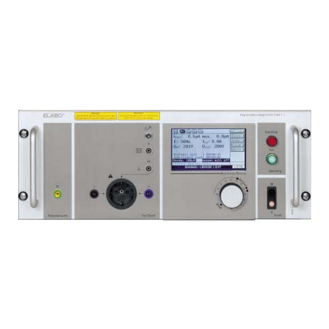
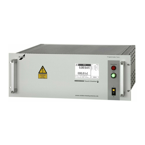
ELABO F1-1 Series User manual

Operating
instructions
Full-electronic
High Voltage-Tester
F1-1x
TestSystems
Service
Calibration at ELABO
Calibration at customer premises
Test units on loan
ELABO GmbH, Hotline ++49 7951/307-202
www.elabo-testsysteme.com

2
Full-electronic HV-Tester F1-1x
Contents
Contents
Content
1 INTRODUCTION ....................................................................... 9
1.1 General information ................................................................... 9
1.2 Abbreviations and symbols...................................................... 10
1.3 Short description of the testers ................................................ 10
1.4 Standards supported ............................................................... 12
1.5 Name plate .............................................................................. 12
2 SAFETY INSTRUCTIONS....................................................... 13
2.1 Markings for safety instructions and warnings......................... 13
2.2 Warranty .................................................................................. 13
2.3 Useasperspecicationsandexclusionofliability.................. 14
2.4 General rules of conduct and safety instructions .................... 14
2.5 Protective facilities / Emergency Off ........................................ 15
2.6 Operatorqualications............................................................. 15
2.7 Working clothes (personal protection equipment) and protection
at work ..................................................................................... 15
2.8 Maintenance ............................................................................ 15
2.9 Moisture and humidity.............................................................. 16
2.10 Physical/design changes to the system/device ....................... 16
2.11 Other information ..................................................................... 16
2.12 Information on the high voltage ............................................... 16
2.13 Discharging test objects with internal capacitance .................. 17
2.14 Discharging via the device....................................................... 17
3 PUTTING INTO OPERATION ................................................. 18
3.1 Transport and installation ........................................................ 18
3.2 Ambient conditions .................................................................. 18
3.3 Installation in housing or rack .................................................. 18
3.4 Connectiontotheconnectionbox/connectionpanel/test
system ..................................................................................... 19
3.4.1 Requirements for connecting lines to the test object........... 20
3.4.2 Cable length ....................................................................... 20
3.5 Mains connection..................................................................... 21
3.6 Using and controlling .............................................................. 21
3.7 Connection to the computer..................................................... 21
3.7.1 Connect USB-devices ......................................................... 22
3.8 Operating touchscreen display ................................................ 23
3.8.1 Entering arbitrary numerical values..................................... 23
3.8.2 Enteringarbitrarytext .......................................................... 24
3.9 Password protection ............................................................... 25
3.9.1 Password level 1 ................................................................. 25

3
Full-electronic HV-Tester F1-1x
Contents
3.9.2 Password level 2 ................................................................. 25
3.9.3 Password level 3 ................................................................. 25
3.10 Switching on ............................................................................ 27
3.11 Changing language.................................................................. 28
3.12 State past switch on HV/IS ...................................................... 29
3.12.1 Switch on HV/IS................................................................... 30
3.12.2 States IS.............................................................................. 31
3.13 Contact monitoring................................................................... 32
3.14 Safety circuits SK1 and SK2.................................................... 33
3.14.1 Fault in the device‘s safety circuit........................................ 33
3.15 Software-Update Display ......................................................... 33
4 OPERATING MODES ............................................................. 34
4.1 Overview ................................................................................. 35
4.2 HV/IS-test ................................................................................ 36
4.3 Current tripping modes ............................................................ 40
5 ERROR MESSAGES .............................................................. 41
6 CONNECTIONS / INTERFACES ............................................ 42
6.1 Power connections .................................................................. 42
6.1.1 High Voltage ........................................................................ 42
6.1.2 X6 Warning lamp set 94-2C connection ............................. 43
6.2 Interfaces ................................................................................. 44
6.2.1 RS232/USB/Ethernet interface X9 ...................................... 44
6.2.2 USB-Interface X8/ Ethernet-Interface X9a ........................ 44
6.2.3 Digital interface X7 .............................................................. 45
6.2.3.1 Outputs................................................................................ 45
6.2.3.2 Inputs................................................................................... 47
6.2.3.3 Additional digital interface OPT1-6 (option)......................... 48
7 ACCESSORIES AND ATTACHMENTS ................................. 49
7.1 Test cabinet (option) ................................................................ 49
7.2 Warning lamp set 94-2C ......................................................... 50
7.3 Test probes 94-2A.................................................................... 50
8 MAINTENANCE AND CARE .................................................. 51
8.1 Fuse replacement .................................................................... 51
8.2 Caring for the housing ............................................................. 51
8.3 Caring for the touchscreen display .......................................... 51
9 TECHNICAL DATA ................................................................. 52
9.1 Device-specictechnicaldata ................................................. 52
9.2 CommontechnicaldataF7-1x................................................. 53
9.2.1 HV test ................................................................................ 53
9.2.2 Insulation resistance measurement with HV-DC ................. 54

4
Full-electronic HV-Tester F1-1x
Contents
9.3 Interfaces, miscellaneous ....................................................... 55
9.4 Tester with current limitation
( 3 mA AC/5 mA DC) ...................... 55
10 TOUCHSCREEN DISPLAY MENU SYSTEM ........................ 56
10.1 General .................................................................................... 56
10.1.1 Overview,HVtestexample ................................................. 57
10.2 Main start menu ....................................................................... 58
10.3 Manual test .............................................................................. 59
10.4 Testing with last parameter settings......................................... 62
10.5 Load parameter ...................................................................... 63
10.6 Test plan management and automatic testing ......................... 65
10.6.1 Buttons ................................................................................ 65
10.6.2 Import/exportoftestplans.................................................. 66
10.6.3 Test plan Version Major /Minor ........................................... 66
10.7 Editing/adding test plans.......................................................... 67
10.8 Automatic testing - selecting test plans .................................. 70
10.8.1 Serial no. automatic............................................................. 71
10.9 Settings (device parameters)................................................... 72
10.9.1 Common.............................................................................. 72
10.9.2 Communication ................................................................... 74
10.9.3 Device ................................................................................. 75
10.9.4 ELABO ................................................................................ 77
10.9.5 Passwords........................................................................... 78
10.9.6 Special ................................................................................ 79
10.9.7 Time/Date ........................................................................... 80
11 TEST PARAMETERS.............................................................. 81
11.1 Setting parameters high voltage test ...................................... 81
11.1.1 Test voltage ......................................................................... 81
11.1.2 Ramp function ..................................................................... 83
11.1.3 Test time .............................................................................. 84
11.1.4 Tripping current ................................................................... 85
11.2 Setting parameters insulation resistance test IS..................... 87
11.2.1 Test voltage ......................................................................... 87
11.2.2 Ramp function ..................................................................... 89
11.2.3 Test time .............................................................................. 90
11.2.4 Range.................................................................................. 91
11.3 Setting parameters Burn (Option)........................................... 93
11.3.1 Test voltage ......................................................................... 93
11.3.2 Ramp function ..................................................................... 94
11.3.3 Test time .............................................................................. 95
11.4 Setting parameters function test (FK)..................................... 96

5
Full-electronic HV-Tester F1-1x
Contents
11.4.1 Voltage................................................................................. 96
11.4.2 Ramp / time ......................................................................... 97
11.4.3 Tripping................................................................................ 98
12 UNIVERSAL TEST STEPS ..................................................... 99
12.1 Create universal test steps ..................................................... 99
12.2 Info step ................................................................................. 100
12.3 Question step......................................................................... 101
12.4 Pause step............................................................................. 101
12.5 Output step (Option) .............................................................. 102
13 RESULT BROWSER (OPTION)............................................ 103
13.1 Limitationofselection/lter ................................................. 103
13.2 Display list.............................................................................. 105
13.3 Showing/printing measurements ........................................... 106
14 OPTIONS AND ADD-ONS FOR THE DEVICES .................. 108
14.1
Safety current limitation Option E03 ...................................... 109
14.1.1 Load characteristic current-limited......................................110
14.2 Voltage Readback unit E04 ...................................................112

6
S3/H3 S2/H2
TouchDisplay H4
H3 S2/H2
S1/H1
S1/H1
X11 X12
Full-electronic HV-Tester F1-1x
1. INTRODUCTION
Info about device versions and options
The device can be delivered with some optional features, this options
are completes or enhances the performance range of the device. Some
optional features are only as single option possible. ELABO completes
the number of options constantly (as required). Optional features of the
device,aredescribedintheappendix13„options“
A OPERATING ELEMENTS

7
X9a X7 X6 X4 X2
F1/X1 X5 X3X9 X8
X2 X3
Full-electronic HV-Tester F1-1x
1. INTRODUCTION
Note HV-tester with oating output voltage:
Connect the " -/~ " pole of the test voltage (hot pole) to the housing (PE)
of the test object. This is necessary to get a high- possible measuring
accuracy.
High voltage tester F1-1D 12/16 KV

8
Full-electronic HV-Tester F1-1x
1. INTRODUCTION
No. Equipment Function
F1 Fuse drawer Adapter for mains fuse
S1/H1 Toggle switch/pilot lamp Mains switch with indicator lamp
S2/H2 Illuminated button Reset (red) Switching OFF test voltage / Reset
S3/H3 Illuminated button Set (green)
Read for testing
Starting test run (only at display devices)
H4 TouchDisplay Operating of the tester
X1
Cold appliance mounting jack with
fuse adapter 10 A
Maincableconnection/mainsfuse(newirefuse
T6.3A-5x20mm)
X2 HV-jack Connection high voltage + / ~ (high potential)
X3 HV-jack Connection high voltage - / ~ (low potential)
X4 HV-jack Feed back of high voltage ( + / ~) for X2 (Option)
X5 HV-jack Feed back of high voltage ( - / ~) for X3 (Option)
X6 Socket (Warning Lamps) Connection warning lamps
X7 Socket (D-SUB 25pole) female DA-interface - digital Inputs/Outputs, Safety circuit
X8 USB - socket
For USB devices (memory stick, etc) , software
update via USB-stick - only available at tester with
display.
X9 RJ45 - socket Ethernet bus interface
X9a RJ45 - socket (option)
Ethernetbusinterfaceforcommunicationtoexternal
devices (function units, switching units. ect.)
X11 HV-jack Connection high voltage - parallel to X2
X112 HV-jack Connection high voltage - parallel to X3

9
Full-electronic HV-Tester F1-1x
1. INTRODUCTION
1 INTRODUCTION
The safety of all personnel who come into contact with the tester essentially
depends on an adequate understanding of the device. For this reason:
Prior to the rst putting into operation read these operating in-
struction!
Note on operating instructions!!
These operating instructions apply to devices with and without the
touchscreen display. The menus shown can be useful for illustrating
the functions on devices without a display and therefore contribute
to an improved understanding of the device.
1.1 General information
These operating instructions will make it easier to become familiar with
tester and its possible uses prior to placing in operation, and to use it
correctly. They contain information that will ensure functionally correct,
cost-effective and safe operation and they must always be available in
the place where the device is used.
The operating instructions are not only an indispensable aid for new trainee
operators, they also contain useful tips, information and suggestions for
theexperiencedoperator.Theyareanecessaryreferenceworkforall
users. By reading the operating instructions
•Hazards will be avoided
•Operating sequences will be optimised and accelerated
•Repair costs and downtimes will be minimised
•Reliability and service life will be increased
The operating instructions should also be read carefully by the device
owners and managerial staff. In particular in relation to transport and in-
stallation, as well warranty aspects.
In chapter 2 important safety instructions and information about hazards
is given that will prepare you for hazardous situations that may occur.
Reading up during operation is unfortunately too late. Also note the fol-
lowing basic principle:
Cautious and careful working is the best protection from acci-
dents!
The quality of the tests performed using the device is crucially depend-
ent on maintenance and care. Regular maintenance work and care are
described in these operating instructions. If repairs are necessary, we will
be pleased to provide you with support and supply you with the necessary
original spare parts.
If you have questions after reading the operating instructions, the ELABO
hotline (telephone +49 7951/307-202) is available to provide information.

10
SO
•1
•
Full-electronic HV-Tester F1-1x
1. INTRODUCTION
1.2 Abbreviations and symbols
Special option that is not included as standard
List, here the recommended sequence of actions is to be followed
List
CAUTION ELECTRIC HIGH VOLTAGE - DANGER TO LIFE!
Hazardous point, risk of serious injury to the operator and other person-
nel! - chapter 2.1
Risk for the device! - chapter 2.1
Informationonefcientandcost-effectiveoperation-chapter2.1
1.3 Short description of the testers
The testers F1-1A, -1B, -1C, 1D are designed for operation by using the
integrated touchscreen display and also via the serial or USB interface.
As an alternative, the devices F1-1M, -1N, -1P, -1Q are intended to be
controlledusinganexternalPC/PLC.Forthisreasonthereisnodisplay.
The modular design of the tester permits optimal adaptation to the indi-
vidualneedsoftheuser.Expansionmodules,standardaccessoriesand
individual accessories offer the right solution for every application.
The basic devices available are automated devices (without display) for
useintestsystemsand„stand-alone“devices(withdisplay).
The uses for the device family range from an individual manually operated
test bench, through a PC-controlled test station (with control, evaluation,
statisticsandtestplanmanagementviaPCsoftware)toacomplexfully
automatic test station with conveyor belt, autom. contact, labeling etc..
ELABO offers a modern software package for controlling this device series
and the management of the data via a PC.
Devices with touchscreen display
The user can be operated entirely using the touchscreen panel. This
operation covers the control of the device during the test, the generation
and management of test steps and test plans.
The display informs the operator at all times about the parameters and
the status of the tests.
HV section:
The device is used to perform an insulation and dielectric strength test on
electrical devices, machinery, components and insulating materials that,
in accordance with the applicable safety regulations, must be tested using
a sinusoidal AC voltage or DC voltage.
The high voltage is primarily generated using an internal HV source with
a high clock frequency and is regulated fully electronically. As a result the
HV settles within less than 10 ms.

11
Full-electronic HV-Tester F1-1x
1. INTRODUCTION
The electronic voltage ramp up makes it possible to perform tests on
electronic devices that can only be tested non-destructively by slowly in-
creasing the test voltage or on test objects with high self-capacitance. Due
to the fully electronically regulated test voltage, the variable transformer
otherwise used is not necessary. The current and voltage measurements
are made on the high voltage side. An integrated residual voltage meas-
urement ensures safe discharge of test object capacitance.
Theinternalmodulescommunicateviaopticalbre,asaresultmutual
electricalinterferenceislargelyexcluded.
Complexcurrent,realcurrentorpeakvalueofthetestcurrentcanbe
selected as the tripping method. In addition, for each tripping method a
maximumpermissiblecurrentchange(delta-I)canbedened.Toensure
the contact to the test object is made correctly, a minimum test current
(Imin)canbedenedasaformofcontactmonitoring.
ISO section (option)
Insulation resistance measurement with voltages from 200 V to 6000 V
or 8000 V DC at full HV current.
Attention high voltage mortal danger! The resistance measurement is
not current-limited, it is performed with the full HV current (up to 100 mA).
PC software (option)
By controlling the tester via a PC/PLC all the advantages of modern soft-
warecanbeexploited.Graphic,colouruserpromptsenabletheoperator
to see the status of the tests at a glance. Test parameters can be saved
in test plans, access control using passwords is possible. The test data
can be evaluated using Accept/Fault statistics. Other advantages are
the acquisition of barcodes using scanners, data integration via in-house
networks, communication with conveyor belt controllers, etc..
Important note: To connect the test object to the device, a connection
boxoraconnectionpanelisrequired.Anotherpossibilityisinstallationin
a test system (rack) with suitable power supply and switch panel.

12
SN. 0000042483
ELABO GmbH
Rossfelder Str. 56
D-74564 Crailsheim
Telefon: +49 7951 307-0
Telefax:+497951307-65
Nennspg. V
~
Nennstrom A
Typ
Baujahr
230 V ; 49 - 61 Hz
6,3 A
F1-1A
2008
Full-electronic HV-Tester F1-1x
1. INTRODUCTION
1.4 Standards supported
The device supports tests, e.g., in accordance with:
• EN 60335-1 Household and similar electrical appliances. Safety
• EN 60598-1 Luminaires
• EN 60950 Information technology equipment. Safety
• EN 61010-1 Safety regulations for electric measurement, control
and laboratory equipment
• EN 60601 Medical electrical equipment
1.5 Name plate
ELABO tester
Thenameplate(example)isontherearofthedevice.

13
Full-electronic HV-Tester F1-1x Typs
2. SAFETY REGULATIONS
2 SAFETY INSTRUCTIONS
Before working with the tester the operating instructions and all enclosures
must have been attentively read and understood by all persons operating the
tester. The tester may be operated by trained and skilled staff only.
When the device is in operation, voltages of up to 5000 AC / 6000 DC Volt
canbeproduced.Ifthedeviceisttedwithoptions,signicantlyhigher
voltages can occur. There is mortal danger when working with high
voltage! ELABO has therefore equipped this device and all its components
with all the necessary safety features to protect the user against hazards
that may occur during correct use. Please note:
CAUTIOUS AND CAREFUL WORKING IS THE BEST PROTECTION
FROM ACCIDENTS !
2.1 Markings for safety instructions and warnings
Danger Zone
Electric High Voltage - danger to life !
IN DEALING WITH HIGH VOLTAGE THERE IS DANGER TO LIFE!
This marking warns of a point that is hazardous due to high electrical volt-
age. It is given beside all work steps during which there is risk of serious
injury for the operator or others. It is given beside working and operating
proceduresthataretobefollowedexactlytoensurepeopleorthetester
are not endangered by high electrical voltage.
PAY ATTENTION TO THE NOTES AND ACT VERY CAREFUL IN
THESE SITUATIONS. ALSO PASS ALL SAFETY REGULATIONS ON
TO OTHER OPERATORS.
Caution !
Thissignsigniesdanger for the tester in case of non-observance of
instruction.
Note!
Thissignsigniesthatamoreeffectiveandmoreeconomicuseofthe
tester is possible.
2.2 Warranty
Claims under the warranty can only be made if the warranty conditions
in the general terms and conditions are followed. The conditions in the
operating instructions are also to be observed.

14
Full-electronic HV-Tester F1-1x Typs
2. SAFETY REGULATIONS
2.3 Use as per specications and exclusion of liability
The tester is only allowed to be used for the intended tests. Any other usage
is considered incorrect. ELABO is not liable for any resulting damage, the
risk is borne solely by the user. Correct usage also includes compliance
with the information in these operating instructions.
The tester and its components have been developed and built for usage
in an industrial environment. In accordance with DIN EN 55022 ITE, this
system is a class A appliance. Neither the tester as a complete unit nor its
individual components are allowed to be used in a different environment.
If this information is not followed, ELABO accepts no liability whatsoever
for any interference produced and the resulting damage.
Prior to working with the tester, these operating instructions and all appen-
dices must be carefully read and understood by all personnel operating
the tester. The tester is only allowed to be operated by trained personnel.
Thesafetyfeaturesanddesignofthetesterarenotallowedtobemodied.
AnychangerequirestheexpressagreementofELABO.
Unauthorised changes to the tester, as well as the usage of spare parts,
accessories and additional equipment that has not been tested and ap-
proved by ELABO may degrade the function and properties of the tester.
ELABO is not liable for resulting damage.
ELABO does not accept any liability for damage resulting from the failure
to follow the operating instructions or due to failure to take due care dur-
ing transport, installation, handling, operation, care and maintenance or
repairofthedevice,evenifspecicmentionofthisdutytotakecareis
notspecicallyhighlightedintheseoperatinginstructions.
2.4 General rules of conduct and safety instructions
The tester is built to the state-of-the-art and recognised safety rules. Never-
theless, during operation there may be a risk of serious injury to the user
or other personnel, or damage to the device or other property.
The tester is only allowed to be used in correct working order and correct-
ly taking into account the operating instructions. Malfunctions that may
degradesafetyaretoberectiedwithoutdelay.
Managerial staff must ensure personnel tasked with working on the tester
have read and understood the operating instructions prior to starting work.
The managerial staff have the obligation to only ever operate the device in
correct working order and to ensure the operators use the tester correctly.

15
Full-electronic HV-Tester F1-1x Typs
2. SAFETY REGULATIONS
These operating instructions must always be available in the place the
device is installed. Incomplete or illegible operating instructions are to be
replaced without delay. In this situation we would of course be pleased to
be of assistance.
In addition to the operating instructions, statutory, generally applicable
and other binding regulations for the prevention of accidents and for the
protection of the environment are to be followed.
Note:
DIN EN 50191 (VDE 0104) regulates the operation of test systems.
Follow the stipulations in the DIN standard.
2.5 Protective facilities / Emergency Off
- All the system‘s safety features are to be checked for correct function prior to putting
into operation each day.
- Prior to placing the system in operation, all safety features must be cor-
rectlyttedandfunctional.
- Safety features are only ever allowed to be removed for repair.
- Safety limit switches are not allowed to be bypassed.
2.6 Operator qualications
-Theoperatorsmustholdanappropriatequalicationtooperatethesys-
tem. The operators must be informed and instructed about the function
and especially the risks and hazards related to the system.
- Anybody who works on the system must have read the operating instruc-
tions, be familiar with the content and follow it.
- The responsible superior has the obligation to instruct the personnel
based on the operating instructions.
- Temporary employees and trainees are only allowed to work on the sys-
temunderthesupervisionofappropriatelyqualiedpersonnel.
-Theresponsibilitiesofthepersonnelaretobeclearlydened.
2.7 Working clothes (personal protection equipment) and
protection at work
- Wear the necessary working clothing for your activity, e.g. ESD footwear,
safetyshoes,ame-retardantclothing,etc.Obtaininformationonthis
issuefromyoursupervisororthesafetyofcer.
- If necessary, wear hearing protection.
2.8 Maintenance
- The stipulated maintenance and inspection work is to be performed at
theintervalsdened.
DIN EN 50191

16
Full-electronic HV-Tester F1-1x Typs
2. SAFETY REGULATIONS
- Inform operators prior to starting maintenance and service work.
- During all maintenance and inspection work, electrically isolate the device
/systemandsecureagainstunexpectedswitchon.
- The work is only allowed to be undertaken by appropriately trained per-
sonnel, all safety precautions are to be taken.
- To perform maintenance and servicing work, workshop equipment ap-
propriate for the work to be performed is imperative!
2.9 Moisture and humidity
- The parts of the system are not allowed to be subject to moisture, hu-
midity and/or dust.
- Particularly the electrical parts and the test mechanism and test sensors
for the system must be protected against moisture, humidity and dust.
Compliance with the technical data
-Thetechnicalperformancedataasperthenameplatemustnotbeex-
ceeded.
- The fuse protection for the supply cables must not be higher than the
max.valuedenedbyELABO.
2.10 Physical/design changes to the system/device
Without the prior written approval of ELABO, it is not allowed to make
changes,additionsormodicationstothesystem.Ifthisinstructionisnot
followed, the device/machine/system will lose its EC conformity.
- Immediately replace parts that are not in correct working condition.
- Only use genuine spare parts. Only these comply with the technically
denedrequirements.
2.11 Other information
Escape routes: The escape routes are to be kept clear.
In accordance with UVV „Elektrische Anlagen und Betriebsmittel“
(Electrical systems and equipment) (BGV A2) §2, paragraph 3 the
term Elektrofachkraft (electrician)isdenedasfollowed(translationof
theoriginalGermantext):
Anelectricianinthecontextofthepreventionofaccidentsisaperson
who,duetohis/herspecialisttraining,knowledgeandexperience,aswell
as knowledge of the application regulations is able to assess the work
allocated and recognise possible hazards.
2.12 Information on the high voltage
Attention high electrical voltage - mortal danger!
IN DEALING WITH HIGH VOLTAGE THERE IS DANGER TO LIFE!
When performing tests using the device you will be working with a high
voltage up to 6000 Volt AC or 8000 Volt DC.Ifthedeviceisttedwith
options,signicantlyhighervoltagescanoccur.There is mortal danger

17
Full-electronic HV-Tester F1-1x Typs
2. SAFETY REGULATIONS
when working with high voltage!
Follow DIN EN 50191 (DIN VDE 0104). The EN standard regulates the
operation of test systems and test benches.
Attention high voltage: The contact elements used for the HV and IS
test(testprobesetc.)mustbedesignedforthemaximumvoltagesupplied
by the device.
2.13 Discharging test objects with internal capacitance
Attention discharge currents - mortal danger!! particularly in
the case of test objects with internal capacitance (capacitors).
Particularly during tests with DC, test objects with internal capacitance
can store large amounts of charge. After disconnecting, this charge
may be dissipated via the operator‘s body (if the test object is touched in
the appropriate place).
If the test object is left connected to the tester after switching off the high
voltage, it will discharge automatically via the tester. If this discharging
is prevented (disconnection), potentially fatal discharge currents may be
produced.
Note Mains Switch: Do not switch-off the Tester on running HV-/IS-test.
In this case, a correct discharge of the test object not ensure.
2.14 Discharging via the device
After the end of the test (end of test time), the test object connected is au-
tomatically discharged. For this purpose a discharge resistor is connected
internally and the voltage across the resistor read (residual voltage meas-
urement) The discharging is undertaken using an internal 5 MOhm resistor
until a voltage of 3000 V is reached, the device then connects a 2 MOhm
resistor in parallel. If the voltage doesn‘t underrun a residual voltage of 60 V
within - 10 s at DC / 500 ms at AC - the device indicates the fault message
„Attentionresidualvoltage“.
Note: Theresidualvoltagemeasurementcanbeswitchedoffonthe„Setup“
menu or using an interface command (see the remote control manual).
Automatic discharging is performed only at DC test voltages. At AC, the
discharging of the test object is running via high-voltage transformer.
Attention: Leave the test object connected until it is discharged. The
device indicates this state with the illumination of the green RUN button.
Additional discharging via an external resistor
The devicehasanoutputfortheconnectionofanexternaldischargere-
sistor. At the end of the HV/ IS test this output is connected by the device.
Onthistopicseechapter6.2.4.1„Outputs/externaldischargerelay“.

18
Full-electronic HV-Tester F1-1x Typs
3. MAKEREADY
3 PUTTING INTO OPERATION
3.1 Transport and installation
The tester is supplied fully packed and is only allowed to be removed from
the packaging in the immediate vicinity of the installation location.
Thedevicecanbeinstalledinasuitableindustrialrackorhousingfor19“
plug-ins. The device must be secured against unintentional movement.
The surface on which the device is installed must be appropriate for the
weightofthetester(approx.50kg!)andalwaysprovideasecuremount-
ing for the device.
During installation it is to be ensured the labels with information and safety
labels on the device are not covered.
3.2 Ambient conditions
Thetesterisnotallowedtobeoperatedinadusty,inammable,aggres-
sive or humid environment. The values permitted for temperature and
atmospherichumidityaregiveninchapter1.4„Maintechnicaldata“.
3.3 Installation in housing or rack
Note: Slide the device carefully to the rear to the stop. Do not jam the
device on insertion.
After the inserting the device in a housing, it must be secured at the front
using 4 screws.
Operation with a loosely inserted tester is not allowed!
Installation without a modular system or housing is not allowed.
Fig.3.1:Testerwithoutdisplayinstalledin19“/6HUhousing

19
Full-electronic HV-Tester F1-1x Typs
3. MAKEREADY
F1-1x
X3/X12
X2/X11
IS
F1-1x
X3/X12
X2/X11
HV
3.4 Connection to the connection box / connection panel /
test system
Fig. 3.2: Principle of connection HV
Connectionbox
Test object
Fig. 3.3: Principle of connection IS (same as HV)
Connectionbox
Test object
Mains plug X1
Mains plug X1

20
Full-electronic HV-Tester F1-1x Typs
3. MAKEREADY
3.4.1 Requirements for connecting lines to the test object
Under the requirements (current, voltage, mechanical stress, handling, et
cetera),mustbeusedappropriateandcerticatedconnectingcablesand
contacting devices.
Use high quality cables: Insulation material with: - a low dielectric con-
stant; -low dielectric loss factor; - a high insulation resistance. In addition,
an effectual voltage strength, is necessary.
Voltage strength:Theconnectinglinesmustbecerticatedandtested,
forthemaximumvoltageofthetestdevice.
Current: The connecting lines must be certicated and tested, for the
maximumcurrentofthetestdevice.Haveattentionforcontinoustest.
Mechanical stress: The connecting lines must be constructed for the
mechanical stress, at the test place. If necessary, - place the cables in
safety positions; - use a cable protective tube; - or use other approbate
precautions .
Handling: The connecting lines must be well to handling. Use elastic,
ne-wirecables,withsufcientlengths.Haveattentionfortheweightof
the cables.
Have attention for other risks on the test place eg. humidity, hotness,
chemical hazard ... .
3.4.2 Cable length
The length of the measurement lines must be constructed, as long as
necessary,howeverasshortaspossible.Longconnectinglinesexhibit
possiblyarelativelyhighreactivepart.Ithasasubstantialinuenceonthe
high voltage measurement, in the small measuring range (special with 3
mA devices). A similar case is valid for the insulation resistance measure-
ment, in the 100 MOhm range.
This manual suits for next models
10
Table of contents
Other ELABO Test Equipment manuals
Popular Test Equipment manuals by other brands

PUTCO
PUTCO HORNET 2019+ DODGE RAM 1500 Instruction guide
IKONIX
IKONIX Associated Research HYAMP III Operation and service manual
Fluke
Fluke 635 QuickBERT-T1 Manual supplement

Fieldpiece
Fieldpiece MR45UK 110VAC Operator's manual

XTBA
XTBA DALI Watch manual
Ashcroft
Ashcroft 1327D Installation and maintenance manual


