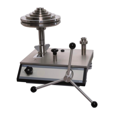
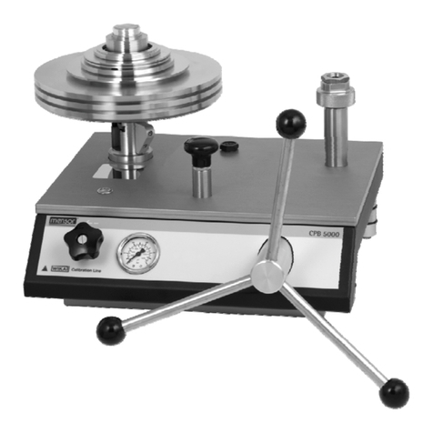
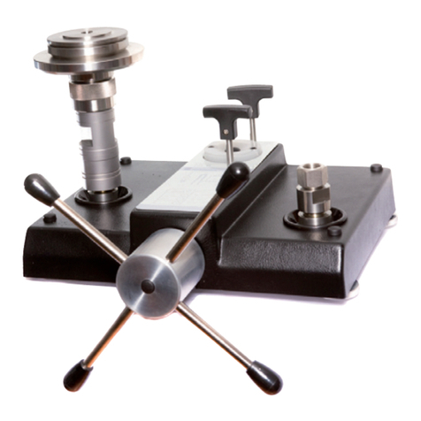
WIKA CPB3500 User manual

Operating instructions
Betriebsanleitung
EN
DE
Pneumatic dead-weight tester, model CPB3500
Pneumatische Druckwaage, Typ CPB3500
Pneumatic dead-weight tester, model CPB3500

2WIKA operating instructions, model CPB3500
14147066.01 06/2023 EN/DE
EN
DE
© 06/2023 WIKA Alexander Wiegand SE & Co. KG
All rights reserved. / Alle Rechte vorbehalten.
WIKA®is a registered trademark in various countries.
WIKA®ist eine geschützte Marke in verschiedenen Ländern.
Prior to starting any work, read the operating instructions!
Keep for later use!
Vor Beginn aller Arbeiten Betriebsanleitung lesen!
Zum späteren Gebrauch aufbewahren!
Operating instructions model CPB3500 Page 3 - 42
Betriebsanleitung Typ CPB3500 Seite 43 - 82
Further languages can be found at www.wika.com.

3WIKA operating instructions, model CPB3500
14147066.01 06/2023 EN/DE
EN
Contents
1. General information 5
1.1 Abbreviations, definitions. . . . . . . . . . . . . . . . . . . . . . . . . . 5
1.2 Explanation of symbols . . . . . . . . . . . . . . . . . . . . . . . . . . 6
2. Short overview 6
2.1 Overview . . . . . . . . . . . . . . . . . . . . . . . . . . . . . . . 6
2.2 Description . . . . . . . . . . . . . . . . . . . . . . . . . . . . . . 7
2.3 Scope of delivery . . . . . . . . . . . . . . . . . . . . . . . . . . . . 7
3. Safety 8
3.1 Intended use . . . . . . . . . . . . . . . . . . . . . . . . . . . . . . 8
3.2 Improper use . . . . . . . . . . . . . . . . . . . . . . . . . . . . . . 8
3.3 Personnel qualification . . . . . . . . . . . . . . . . . . . . . . . . . . 9
3.4 Personal protective equipment . . . . . . . . . . . . . . . . . . . . . . . . 9
4. Transport, packaging and storage 10
4.1 Transport . . . . . . . . . . . . . . . . . . . . . . . . . . . . . . . 10
4.2 Packaging and storage . . . . . . . . . . . . . . . . . . . . . . . . . . 10
5. Design and function 11
5.1 Description . . . . . . . . . . . . . . . . . . . . . . . . . . . . . . 11
5.2 Base . . . . . . . . . . . . . . . . . . . . . . . . . . . . . . . . 11
5.3 The piston-cylinder system model CPS3500 . . . . . . . . . . . . . . . . . . . 12
5.4 Piston range . . . . . . . . . . . . . . . . . . . . . . . . . . . . . . 13
5.4.1 Range 0.015 ... 1 bar (pure gas) . . . . . . . . . . . . . . . . . . . . . . . . . . . . . . . . . 13
5.4.2 Range 0.1 ... 7 bar (pure gas) . . . . . . . . . . . . . . . . . . . . . . . . . . . . . . . . . . . 13
5.4.3 Range 0.2 ... 25 bar (pure gas) . . . . . . . . . . . . . . . . . . . . . . . . . . . . . . . . . . 14
5.4.4 Range 1 ... 70 and 1 ... 120 bar (oil-lubricated, gas-operated) . . . . . . . . . . . . . . . . . 14
5.5 Function . . . . . . . . . . . . . . . . . . . . . . . . . . . . . . . 14
6. Commissioning, operation 15
6.1 Unpacking the dead-weight tester. . . . . . . . . . . . . . . . . . . . . . . 15
6.2 Ambient conditions. . . . . . . . . . . . . . . . . . . . . . . . . . . . 15
6.3 Installing the base . . . . . . . . . . . . . . . . . . . . . . . . . . . . 16
6.4 Assembly of the dead-weight tester . . . . . . . . . . . . . . . . . . . . . . 16
6.5 Connecting the pneumatic pressure supply . . . . . . . . . . . . . . . . . . . 16
6.6 Connection of the test item . . . . . . . . . . . . . . . . . . . . . . . . . 17
6.7 Post-assembly test . . . . . . . . . . . . . . . . . . . . . . . . . . . . 18
6.8 Pressure calibration . . . . . . . . . . . . . . . . . . . . . . . . . . . 18
6.8.1 Procedure all positive pressure units . . . . . . . . . . . . . . . . . . . . . . . . . . . . . . . 18
6.8.2 Procedure vacuum calibration -1 ... -0.015 bar . . . . . . . . . . . . . . . . . . . . . . . . . 18
6.8.3 Inlet and vent valves . . . . . . . . . . . . . . . . . . . . . . . . . . . . . . . . . . . . . . . . 19
6.8.4 During calibration . . . . . . . . . . . . . . . . . . . . . . . . . . . . . . . . . . . . . . . . . 19
6.8.5 Pressure range 1 ... 70 bar and 1 ... 120 bar only! . . . . . . . . . . . . . . . . . . . . . . . . 20
6.9 Completion . . . . . . . . . . . . . . . . . . . . . . . . . . . . . . 20
6.10 Temperature measurement of piston . . . . . . . . . . . . . . . . . . . . . . 20
6.11 Cleaning the measuring instruments . . . . . . . . . . . . . . . . . . . . . . 21
Contents
4WIKA operating instructions, model CPB3500
14147066.01 06/2023 EN/DE
EN
Contents
7. Faults 22
8. Maintenance, corrective maintenance, cleaning and calibration 23
8.1 Periodic maintenance . . . . . . . . . . . . . . . . . . . . . . . . . . . 23
8.2 Corrective maintenance . . . . . . . . . . . . . . . . . . . . . . . . . . 24
8.2.1 Removing the cover . . . . . . . . . . . . . . . . . . . . . . . . . . . . . . . . . . . . . . . . 24
8.2.2 Replacing seals on inlet valve and vent valve . . . . . . . . . . . . . . . . . . . . . . . . . . 25
8.2.3 Inlet valve and vent valve testing procedure . . . . . . . . . . . . . . . . . . . . . . . . . . . 25
8.2.4 Volume adjuster . . . . . . . . . . . . . . . . . . . . . . . . . . . . . . . . . . . . . . . . . . 25
8.2.5 Replacing the seal of pressure measuring instrument . . . . . . . . . . . . . . . . . . . . . 26
8.2.6 Piston-cylinder system. . . . . . . . . . . . . . . . . . . . . . . . . . . . . . . . . . . . . . . 26
8.2.7 Spare seal . . . . . . . . . . . . . . . . . . . . . . . . . . . . . . . . . . . . . . . . . . . . . 27
8.3 Cleaning . . . . . . . . . . . . . . . . . . . . . . . . . . . . . . . 28
8.3.1 Cleaning the unit and checking the liquid levels . . . . . . . . . . . . . . . . . . . . . . . . . 29
8.3.2 Cleaning of the piston-cylinder system. . . . . . . . . . . . . . . . . . . . . . . . . . . . . . 29
8.4 Calibration. . . . . . . . . . . . . . . . . . . . . . . . . . . . . . . 30
8.4.1 Overhaul and calibration of dead-weight testers, maintenance of accuracy . . . . . . . . . 30
8.4.2 Need for overhaul and calibration. . . . . . . . . . . . . . . . . . . . . . . . . . . . . . . . . 30
8.4.3 Identification of masses . . . . . . . . . . . . . . . . . . . . . . . . . . . . . . . . . . . . . . 30
8.4.4 Overhaul and calibration. . . . . . . . . . . . . . . . . . . . . . . . . . . . . . . . . . . . . .30
9. Return and disposal 32
9.1 Return . . . . . . . . . . . . . . . . . . . . . . . . . . . . . . . . 32
9.2 Disposal . . . . . . . . . . . . . . . . . . . . . . . . . . . . . . . 32
10. Specifications 33
10.1 Piston-cylinder system . . . . . . . . . . . . . . . . . . . . . . . . . . 33
10.2 Base . . . . . . . . . . . . . . . . . . . . . . . . . . . . . . . . 34
10.3 Certificates . . . . . . . . . . . . . . . . . . . . . . . . . . . . . . 34
10.4 Tables of masses . . . . . . . . . . . . . . . . . . . . . . . . . . . . 35
10.5 Transport dimensions for complete instrument . . . . . . . . . . . . . . . . . . 37
10.6 Dimensions in mm [in]. . . . . . . . . . . . . . . . . . . . . . . . . . . 38
10.6.1 Base. . . . . . . . . . . . . . . . . . . . . . . . . . . . . . . . . . . . . . . . . . . . . . . . . 38
10.6.2 Test connection . . . . . . . . . . . . . . . . . . . . . . . . . . . . . . . . . . . . . . . . . . 40
10.6.3 Standard connection piston-cylinder system . . . . . . . . . . . . . . . . . . . . . . . . . . 40
11. Accessories 41

5WIKA operating instructions, model CPB3500
14147066.01 06/2023 EN/DE
EN
1. General information
■The model CPB3500 pneumatic dead-weight tester described in the operating instructions has been manufactured using
state-of-the-art technology. All components are subject to stringent quality and environmental criteria during production. Our
management systems are certified to ISO 9001 and ISO 14001.
■These operating instructions contain important information on handling the instrument.Working safely requires that all
safety instructions and work instructions are observed.
■Observe the relevant local accident prevention regulations and general safety regulations for the instrument's range of use.
■The operating instructions are part of the product and must be kept in the immediate vicinity of the instrument and
readily accessible to skilled personnel at any time. Pass the operating instructions onto the next operator or owner of the
instrument.
■Skilled personnel must have carefully read and understood the operating instructions prior to beginning any work.
■In case of a different interpretation of the translated and the English operation instruction, the English wording shall prevail.
■The general terms and conditions contained in the sales documentation shall apply.
■Subject to technical modifications.
■Factory calibrations/UKAS calibrations are carried out in accordance with international standards.
■Further information:
DH-Budenberg
A division of WIKA Instruments Ltd.
- Internet address: www.wika.de / www.wika.com
- Relevant data sheet: CT 31.22
- Contact: Tel: +44 844 4060086
■Importer for EU
WIKA Alexander Wiegand SE & Co. KG
- Internet address: www.wika.de / www.wika.com
- Relevant data sheet: CT 31.22
- Contact: Tel.: +49 9372 132-0
info@wika.de
1.1 Abbreviations, definitions
■Bullet
▶Handling instructions
1. ... x. Follow the instruction step by step
⇒Result of an instruction
→See ... cross-references

6WIKA operating instructions, model CPB3500
14147066.01 06/2023 EN/DE
EN
1. General information / 2. Short overview
1.2 Explanation of symbols
WARNING!
... indicates a potentially dangerous situation that can result in serious injury or death, if not avoided.
CAUTION!
... indicates a potentially dangerous situation that can result in light injuries or damage to property or the
environment, if not avoided.
DANGER!
... indicates a potentially dangerous situation that can result in serious injury or death, if not avoided.
Information
... points out useful tips, recommendations and information for efficient and trouble-free operation.
2. Short overview
2.1 Overview
1Test connection with G ½, female thread, loose union connection
2Connection block G 1, female thread
3Inlet valve
4Levelling feet
5Volume adjuster with star handle
6Vent valve
7Pressure generation control schematic
8Pressure measuring instrument
9Inlet manifold (rear side)
1
2
6
4
1
2
5
8
3
4
9
7

7WIKA operating instructions, model CPB3500
14147066.01 06/2023 EN/DE
EN
2. Short overview
2.2 Description
Pressure balances (dead-weight testers) are instruments for the calibration of electronic or mechanical pressure measuring
instruments. By direct measurement of the pressure as the quotient of force and area (p = F/A), pressure balances
(dead-weight testers) are approved as primary standards.
The model CPB3500 dead-weight tester is a pneumatic dead-weight tester for the provision of pneumatic pressure range from
-1 ... 120 bar [-14.5 ... 1,600 lb/in²]. It is technically identical to the base instrument of the model CPP120-X comparison test
pump.
The individual test points can be easily controlled with the two integrated fine metering valves for pressure inlet and pressure
outlet.
For the precise setting for accurate comparative testing, the CPB3500 features a precisely adjustable volume adjuster.
The connection for the necessary external pressure or vacuum supply is located on the rear side of the instrument.
By connecting the test item and a sufficiently accurate reference pressure measuring instrument to the test pump, the same
pressure will act on both measuring instruments. By comparison of the two measured values at any given pressure value, a
check of the accuracy and/or adjustment of the pressure measuring instrument under test can be carried out.
The two test connections are equipped with G ½ female loose union connections. Corresponding thread adapters are
available for the calibration of instruments with different connection threads.
The core component of the CPB3500 is therefore a very precisely manufactured piston-cylinder system, onto which mass
sets are applied in order to generate the individual test points.The mass set is proportional to the target pressure and this is
achieved through optimally graduated masses. A maximum pressure of 120 bar [1,600 lb/in²] must not be exceeded.
The pressure is set via an integrated, finely adjustable, precision dual-area spindle pump. As soon as the measuring system
reaches equilibrium, there is a balance of forces between the pressure and the mass load applied.The test item can thus be
calibrated or adjusted.
2.3 Scope of delivery
■Instrument base with ABS cover
■Piston-cylinder system
■Masses, manufactured to standard gravity (standard value: 9.80665 m/s²)
■VG22 mineral oil (0.5 litre), for 70 and 120 bar [1,000 and 1,600 lb/in²] only
■Standard tool set with:
1 x 2 mm Allen key
1 x 3 mm Allen key
2 x open-ended spanner SW 30
1 x level
4 x plates for levelling feet
1 x bag with seals
1 x G ½ connection for test item
1 x pointer punch
1 x pointer remover
1 x adapter for inlet connection
1 x set of connections consisting of 1 x (BSP) G ⅛, G ¼, G ⅜ and G ½
■Operating instructions
■Calibration certificate(s)
Cross-check scope of delivery with delivery note.

8WIKA operating instructions, model CPB3500
14147066.01 06/2023 EN/DE
EN
3. Safety
3. Safety
3.1 Intended use
The model CPB3500 dead-weight tester is a pneumatic dead-weight tester for the provision of pneumatic pressure range from
-1 ... 120 bar [-14.5 ... 1,600 lb/in²].
The pneumatic dead-weight tester is intended for calibration of clean dry instruments.
The pneumatic dead-weight tester requires a regulated supply of clean dry gas to operate.We recommend using a Nitrogen
Cylinder as the gas from this is normally dry and clean. Alternatively use compressed air, filtered and dried to remove oil and
moisture which could cause that the piston-cylinder system or the moveable parts of the base unit become sticky.
This instrument is not permitted to be used in hazardous areas!
The instrument has been designed and built solely for the intended use described here, and may only be used accordingly.
The technical specifications contained in these operating instructions must be observed, see chapter 10 “Specifications”.
Improper handling or operation of the instrument outside of its technical specifications requires the instrument to be taken out
of service immediately and inspected by an authorised WIKA service engineer.
The manufacturer shall not be liable for claims of any type based on operation contrary to the intended use.
3.2 Improper use
Dirt and excessive moisture in the base will significantly affect the performance of the unit, and can cause damage, particularly
if a piston unit is used for a prolonged period when dirty.
Additionally, the following must be observed:
■Refrain from unauthorised modifications to the instrument.
■Do not use the instrument within hazardous areas.
■Do not use the instrument with liquid media.
■Do not use the instrument to calibrate oxygen gauges.
■Do not use oxygen as pressure supply.
Not for oxygen use!
DH-Budenberg/WIKA do not produce a dead-weight tester that is suitable for use on oxygen, non-standard manufacturing
procedures can be employed to produce an OIL-FREE version, but this should be made clear of its intended use at the
earliest.
If the user is not sure of the condition of the dead-weight tester with regards as to how it has been used in the past, it is
DH-Budenberg/WIKA recommendation that the base should not be used for calibrating instruments for use on oxygen.
▶Failure to comply with this procedure would render any liabilites against DH-Budenberg/WIKA null and void.
DANGER!
Danger to life from explosion!
If the dead-weight tester is used to calibrate oxygen instruments it is imperative that no oil/hydrocarbons are
present, as this would result in an explosion when it came into contact with oxygen.
▶Calibrate only oil-free gauges to avoid contamination of the dead-weight tester.
Any use beyond or different to the intended use is considered as improper use.

9WIKA operating instructions, model CPB3500
14147066.01 06/2023 EN/DE
EN
3. Safety
3.3 Personnel qualification
WARNING!
Risk of injury should qualification be insufficient
Improper handling can result in considerable injury and damage to property.
▶The activities described in these operating instructions may only be carried out by skilled personnel who
have the qualifications described below.
Skilled personnel
Skilled personnel, authorised by the operator, are understood to be personnel who, based on their technical training,
knowledge of measurement and control technology and on their experience and knowledge of country-specific regulations,
current standards and directives, are capable of carrying out the work described and independently recognising potential
hazards.
DH-Budenberg/WIKA can provide dedicated training courses on the correct use of these products. Please
contact your local office for further details.
3.4 Personal protective equipment
The personal protective equipment is designed to protect the skilled personnel from hazards that could impair their safety or
health during work.When carrying out the various tasks on and with the instrument, the skilled personnel must wear personal
protective equipment.
Follow the instructions displayed in the work area regarding personal protective equipment!
The requisite personal protective equipment must be provided by the operating company.
Wear safety goggles!
Protect eyes from flying particles and liquid splashes.
During the operation, cleaning or maintenance at the comparison test pump it is necessary to wear safety
goggles.
Please observe also the additional notes in the individual chapters of this operating instruction.

10 WIKA operating instructions, model CPB3500
14147066.01 06/2023 EN/DE
EN
4. Transport, packaging and storage
4.1 Transport
Check the model CPB3500 pneumatic dead-weight tester for any damage that may have been caused by transport.
In case of obvious damage, contact DH-Budenberg/WIKA immediately.
CAUTION!
Damage through improper transport
With improper transport, a high level of damage to property can occur.
▶When unloading packed goods upon delivery as well as during internal transport, proceed carefully and
observe the symbols on the packaging.
▶With internal transport, observe the instructions in chapter 4.2 “Packaging and storage”.
If the instrument is transported from a cold into a warm environment, the formation of condensation may result in instrument
malfunction. Before putting it back into operation, wait for the instrument temperature and the room temperature to equalise.
4.2 Packaging and storage
Do not remove packaging until just before mounting.
Keep the packaging as it will provide optimum protection during transport (e.g. change in installation site, sending for repair).
Masses are shipped in cardboard and not in their respective wooden cases, if ordered.
Wooden cases are not suitable for use as shipping cases.
Permissible conditions at the place of storage:
■Storage temperature: -10 ... +50 °C [14 ... 122 °F]
■Humidity: 35 ... 85 % relative humidity for instrument base and mass set (non-condensing)
■Humidity: 35 ... 65 % relative humidity for piston-cylinder system (non-condensing)
Avoid exposure to the following factors:
■Direct sunlight or proximity to hot objects
■Mechanical vibration, mechanical shock (putting it down hard)
■Soot, vapour, dust and corrosive gases
■Hazardous environments, flammable atmospheres
Store the CPB3500 in its original packaging in a location that fulfils the conditions listed above. If the original packaging is not
available, pack and store the instrument as described below:
1. Wrap the instrument in an antistatic plastic film.
2. Place the instrument along with shock-absorbent material in the packaging.
3. If stored for a prolonged period of time (more than 30 days), place a bag containing a desiccant inside the packaging.

11WIKA operating instructions, model CPB3500
14147066.01 06/2023 EN/DE
EN
5. Design and function
5.1 Description
The CPB3500 series dead-weight tester can be supplied in several different configurations.The series is based around the
CPB3500 base unit which is common to all the different configurations.The base unit provides a pressure source, volume
adjuster, control valves, pressure measuring instrument and gauge or piston connections.When the base unit is used with one
of the CPS3500 piston units the configuration provides a high-accuracy dead-weight tester. When the base unit is used in the
CPP120-X configuration with a high accuracy standard test gauge, it provides a simple to use comparator.
In the dead-weight tester configuration the selected piston unit is normally screwed onto the left-hand side connection
block of the base unit and the test item is connected to the right-hand connection block of the base unit. In the comparator
configuration a reference gauge is normally connected to the left-hand side connection block of the base unit and the test item
is connected to the right-hand connection block of the base unit.The pressure datum of the dead-weight tester is marked on
the piston units.
Any model CPP120-X pneumatic comparison test pump can be converted to any dead-weight tester by the addition of
the appropriate piston-cylinder system and masses and any dead-weight tester can be converted to a model CPP120-X
pneumatic comparison test pump with the addition of an extra gauge stand.
5.2 Base
The CPB3500 series base unit consists of a solid aluminium base plate mounted on four adjustable levelling feet, pressure
inlet manifold with pressure measuring instrument, inlet and vent valves, a volume adjuster and pipework to two stainless steel
connection blocks.
The pipe work is covered by an easy to clean ABS molded cover.
1Test connection with G ½, female thread, loose union connection
As standard, the test connections have a G ½ female thread. For calibrating instruments with other connection threads,
the appropriate thread adapter can be used, see chapter 11 “Accessories”.
2Connection block G 1, female thread
Pressure supply pipes from the volume adjuster are terminated at two connection blocks mounted on the base unit.
The connection blocks are fitted with internal thread bosses projecting up through the cover of the base unit.These
threaded bosses enable piston units to be directly screwed onto them, or union connections for various sizes of gauge
connections to be screwed on them.
10
2
6
4
1
2
5
8
3
4
9
7

12 WIKA operating instructions, model CPB3500
14147066.01 06/2023 EN/DE
EN
5. Design and function
3Inlet valve
The inlet valve control the pressure supply into the instrument base.
■By turning the inlet valve anticlockwise, the pressure is increased.
■By turning the inlet valve clockwise, the pressure increase is stopped.
4Levelling feet
The instrument base consists of four adjustable levelling feet.
By adjusting the four knurled feet on the levelling feet, the test pump can be alignend, by placing the supplied spirit level.
5Volume adjuster with star handle
A volume adjuster is provided to achieve fast and accurate adjustment of small changes in pressure which are required
when calibrating high accuracy instruments.
6Vent valve
The vent valve control the pressure release out of the instrument base.
■By turning the vent valve anticlockwise, the pressure is reduced.
■By turning the vent valve clockwise, the pressure reduction is stopped.
7Pressure generation control schematic
■List of important instructions for using of the dead-weight tester.
■Illustration of the basic operation of the CPB3500.
■Listing of model CPS3500 piston-cylinder systems and their pressure values.
8Pressure measuring instrument
The pressure measuring instrument gives an indication only of the approximate pressure which is in the system.
⇒This instrument is not intended for calibrating other instruments.
9Inlet manifold (rear side)
The inlet manifold is bolted to the rear of the aluminium base plate.The external pressure supply should be connected
here.
10 Connector for piston-cylinder system
A model CPS3500 piston-cylinder system will be directly mounted at the connection block.
The CPS3500 will the combination with a model CPM3500 mass set function as pneumatic dead-weight tester.
5.3 The piston-cylinder system model CPS3500
Both the piston and cylinder are manufactured from materials with exceptionally low pressure and temperature coefficients.
This leads to a high linearity of the effective area of the piston and results in a high measurement accuracy.
An integrated overpressure protection prevents the piston from being forced out vertically and thus avoids damage to the
piston-cylinder system in the event of the removal of masses under pressure.
Piston and cylinder must only be operated with clean air/gas.The exceptions are the 70 bar [1,000 lb/in²] and 120 bar
[1,600 lb/in²] ranges where the piston-cylinder system is oil-lubricated.
The masses are stacked on the piston-cylinder system - with the exception of the 25 bar [400 lb/in²] range, where the annular
masses are stacked on a mass carrier, so as to have minimum side thrust and friction on the piston-cylinder system.

13WIKA operating instructions, model CPB3500
14147066.01 06/2023 EN/DE
EN
5. Design and function
As standard, all instrument bases are equipped with a G 1, female thread as connection for the piston-cylinder system.
Piston-cylinder system model CPS3500
5.4 Piston range
Masses are loaded directly onto the piston head for low-pressure calibrations. A coloured band indicates when the measuring
system is floating. For higher pressure points, a mass carrier is fitted directly to the piston head, and masses are stacked onto
the bottom or top of the mass carrier. A machined groove near the top of the mass carrier is used to sight the piston position
against the coloured band.
Piston range (CPB3500) Piston type
0.015 … 1 bar 0.2 ... 15 lb/in² 1.5 ... 100 kPa Pure gas
0.015 … 2 bar 0.2 ... 30 lb/in² 1.5 ... 200 kPa Pure gas
1 … 7 bar 1 ... 100 lb/in² 10 ... 700 kPa Pure gas
0.2 … 25 bar 3 ... 400 lb/in² 20 ... 2,500 kPa Pure gas
1 … 70 bar 15 ... 1,000 lb/in² 100 ... 7,000 kPa Oil-lubricated, gas-operated
1 … 120 bar 10 ... 1,600 lb/in² 100 ... 12,000 kPa Oil-lubricated, gas-operated
5.4.1 Range 0.015 ... 1 bar (pure gas)
The piston unit is a simple rugged single-range piston-cylinder system which covers a vacuum range from -1,000 ... -15 mbar
[-15 ... -0.2 lb/in²] (when connected to a vacuum pump and a model 24, see chapter 5.5 “Function”) and pressure ranges from
15 ... 1,000 mbar [0.2 ... 15 lb/in²].
The cylinder for the piston unit screws directly onto the base unit pressure connection.The piston head carries the masses
and is fitted to the end of the piston. An integral stop is machined into the piston which abuts the internal end of the cylinder
when the maximum piston extension is reached.The pressure datum level of the piston unit is a grooved ring on the outside of
the piston-cylinder system.
Very low pressure can be attained with this piston unit which makes it especially useful for calibrating differential pressure
transmitters and vacuum instruments.
5.4.2 Range 0.1 ... 7 bar (pure gas)
The piston unit is a similar piston unit to the CPS3500 by 0.015 ... 1.0 bar [0.2 ... 15 lb/in²] unit, except it covers the pressure
range 0.1 ... 7.0 bar [1 ... 100 lb/in²].
Force F
Pressure p
1
1Effective area A

14 WIKA operating instructions, model CPB3500
14147066.01 06/2023 EN/DE
EN
5. Design and function
5.4.3 Range 0.2 ... 25 bar (pure gas)
The piston unit is a single-range piston-cylinder system which covers the pressure range 0.2 ... 25 bar [3 ... 400 lb/in²].
The tungsten carbide measuring cylinder for the piston unit is fitted into a housing which screws directly onto the base unit
pressure connection.
The piston head carries a mass carrier. The larger annular masses fit over the skirt of the mass carrier, which gives the
advantage of better spin times. Smaller masses fit on top of the mass carrier. A bearing is fitted to the piston-cylinder housing
which takes up forces due to under pressure or over pressure.
The pressure datum level of the piston unit is a grooved ring on the adapter which the piston cylinder is assembled to.
This piston-cylinder system covers a wide pressure range.The masses are smaller and easier to handle than those of a
CPS3500 is 0.1 ... 7.0 bar [1 ... 100 lb/in²] at overlapping pressure.
5.4.4 Range 1 ... 70 and 1 ... 120 bar (oil-lubricated, gas-operated)
The oil-lubricated piston unit is a rugged design of piston unit which covers the pressure range of 1 ... 120 bar
[10 ... 1,600 lb/in²].
The measuring cylinder for the piston unit is fitted into a housing which screws directly onto the base unit pressure connection.
The piston head carries a mass carrier and is fitted to the end of the piston. A stop is fitted to the piston which abuts the
internal end of the cylinder when the piston reaches the end of its stroke. The pressure datum level of the piston unit is a
grooved ring on the outside of the piston-cylinder system.
The piston cylinder operates by applying air pressure to the surface oil contained in the piston-cylinder housing.
5.5 Function
Operation of the CPB3500 is by controlling the supply/release of a pneumatic pressure/vacuum source by the inlet valve
and the vent valve.With the use of the two control valves (and if applicable the pressure measuring instrument) the user can
approximately reach the pressure they require.
To achieve the exact required pressure the volume adjuster should be rotated clockwise or anticlockwise to increase or
decrease pressure.To release the test pressure the vent valve is opened by turned anticlockwise.
Excessive force is not required on the control valves and or volume adjuster to achieve the desired results.
Schematic diagram
345
2
2
6
9
8
7
1

15WIKA operating instructions, model CPB3500
14147066.01 06/2023 EN/DE
EN
5. Design and function / 6. Commissioning, operation
1Test connection G ½, female thread, loose union connection
2Connection block G 1, female thread
3Inlet valve
4Volume adjuster with star handle
5Vent valve
6Connector for piston-cylinder system
7Pressure measuring instrument
8Inlet manifold
9Pressure supply
6. Commissioning, operation
Personnel: Skilled personnel
Protective equipment: Safety goggles
Tools: Open-ended spanner
Only use original parts, see chapter 11 “Accessories”.
WARNING!
Physical injuries and damage to property and the environment caused by hazardous media
Upon contact with hazardous media (e.g. oxygen, acetylene, flammable or toxic substances), harmful media
(e.g. corrosive, toxic, carcinogenic, radioactive), and also with refrigeration plants and compressors, there is
a danger of physical injuries and damage to property and the environment. Should a failure occur, aggressive
media with extremely high temperature and under high pressure or vacuum may be present at the instrument.
▶For these media, in addition to all standard regulations, the appropriate existing codes or regulations must
also be followed.
▶Wear the requisite protective equipment.
6.1 Unpacking the dead-weight tester
As soon as possible after delivery open the packaging of the dead-weight tester and check that all the items detailed in the
packing list (see chapter 2.3 “Scope of delivery”) are included.
Unpacking the items, check them for any damage that may have been caused by transport. If any items are missing, please
contact DH-Budenberg/WIKA immediately.
6.2 Ambient conditions
When not sitting the dead-weight tester in a temperature-controlled laboratory look for an area that satisfies the following
criteria as much as possible:
■A constant temperature area free from draughts and sources of heat or cold
■An area free from noise and vibration or constantly used pathways
■A clean dry area free from corrosive liquids or vapours
A strong, stable, level table or workbench with the capability of supporting the system with sufficient space to operate is
required.

16 WIKA operating instructions, model CPB3500
14147066.01 06/2023 EN/DE
EN
6. Commissioning, operation
6.3 Installing the base
Fastening the base to the bench
The base is to be mounted on a firm, level table or bench about 0.9 m [35.43 in] high. Space is normally required for storing the
masses on the left-hand side of the bench.The centre line of the front levelling feet of the unit should be about 40 mm [1.57 in]
from the front edge of the bench to allow adequate clearance for the handwheel.
1. Mark the position of the levelling feet of the unit on the top of the bench.
2. Position a level plate at the centre of each of the levelling feet of the unit and screw the plate to the bench to ensure that the
dead-weight tester is rigid.
3. Fit the base unit on the bench with the levelling feet on the level plates and the handwheel projecting over the front of the
bench.
4. Using the spirit level provided level the unit in both the front/rear axis and the side to side axis by adjusting the four knurled
levelling feet.
If a piston unit is to be fitted the levelling procedure should be carried out after the piston system has been fitted.
The spirit level should be placed on the mass carrier during the levelling procedure.
6.4 Assembly of the dead-weight tester
1. Fit appropriate piston unit for the gauges to be calibrated to the left-hand connection and the gauge stand to the right-hand
connection.
2. Ensure that the mating faces are absolutely clean and the 25 mm [0.98 in] diameter O-ring seal correctly located.
⇒Excess force is not required.
3. Check the level of the dead-weight tester with the spirit level on the piston-cylinder system. Level if necessary by using the
levelling feet.
4. Fit the appropriate connection to the gauge stand, using a bonded seal to make the joint and screw a test gauge (for
installation use a known gauge) into position, also with a bonded seal.
If preferred, a copper or leather washer can be substituted for the bonded seal at the gauge.The male nut on the
dead-weight tester base enables the gauge to be positioned as required and for back connection gauges the
angle connection is screwed into the loose connection.
6.5 Connecting the pneumatic pressure supply
WARNING!
Physical injuries and damage to property and the environment caused by incorrect air/gas supply
Improper handling can result in considerable injury and damage to equipment.
▶Use only dry, clean and oil-free gases (e.g. nitrogen cylinder)
▶Use a pressure reducer to reduce the supply pressure.
⇒The supply pressure should be just above the required working pressure max. 120 bar [1,600 lb/in²].
▶Do not use oxygen in the dead-weight tester.
▶If no suitable pressure supply is available use a hand test pump for pressure or vacuum supply.
CAUTION!
Damage of the test item caused by too high pressure supply
▶Ensure that the inlet valve is closed and vent valve is open before turning on the regulated pneumatic
pressure supply as quoted on instruction plate situated on the dead-weight tester.
The connection for the pneumatic pressure supply line is situated at the rear of the dead-weight tester.
■The inlet manifold is tapped G ¼, with a spotface machined in it for sealing purposes, using a bonded seal.
■An isolated regulated pneumatic pressure supply line should be connected to the dead-weight tester input manifold block.

17WIKA operating instructions, model CPB3500
14147066.01 06/2023 EN/DE
EN
6. Commissioning, operation
Optionally, an inlet manifold adapter is supplied which when fitted with the above suitable seal will give an
alternative input connection of ¼ NPT.
6.6 Connection of the test item
▶The instrument to be tested is inserted into the test connection and can be oriented.
⇒No excess force is required!
As standard, the test connection is G ½ female thread.
For calibrating instruments with other connection threads, the appropriate thread adapter can be used, see chapter
11 “Accessories”.
When using thread adapters, the thread adapter has to be connected pressure-tight to the test item first.
After that the test item with mounted adapter can be inserted into the test connection and can be oriented.
▶Before adapting the test item, check the sealing in the connection for correct seating and wear.
⇒Replace the sealing, if necessary.
CAUTION!
Damage to the dead-weight tester due to contamination
Contaminants of any kind (oil, grease, water ...) that adhere to the test item will find their way into the
dead-weight tester and damage it.
▶Ensure that the mating faces are absolutely clean.
▶Clean the connections if necessary.
▶Clean the test item before mounting.
▶To mount or dismount a pressure gauge to the test connection a suitable spanner has to be used. The spanner has to put
only to the spanner flats. Otherwise the pressure gauge or the dead-weight tester can be damaged.
▶Ensure that the lower part of the gauge connection is not rotated as this may release the gauge stand from the CPB3500.

18 WIKA operating instructions, model CPB3500
14147066.01 06/2023 EN/DE
EN
6. Commissioning, operation
6.7 Post-assembly test
1. Fit piston-cylinder system to base.
2. Blank off gauge connection.
3. Apply minimum pressure to piston-cylinder system to ensure the system has not been damaged in transit.
⇒The system should spin freely at its lowest pressure coming to a gradual, not sudden stop. If it does not, or it makes a
squealing noise it should be cleaned.
4. Remove blank plug from gauge stand.
5. Carry out a test calibration of a known measuring instrument (see chapter 6.8 “Pressure calibration”) to ensure that the unit
is working correctly.
6. Release the pressure and remove the measuring instrument.
To remove the measuring instrument from the system, use the appropriate size of spanners on the top section of
the pressure connection and on the main body of the measuring instrument only.
Ensure that the lower part of the pressure connection is not rotated as this may release it from the base.
7. The system is now ready for use.
6.8 Pressure calibration
6.8.1 Procedure all positive pressure units
1. Fit instrument to be tested, see chapter 6.6 “Connection of the test item”.
▶Use a suitable adapter if needed, see chapter 11 “Accessories”.
For tapered threaded connection PTFE tape should be used for producing an effective seal.
It is not recommended that liquid sealants are used as they may contaminate the base.
2. Load the piston head/mass carrier with the mass equivalent to the desired pressure.
⇒Each mass is marked with the pressure equivalent and piston area.
3. Adjust the volume adjuster until it is approximately at its mid-position.
4. Ensuring the gas pressure supply is properly regulated:
5. Close the vent valve.
6. Slowly open the inlet valve to increase the pressure.
7. If reach the desired calibration pressure (an indication is supplied by the pressure measuring instrument):
▶Spin the masses.
▶Close the inlet valve.
8. By turning clockwise the volume adjuster handle the piston unit will rise and “float” in its operating band.
⇒The correct pressure has been achieved when the masses are spinning and it is floating in its operating band.
⇒By turning anticlockwise the volume adjuster handle, the piston unit will fall.
6.8.2 Procedure vacuum calibration -1 ... -0.015 bar
1. Fit the model 24 vacuum adapter to the left-hand gauge stand.
2. Slide annular masses over the neck of the adapter.
3. Fixing the piston-cylinder system to it.
4. Load the required masses onto the underside of the piston head.
5. Adjust the volume adjuster until it is approximately at its mid-position.
6. Ensuring the gas supply is properly regulated:
7. Close the vent valve.
8. Slowly open the inlet valve to increase the pressure.
9. If reach the desired calibration pressure (an indication is supplied by the pressure measuring instrument):
▶Spin the masses.
▶Close the inlet valve.

19WIKA operating instructions, model CPB3500
14147066.01 06/2023 EN/DE
EN
6. Commissioning, operation
10. By turning clockwise the volume adjuster handle the piston unit will rise and “float” in its operating band.
⇒The correct pressure has been achieved when the masses are spinning and it is floating in its operating band.
⇒By turning anticlockwise the volume adjuster handle, the piston unit will fall.
6.8.3 Inlet and vent valves
The valves have a snubbing action to ease adjustment, and a O-ring to make sealing. Reliable and simple.The valves only
require to be finger-tight to seal.
Overtightening the valves will result in a shortening of the life of the seal and thus involve maintenance.
The valve handle can be positioned to suit the users preferred angle of operation.
1. To alter place thumb on the round diameter on the handle and lift the handle arm towards the user.
2. While in the up position turn clockwise/anticlockwise to the desired operating angle.
3. Releasing the handle will re-engage the handle to the spindle.
6.8.4 During calibration
CAUTION!
Damage due to incorrect handling of masses
Incorrect handling of masses can damage the piston-cylinder system of the dead-weight testers or injure the
user.
▶Care must be taken when rotating the masses.
▶Only stop the rotary movement by hand.
▶Only place new masses when they do no longer rotate or the pressure is released completely.
▶Lift each mass separately.
▶Never lift the entire stack of masses on or off the dead-weight tester.
When the dead-weight tester is correctly set up and there are no leaks, the piston should “float” for some minutes without it
being necessary to touch the spindle pump handwheel. On the initial setting up, however, there may be some air trapped in the
main body of the piston-cylinder system. As this leaks past the piston the masses may fall slightly but it will only be for a matter
of a few minutes until the air has escaped. If the piston continues to fall, the connections must be checked for leaks.
During calibration, the masses should be rotated by hand. It is desirable that the masses should only be rotated when the
correct pressure is approximately obtained. Masses should not be brought to rest by fully releasing the pressure and allowing
the piston to rotate against its stop under the full load of the masses.
It is essential that the masses spin freely during readings.The piston stops moving when the pressure is too high or too low.
At the lowest pressures the masses will not spin for more than a few seconds unless a very thin oil is used, but providing the
mass is rotated by hand before taking a reading and is obviously “floating” an accurate reading will be given.
Care should be exercised at all times when rotating the masses. Failure to do so may cause damage to the
actual piston unit, or possibly injury to the user.
Therefore, the rotational motion should be stopped by hand. Only then new masses for further test points can be
placed or the pressure can be released completely.

20 WIKA operating instructions, model CPB3500
14147066.01 06/2023 EN/DE
EN
6. Commissioning, operation
6.8.5 Pressure range 1 ... 70 bar and 1 ... 120 bar only!
The procedure for generating pressure is as described, see chapter 6.8.4 “During calibration”.
In this dead-weight tester the air pressure is applied to the surface of the oil which lubricates the piston unit.
▶Before applying pressure to the dead-weight tester, fill the unit with oil supplied through the filler hole using an oil can.
There is a slight leakage of oil past the piston and occasionally the reservoir will need to be topped up. Mineral
oil viscosity grade VG22 is supplied with the dead-weight tester.
If the dead-weight tester is to be used to calibrate oxygen gauges the dead-weight tester should be thoroughly degreased and
an inert oil used to lubricate the piston.
Pressure transmission medium
■Chlorofluorocarbon oils
■Fomblin®(Montedison)
■Fluorolube®(Hooker Chemical Corporation)
▶Do not admit oxygen into the dead-weight tester. Gas/Air supply should be completely oil-free for safety.
▶If the piston unit is removed from the dead-weight tester, the connection should be blanked.
▶Care being taken not to invert the piston unit and the unit stored safely in an upright position.
▶If the unit is removed for a long period then it should be drained of oil and stored upside down on the mass carrier.
▶If the dead-weight tester or piston units are to be carried around, then the unit must always be kept in the upright position.
6.9 Completion
1. After the test is finished, stop the masses rotating.
2. Wind spindle pump handwheel anticlockwise to lower pressure.
3. Gently open the vent valve to release the pressure in the system.
4. Ensure that the vent valve is fully open.
The system is now ready for another test and any residual pressure is relieved.
6.10 Temperature measurement of piston
For many purposes, such as calibrating most types of dial gauges and transmitters, accurate knowledge of the piston
temperature is not necessary. However, in order to achieve the utmost accuracy from a dead-weight tester it is important to
know the piston temperature as close as possible to the piston.
In laboratories where the room temperature is controlled it is most likely that the temperature of the piston will not differ from
the ambient temperature by more than 0.5 °C. When working in uncontrolled temperatures, however, one would have to
measure the temperature of the piston unit.
A possible way to do this is to use a disc-shaped thermistor-type sensor element taped to the outer surface of the piston unit.
The sensor element should be insulated from the ambient temperature by covering the element with a thin strip of polystyrene,
or other insulating material, then taping this to the piston unit. Alternatively, the CalibratorUnit model CPU6000 can be used.
A suitable measuring instrument can be supplied. If required, please contact DH-Budenberg/WIKA.
Table of contents
Languages:
Other WIKA Test Equipment manuals

WIKA
WIKA CPB 5000 DP User manual

WIKA
WIKA CPD8500 User manual

WIKA
WIKA CEP1000 User manual

WIKA
WIKA CalibratorUnit CPU6000 Series User manual

WIKA
WIKA DELTA-comb DPGS40TA User manual

WIKA
WIKA ACS-10 User manual

WIKA
WIKA CPH65I0 User manual

WIKA
WIKA CPH6600 User manual

WIKA
WIKA CPB 5000 User manual

WIKA
WIKA CPH8000-ET User manual
Popular Test Equipment manuals by other brands

Klein Tools
Klein Tools NCVT-3P user manual

Kenwood
Kenwood CS-2075 instruction manual

Desco
Desco Combo Tester X3+ Installation, operation and maintenance

isweek
isweek Mastech MS5203A manual

Teledyne Lecroy
Teledyne Lecroy HDO9000 Getting started guide

Sperry instruments
Sperry instruments VT611 operating instructions