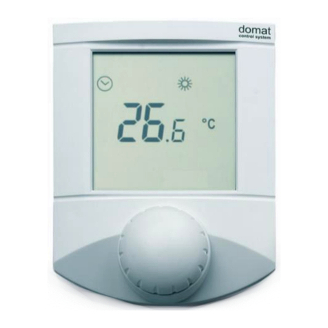
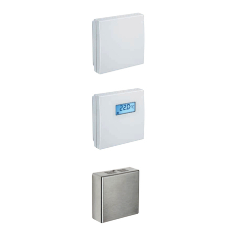
domat UI0 Series User manual

domat UI0xx 10/2017 Subject to technical changes. 1
UI0xx
Communicative room units and sensors
Summary
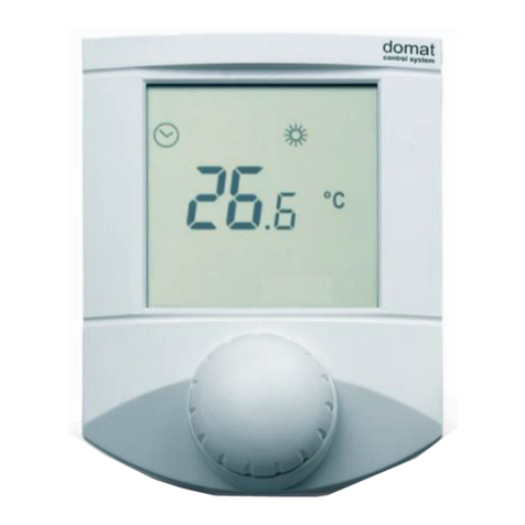
The UI...(BL) room unit is a family of universal communicative human-machine
interface for control of HVAC units and plants, and IRC controllers. The units
communicate over Modbus RTU / RS485 and they can be used as open system
components with majority of building control system and controllers. Compared to
the old series UI0xx, these types contain knob and display blue colour backlight
function and more accurate sensors of temperature and humidity.
According to production type, each version of the unit may contain display,
backlight, RTC nad IO, see type table below.
All versions of the room units now contain relative humidity measurement. UI04x,
UI06x and UI08x series have been replaced.
Application
▪systems with fancoils, convectors, floor and radiator heating, AHUs, air
conditioning units.
▪control of boilers, DHW, heating circuits, building controls in general
▪monitoring of room temperature and humidity
Function
The units acquire temperature and optionally relative humidity in the room, temperature
correction (knob) and required operation status which is set by push of the button or in
the menu. In the configurable menu following values can be set and displayed:
-temperature, actual temperature correction
-humidity (actual value only at room units containing the humidity sensor)
-time (only display at room units with RTC)
-basic setpoint - day
-basic setpoint - night
-outside temperature for heating enable
-DHW temperature
-heating curve type (1...4)
-operation mode (Residential with Day, Night, Time schedule, Off, or Hotel / Office
with Comfort, Standby, Party, Off)
-fan stage (Auto, Off, St.1, St. 2, St. 3)
-A/C mode (Auto, Heating, Cooling, Off, Fan only)

2 10/2017 Subject to technical changes. domat UI0xx
-weekly scheduler: 7 days, up to 6 events per day
-another 5 variables (air quality, fan speed etc.) –each has a profile where max.
and min. values, step, number of decimals, and symbol set are defined.
It is also possible to set / reset any of the LCD symbols on the display over Modbus.
The turn / push knob has three basic functions:
•instant edit (turning the knob) –settings of one predefined analogue value,
usually room temperature correction
•quick edit (short push) –change of predefined state, e.g. Presence (Comfort /
Standby / Off), Air condition (Auto / Heating / Cooling / Fan only / Off) etc.
•long push –jump to menu where values are listed by turning the knob, short push
selects the value to be edited, and the value is changed by turning the knob
followed by short push for confirmation.
After definable inactivity time, the display goes back to its basic state with rolling display
of selected values (e.g. actual temperature and humidity).
Backlight
function
UI0xxBL type contain knob and display blue colour backlight function. It is possible to set
brightness 0-100 % separately for knob and display. If user make some action with knob,
display and knob will shine for defined time. All of the backlight functions could be set
from Modbus master.
The unit Modbus address and functionality is defined over the RS485 interface with
service software ModComTool which is free for download at http://domat-
int.com/en/downloads/software. To interface the room unit to the computer use the
USB/485 converter M080, RS232/RS485 converter R012, or any suitable RS485 converter.
____________________________________________________________________
Technical data
Power supply
24 V AC +/- 20%, 1 W
Temperature measuring range
-20 ... 70 °C (accuracy ±1 ˚C)
Humidity measuring range
digital sensor 10 ÷ 90 %rH accuracy ±3%
Protection
IP20 (EN 60529)
Inputs (specific types only, see table below)
2x potential-free contact (dry contact) against G0,
24 V AC, 5 mA
Outputs (specific types only, see table below)
1x - 2x solid state relay, zero switching, for AC load
24 V AC, max. 0.4 A, AC1, general usage, non-
inductive load according to EN 60947-4-1,
galvanic isolation 1.5 kV
Setpoint
according to configuration, +/- 10 to +/- 1 K
Communication
RS485 - Modbus RTU, slave
selectable speed 1200 ... 115200 bps, parity and
bits are set in service SW
default 9600/N/8/1
The interface is optically separated 1 kV (except
for UI010 and UI010BL).
Display
LCD 60 x 60 mm, symbol set see above
domat UI0xx 10/2017 Subject to technical changes. 3
Terminals
recommended wire cross-section 0,14 –1,5 mm2
Cover
ABS, RAL9010, other colours optional
Weight
0,13 kg
Dimensions
90 x 115 x 30 mm, see below
Ambient conditions
According to DIN EN 60721-3-3. Climate class 3K5
(-5 to +45 ° C, 5% to 95% RH non-condensing
humidity)
Storage conditions
According to DIN EN 60721-3-1 Climatic class 1K3
(-5 to +45 ° C, 5% to 95% non-condensing relative
humidity).
Standards conformity
EMC ed.3 EN 61000-6-2: 2005, EN 55022 ed.3:
2010 (industrial environment)
Electrical safety EN 60950-1 ed.2: 2006 + A11:
2009 + A12: 2011 + A1: 2010 + A2: 2014 + Opr.1:
2012
Restriction of hazardous substances EN 50581:
2012
EU legislation
Council Directive 2014/35/EC, The Low Voltage
Directive (LVD)
Council Directive 2014/30/EC, Electromagnetic
Compatibility (EMC) Directive
Council Directive 2011/65/EC, RoHS2 Directive
Terminals
1
2
3
4
5
6
7
8
9
As seen when removing the display part.
The wiring goes towards the center of the
unit so that the cable can be brought
through the aperture in the middle of the
bottom part.
UI010(BL), UI0x1(BL)
1: NC not connected
2: NC not connected
3: K- communication RS485 -
4: K+ communication RS485 +
5: G0 power –common point
6: G0 power –common point
7: G power
8: -- connector not installed
9: -- connector not installed
UI0x2(BL)
1: DI1 input1
2: DI2 input2
3: DO1 output 1, 24 V AC against G0
4: NC not connected
5: G0 power, output –common point

4 10/2017 Subject to technical changes. domat UI0xx
6: G0 power, output –common point
7: G power
8: K- communication RS485 -
9: K+ communication RS485 +
UI020BL, UI0x5(BL)
1: DI1 input 1
2: DI2 input 2
3: DO1 output 1, 24 V AC against G0
4: DO2 output 2, 24 V AC against G0
5: G0 power, outputs, inputs –
common point
6: G0 power, outputs, inputs –
common point
7: G power
8: K- communication RS485 -
9: K+ communication RS485 +
Type table
Typ
LCD
Backlight
Knob
DI
DO
t
rH
RTC
UI010
✓
✓
-
-
✓
✓
UI010BL
✓
✓
✓
-
-
✓
✓
UI011
✓
✓
-
-
✓
✓
UI011BL
✓
✓
✓
-
-
✓
✓
UI012
✓
✓
2
1
✓
✓
✓
UI012BL
✓
✓
✓
2
1
✓
✓
✓
UI020
✓
✓
2
2
✓
✓
✓
UI020BL
✓
✓
✓
2
2
✓
✓
✓
UI051
✓
-
-
✓
✓
UI051BL
✓
✓
-
-
✓
✓
UI052
✓
2
1
✓
✓
✓
UI052BL
✓
✓
2
1
✓
✓
✓
UI055
✓
2
2
✓
✓
✓
UI055BL
✓
✓
2
2
✓
✓
✓
UI071
-
-
✓
✓
UI072
2
1
✓
✓
✓

domat UI0xx 10/2017 Subject to technical changes. 5
UI075
2
2
✓
✓
✓
Units without knobs are used as indicators, optionally with remote controlled inputs /
outputs. Process control algorithms (activating of the outputs by increased / decreased
temperature, humidity etc.) must be implemented in a master controller.
Installation
Units are intended for operating in ordinary and chemically non-aggressive environment.
They do not need any servicing or maintenance. Install them in a vertical position at
places where they can be operated easily and measure correct values of temperature and
humidity, i.e. in the height of about 150 cm, with no direct sunlight or other source heat
or cold (AHU outlets, refrigerator, electrical appliances). The device consists of two parts:
bottom with screw terminal block and top cover containing PCB, display, and the knob.
The bottom part is fixed by 2 or 4 screws to any flat surface or a flush-mounting box Ø 50
mm. There is an aperture for cabling in the back of the bottom part. The bottom should
be installed and cabling connected first, and the upper part inserted after the
construction works have been finished to prevent damage to the unit.
Seal the conduits to avoid influencing the sensor by draught. Use insulating pad when
installing the sensor on cold walls. Avoid sensor exposition to sunlight or other sources
of heat.
Opening the
cover
When removing the display part, proceed as follows:
-press gently the side parts of the unit and pull the right of the display part by
several milimeters
-pull the left of the display part
-pull the display part and remove it from the bottom.
Do not bend the display part too much, the connector pins could be damaged. The locks
are only at the sides of the display part, not at the top nor bottom.

6 10/2017 Subject to technical changes. domat UI0xx
Dimensions
All dimensions are in mm.
Display
Over Modbus, it is possible to set / reset
the complete symbol set except for the 7
segment digits, „Error“ and „Setting“ texts,
and symbols of °C, °F, %, and rH. Those are
part of the configurable menu profiles. The
register description is available in a
separate document Room units UI... –
Communication description.
LCD symbol set (see in the picture).

domat UI0xx 10/2017 Subject to technical changes. 7
DIP switches
Back of the PCB
BUS END: if ON, the bus is terminated (if
last device on the line)
USR: not used, reserved for future
applications
INIT: if ON on power-up, sets the
controller into default state and sets bus
address to 1, baud rate to 9600.
To set EEPROM into factory settings by
INIT, proceed as follows:
- connect the device over RS485 to a PC
with the ModComTool config tool
- set INIT to ON
- apply power (use only the connector
without bottom)
- find the controller in the tool (Scan)
- set INIT to OFF
- in the ModComTool, open the controller
window
- click the Init button in the tool
- remove and apply power
RoHS notice
The device contains a non-rechargeable battery which backups the real-time clock and
part of the memory. After the device is not operable, please return it to the manufacturer
or dispose of it in compliance with local regulations.
Safety note
The device is designed for monitoring and control of heating, ventilation, and air
conditioning systems. It must not be used for protection of persons against health risks
or death, as a safety element, or in applications where its failure could lead to physical or
property damage or environmental damage. All risks related to device operation must be
considered together with design, installation, and operation of the entire control system
which the device is part of.

8 10/2017 Subject to technical changes. domat UI0xx
Changes in
version
01/2017 —The first datasheet version.
03/2017 —Added picture and description of the installation. Corrected information
in table types.
07/2017 —Added non-backlight types –summary datasheet
10/2017 —Added Safety note
This manual suits for next models
16
Table of contents
Other domat Thermostat manuals

domat
domat UI090 User manual

domat
domat UC220 User manual

domat
domat UC100 User manual

domat
domat THERMASGARD RTM Repair manual

domat
domat THERMASREG FS-20 Repair manual

domat
domat UI0 BL Series User manual

domat
domat UI90 Series User manual

domat
domat UC120 User manual

domat
domat US100 User manual

domat
domat UI300 User manual
Popular Thermostat manuals by other brands

TOTALINE
TOTALINE 1 For All owner's manual

Honeywell
Honeywell RTH111 series Quick installation guide

Honeywell
Honeywell RTH1100 series operating manual

White Rodgers
White Rodgers 1F91W-71 installation instructions

Siemens
Siemens RDJ100 Operating and installation instructions

Elan
Elan EL-TSTAT-8820 Safety & installation instructions