4 03/2017 Subject to technical changes. domat UI09xx
The integrated temperature sensor range is -20 to +70 °C. Read and entered values are
available at the RS485 bus where a controller or SCADA reads them. The supervising
system can also write values to the unit (operation mode, fan stage, etc.), which are
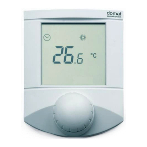
displayed on a large LCD display.
The CO2 measuring range is 0...5000 ppm. A range defined by two parameters is then
recalculated to 0...100 %, value, which is displayed on the LCD, e.g. 300...2500 ppm
displays as 100...0 % (of air quality) or 0...100 % (of air pollution). At the bus it is possible
to read the absolute value in ppm, too. The parameters are set through the
configuration software ModComTool or by direct writing into Modbus registers.
Default values are 0% ... 350 ppm (fresh air), 100 % ... 2500 ppm (maximum pollution).
Transportation and aging may cause sensor drift. The sensor records the lowest reading
and expects that at least once per 8 days the CO2level reaches the outside air
concentration (400 ppm). The lowest measured value is then assigned the 400 ppm
level. Autocalibration does not work if the room is occupied 24 hours a day, or there
are no periods when the gas level drops to background (e.g. greenhouses). Then, the
autocalibration function can be disabled through the configuration program or by
direct writing into the Modbus register. The autocalibration is set to on by default.
During the first days of operation, until the first autocalibration, the sensor may read
values which differ from the real values by several hundreds ppm, e.g. 200 ppm at
night etc. This error is automatically corrected with the first autocalibration.
The binary output (SSR), if available, may be controlled either from a PLC over the bus,
or configured as one of controllers:
•thermostat
•hygrostat (only at devices with rH sensor)
•controller switching at a predefined CO2level.
Setpoint and hysteresis are set over the bus. This function is not suitable for standard
integrated room control, it is to be used as supplementary only. The setpoints are not
influenced by operation modes (Day, Night, Off).
Units are intended for operating in a normal and chemically non-aggressive
environment. They do not need any servicing or maintenance. Install them in a vertical
position at places where they can be operated easily and measure correct values of
temperature and humidity, i.e. in the height of about 150 cm, with no direct sunlight
or other heat / cool source (AHU outlets, refridgerator, electrical appliances). The
device consists of two parts: bottom with screw terminal block and cover containing
PCB, display, and the knob. The bottom part is fixed by 2 or 4 screws to any flat surface
or a flush-mounting box Ø 50 mm. At the back of the bottom there is an aperture for
cabling. The bottom should be installed and cabling connected first, and the upper part
inserted after the construction works have been finished to prevent damage to the
unit.
Seal the conduits to avoid influencing the sensor by draught. Use insulating pad when
installing the sensor on cold walls. Avoid sensor exposition to sunlight or other heat
sources.
