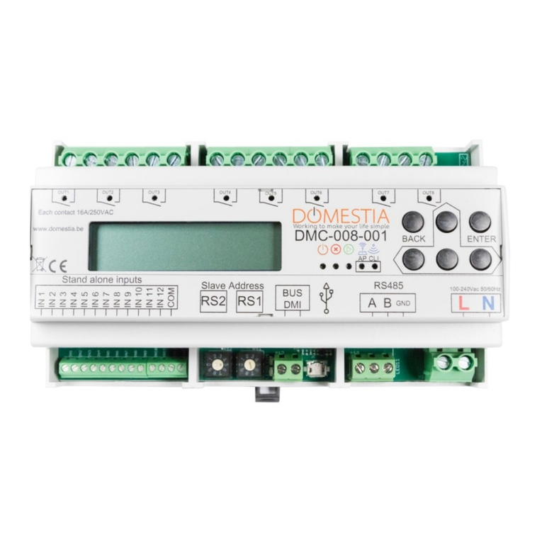
Domestia DMC-012-016 User manual

www.domestia.be
GEBRUIKSAANWIJZING
DMC/DKS-012-016 |
START KIT
O
N
/
O
F
F
O
N
/
O
F
F
O
N
/
O
F
F
O
N
/
O
F
F
O
N
/
O
F
F
O
N
/
O
F
F
START KIT
DMC/DKS-012-016
12 x

2
DMC-012-002
A B GND
10A
10A
A
B
C
D
E
*(1)
*(2)
1 2 3 4 5 6 7 8 9 10 11 12
100- 240 VAC / 50 – 60 H
Max 2A
2A 2A
LEFT RIGHT
UP
DOWN
Center
16A
Contact
10A
10A
10A
10A
8
A
8
A
8
A
8
A
8A 8A 8A 8A 8A 8A 8
A
8
A
Ph N
Ph N
Ph N
Ph N
Ph N
To identication
modules
(See Figure B)
RS485 to
other card(s)
(See Figure C)
FIGURE A - Motherboard DMC-012-016
FIGURE B - DMI-006-001 Module
DMI-006-001 D
UTP, VVT, VOB, XVB As chosen
For previous module
Or DMC-012-002
To following module(s)
*
Autorised star departure
*
Identification
Module
DMI-006-001
Isolate
the unused
inputs
Max.Lenght
Identification
Module
DMI-006-001
Identification
Module
DMI-006-001
Blue
Blue
Blue
Blue
Blue
Blue
Blue
Blue
Blue
Blue
Blue
Blue
Blue
Blue
Blue
Blue
Blue
Blue
Yellow
Yellow
Yellow
Black
Black
Black
Black
Black
Black
Max.Lenght
Max.Lenght
*
*
Isolate
the unused
inputs
Cable type (0.25, 0.8…)*
* Please always
respect the standards
in force of the RGIE
* it is advisable to place
the idencaon modules as close
as possible to the push buons

3
DMC-012-002
A
B
C
D
E
*(1)
1 2 3 4 5 6 7 8 9 10 11 12
Left Right
Up
Down
Center
8
A
8
A
8
A
8
A
8A 8A 8A 8A 8A 8A 8
A
8
A
DMC-012-002
A
B
C
D
E
*(1)
1 2 3 4 5 6 7 8 9 10 11 12
8
A
8
A
8
A
8
A
8A 8A 8A 8A 8A 8A 8
A
8
A
DMC-012-002
A
B
C
D
E
*(1)
1 2 3 4 5 6 7 8 9 10 11 12
8
A
8
A
8
A
8
A
8A 8A 8A 8A 8A 8A 8
A
8
A
DMC-012-002
A
B
C
D
E
*(1)
1 2 3 4 5 6 7 8 9 10 11 12
8
A
8
A
8
A
8
A
8A 8A 8A 8A 8A 8A 8
A
8
A
Ph N
Ph N
Ph NPh N
Do not connect
Card congured as master with 3 slaves Card congured as slave with address 2
Card congured as slave with address 3 Card congured as slave with address 4
To identication
Module
(See FigureB)
Do not connect
Do not connect
Left Right
Up
Down
Center
Left Right
Up
Down
Center
Left Right
Up
Down
Center
FIGURE C - Linking DMC-012-016 cards - Example of 4 card connection
1. INSTALLATION
At the start of the motherboard, the DMI-006-001 modules are interwired using a twowire
cable without polarity. They can be wired in a variety of ways, either as bus-wired,
start-wired or both ways simultaneously.
If your installaon has more than one card, please refer to point 3 of this manual.
The system will enable you to manually (using 5 buons) program () the 12
motherboard outputs and to program the funcons explained below.
This funcon simulates a tradional command. When you press the pushbuon (PB) once,
the contactor is acvated and the power is sent to that output.
A second press on the (PB) shuts o the power to that output.
This funcon simulates the contact of a tradional PB. As long as you press the PB, the output is acve. Can

also manage signals from detectors.
This funcon simulates a mer. When you press the PB once, this output is acve for the programmed
length of me. However, the mer can be stopped before the end of the programmed me by pressing the
PB again. In the same context, Push and hold 3.
By pressing on a PB anywhere on the installaon, this funcon allows all the points or a selecon of certain
points to be switched on.
By pressing on a PB anywhere on the installaon, this funcon allows all the points or a selecon of certain
points to be switched o.
This funcon allows certain selected lights to be switched on and o during a prolonged absence.
The simulaon is carried out by pressing the PB programmed for this purpose.
The outputs are acvated in a random order, both in terms of choice and duraon.
This funcon allows 4 groups to be created. One pression on a PB associated to a group where a point is lit
switches o the whole group. One press on a PB associated to a group where no point is lit, acvates the
sending of power to the whole group.
If an installaon has more than 12 outputs (i.e. more than one DMC-012-016 card), you will have to inter-
connect the cards as described in .
The factory default conguraon of the DMC card is for it to operate alone, without slave(s). You must
change the funcons of the cards in order to use several DMC cards.
Here is an example of an installaon with 48 outputs, i.e. 4 cards
In this example, one card must be congured as the master and the other three as slaves. The master card
manages outputs 1 to 12 and runs the slave cards.
N.B.: There can only be one master card connected to the bus per installaon!3.1. Steps to be followed to
congure the master card

5
I. Switch o the electricity supply to the master card.
II. Hold the RIGHT buon down while switching on the power supply to the card. LEDS
should light up: If that does not happen, use the UP and DOWN buon unl LEDS A, B and E are
lit up.
III. Using the RIGHT and LEFT buons and LEDS 1 to 4, select the number of outputs you have on
the installaon (in this example 4 cards).
1 from 1 to 12
1, 2 from 1 to 24
1, 2, 3 from 1 to 36
1, 2, 3, 4 from 1 to 48
IV. Validate using the CENTER button.
I. Switch o the electricity supply to the slave card to be programmed.
II. Hold the DOWN buon down while switching on the power supply to the card. LEDs
should light up: If that does not happen, use the UP and DOWN buon unl LEDS are
lit up.
III. Using the RIGHT and LEFT buons and LEDS , select the range of outputs you want to have
for this card ().
1 from 1 to 12
2from 13 to 24
3 from 25 to 36
4 from 37 to 48
IV. Validate using the CENTER buon.
Repeat the operaon for each slave card.
N.B.: If LEDs are lit up and LED 1 is blinking, there is a communicaon error: the
master card is not accessible! Please check that you have a congured master card in the installaon
and the Bus RS 485 is correctly connected ().
Details on how to recongure a master card are set out in

Press once on the DOWN buon in order to start programming the outputs and idencaon modules.
Led 1 (1st relay) is blinking.
You can select the programming mode by pressing on the UP and DOWN buons on any card. (
).
• LEDS AE lit = Funconal Mode
• LEDS BE lit = Remote Control Switch Mode
• LEDS CE lit = Relay Mode
• LEDS DE lit = Timer Mode
• LEDS BCDE lit = Switch All On or Select Mode
• LEDS BDE lit = Switch All O or Select Mode
• LEDS CDE lit = Presence Simulaon
• LEDS BCE lit = Group
Select the output by pressing the LEFT and RIGHT buons on any card.
Switch on or o the power supply to the relevant output by pressing on the CENTER buon of any card.
Once you have chosen the Relay or Remote Control Switch mode, use the RIGHT and LEFT buons to
choose the output and validate it by pressing the CENTER buon once the choice has been made. The LED
of the chosen output should no longer be blinking.
You then have to go to the room in queson and press on the PB that runs this output. By pressing on the
selected push buon, the power supply is interrupted momentarily at that point, which means that the
addressing is recorded. Repeat the operaon for each push buon that you want to associate to that same
point.
When you have selected all the PBs running this output, the addressing is recorded. You can then move on
to the next output and repeat the operaon.
To leave the Relay or Remote Control Switch mode, press the CENTER buon and then the UP buon as
may mes as necessary to return to the OPERATING mode
(LEDslit).

7
The Timer mode programming is idencal to the Remote Control Switch programming mode. To access it,
press the DOWN buon in Operang mode unl LEDs are lit.
If you want to change the me of the mer at the validated output, press once on the DOWN buon to
programme it. are lit by default, which means that the mer is programmed
for 127 minutes and 30 seconds.
Use the RIGHT and LEFT buons to change the me. The following table sets out the me value of the
LEDs. The mes are cumulave.
1 30 seconds
21 minute
3 2 minutes
4 4 minutes
58 minutes
6 16 minutes
7 32 minutes
864 minutes
Press on the UP buon to validate the programmed me.
For example: If you want to programme a light point to be on for 6 minutes and 30 seconds, light up LEDs
To leave the Timer mode, press the CENTER buon and then the UP buon as may mes as necessary to
return to the OPERATING mode (LEDs lit).
Starng from the Operaonal mode (LEDs lit), press on the DOWN buon unl LEDs
are lit. Then validate using the CENTER buon to acvate the outputs.
You then have to go to the room in queson and press on the PB that should switch on everything.
By pressing on the selected push buon, the power supply is interrupted momentarily at that point,
which means that the addressing is recorded. Repeat the operaon for each push buon that you
want to combine at that same point.
To leave the Switch All On mode, press the CENTER buon and then the UP arrow as may mes as
necessary to return to the OPERATING mode (LEDs A and E lit).

Starng from the Switch All On mode (see above), press once on the DOWN buon when all the
outputs are acvated. At that me, LEDs are lit, together with all the LEDs from the
previous conguraon (by default: all).
Use the LEFT and RIGHT buons to choose the outputs. Press on the CENTER buon to select or
deselect an output.
To leave the Select Mode, press once on the UP buon to return to the Switch On All mode.
Programming the Switch All O mode is idencal to programming the Switch All On funcon. To access it,
press the DOWN buon in Operang mode unl LEDs are lit.
You then have to go to the room in queson and press on the PB that should switch on everything. By pres-
sing on the selected push buon, the power supply is interrupted momentarily at that point: which means
that the addressing is recorded. Repeat the operaon for each push buon that you want to combine at
that same point.
If you want to add or remove certain simulaon points, press once on the DOWN buon when all the
outputs are acvated. At that me, LEDs are lit, together with all the LEDs from the previous
conguraon (by default: all). Use the LEFT and RIGHT buons to choose the outputs. Press on the CENTER
buon to select or deselect an output.
To leave the points selecon, press the UP buon once.
To leave the Presence Simulaon mode, press the CENTER buon and then the UP arrow as may mes as
necessary to return to the OPERATING mode ().
Starng from the Operaonal mode (LEDs lit), press on the DOWN buon unl LEDs are
lit and that LEDare blinking which corresponds to the number of the group. Then validate
using le to right, then the CENTER buon to acvate the outputs.
You then have to go to the room in queson and press on the PB that runs this group. By pressing on the
selected push buon, the power supply is interrupted momentarily at that point: which means that the
addressing is recorded. Repeat the operaon for each push buon that you want to associate to that same
group.
Press once on the DOWN buon to add certain points to or remove them from the selected group. At this
me, LEDs are lit, together with all the LEDs from the previous conguraon (by default: all).
Use the LEFT and RIGHT buons to choose the outputs. Press on the CENTER buon to select or deselect
an output. To leave the points selecon, press the UP buon once.
To leave the Group mode, press the CENTER buon and then the UP arrow as may mes as necessary to
return to the OPERATING mode (LEDs lit).

9
• Power supply: 100-240VAC/50-60Hz.
• Number of outputs per card: 12 unipolar contacts of 16A free of potenal and removable.
• Idencaon module bus: 10 VDC on 2 non-polarised wires.
• Communicaon bus: RS485.
• 5 buons for programming.
• 2 black wires: Non-polarised bus.
• 6 blue wires: Potenal free inputs.
• 1 yellow wire: Common.
• Module idencaon: Automated idencaon when acvated.
• Idencaon module wiring: 2 non-polarised wires VVT, XVB, VOB, … (Check the quality of the
connecon: the secon of the idencaon module wires is 0.6mm²).
• RS485 link between cards in a single box: use VVT, VOB, UTP,… wires.
• RS485 link between dierent cards in dierent boxes: use UTP wires (one pair for A and B and
one pair for GND).
• Do not exceed a 1.5mm² secon for communicaon terminals. Do not exceed a 4mm² secon
for power terminals.
• “Module bus” cable: With respect to the maximum length of this bus and the secon of the
cable to be used, the modules use maximum length of this bus and the secon of the cable to be
used, the modules use current and the maximum resistance.
This product has undergone a series of laboratory tests to ensure it meets the stand-ards included
in point 8. The following rules must be respected so ensure compliance with those standards:
• Do not roll the bus cables (idencaon bus modules and communicaon bus) into a loop.
• Do not exceed the maximum power of 8A per output contactor.
• In case of a high inductance load, place a contactor parallel to the element in queson.

• The DMC-012-016 kit is designed to be placed in an electrical box with a DIN rail.
• Make sure you place the electrical box containing the kit so that it is not in direct sunlight. Do not
place the box above a heat source (e.g.: radiator). Make sure that there is natural venlaon for the
DMC-012-016 card.
Failure to respect the above points results in electrical risks and a loss of guarantee.
The basic warranty for your product is 2 years from the date your order is received.
Please make sure you keep your invoice, with the serial number safely, as it is the only document that acts
as a guarantee in case of any problem.
• Damage caused by inappropriate use, incorrect use, poor maintenance or notrespecng the
instrucons given by the manufacturer. Aempted repairs by the customer or by a non-
authorised third party. Damage caused by accidents, force majeure or other causes for which
Domesa may not be held responsible.
• Any fault other than from the correct operang or good use of the material.
• EN 55022 class B emission.
• 30-1000MHz radiated emission.
• 230V 150k-30MHz AC conducted emission.
• Disturbing current emission on the 150k-30MHz bus (current tester).
• EN 61000-3-2 Harmonic emission to 2kHz.
• EN 61000-3-3 icker emission.
• EN 61000-4-2 8kV/air electrostac discharges (insulator part = casing) in criteria B.
• EN 61000-4-3 immunity test on RF 80MHz-2GHz 10V/m elds in criteria B.

• EN 61000-4-4 2kV burst in criteria B.
• EN 61000-4-5 2kV shock wave between phase and earth, 1kV between phases, all in criteria B.
• EN 61000-4-6 induced signals due to RF 150kHz-80MHz 3V elds in criteria A or 10V in criteria B.
• EN 61000-4-11 70%U voltage variaons during 3 x 0.3s, then 0%U during 3 x 0.1s in criteria B.
• EN 61000-4-4 0.5kV burst in criteria A via capacive clamp.
• EN 61000-4-6 induced signals due to RF 150kHz-80MHz 3V elds in criteria A or 10V in criteria B.
• 1996 EN50090-2-2 + A1 2002.
• EN 60664 - 1 circuit insulaon.
11

12
rue Jean Jaurès, 176
4430 Ans
Belgium
+32 4 372 07 16
+32 4 372 07 19
This manual suits for next models
3
Table of contents
Other Domestia Network Hardware manuals