manuals.online logo
Brands
  1. Home
  2. •
  3. Brands
  4. •
  5. Dometic
  6. •
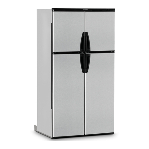
  7. Refrigerator
  8. •
  9. Dometic RM2310 Manual

Dometic RM2310 Manual

I
81Dometic
SERVICE OFFICE
The Dometic Corp.
509 S. Poplar St.
LaGrange IN 46761
CANADA
Dometic Distribution, Inc
866 Langs Drive
Cambridge, Ontario
CANADA N3H 2N7
ABSORPTION REFRIGERATOR
FOR LP-GAS AND ELECTRIC OPERATION
WARNING
This unit must be serviced by an
authorized serviceman. Modification
of the appliance can be extremely
hazardous and could lead to serlous
Injury or death.
INDEX
Page
Installation.
..............
2
Operation.
.............. .8
Maintenance and
Service
...............
10
AVIS
CETAPPAREIL DOIT ~TRE F&PARC
SEULEMENT PARUN RCPARATEUR
AUTORISk MODIFICATION DE
CAPPAREIL P~URRAIT ETRE
EXTRkMEMENT DANGEREUSE, ET
POURRAIT CAUSER MAL OU MORT.
INSTALLATIONAND
MODEL
OPERATINGINSTRUCTIONS
RM2310
I
FormNo. 3103619.007
01991 The DometicCorp.
LaGrange IN 46761
IMPORTANT INSTRUCTIONS
READ CAREFULLY
in the vicinity of this or
anyother
SECTION A. INSTALLATION
1. General Instructions
This appliance isdesigned for storage of foods and
storage of frozen foods and making ice.
The refrigerators outlined herein have been design
certified byA.G.A. under the ANSI 221.19 Refrigerator
Standard for installation in a mobile home or
recreational vehicle and are approved bythe Canadian
Gas Association.
The certifications are, however, contingent on the
installation being made in accordance with the
following instructions as applicable.
In the U.S.A., the installation must conform with:
1.
2.
3.
National Fuel Gas Code ANSI 2223.1 (latest
edition).
Manufactured Home Construction and Safety
Standard, Title 24 CFR, Part 3280
Recreational Vehicles ANSI Al 19.2 (latest
edition).
The unit must be electrically grounded in accordance
with the National Electric Code ANSI/NFPA 70 (latest
edition)when installed ifan external alternating current
electrical source is utilized.
4. Any applicable local code.
In Canada, the installation must conform with:
1
.
Current CGA B 149 Gas Installation Codes
2. Current CSA Standard Z 240.4 Gas-Equipped
Recreational Vehicles and Mobile Housing
3. Any applicable local code.
The unit must be electrically grounded in accordance
with the Canadian Electrical Code C22 Parts 1and 2.
2.
Ventllatlon
The installation shall be made in such a manner as to
separate the combustion system from the living space
of the mobile home or recreational vehicle. Openings
forairsupply orforventing ofcombustion products shall
have a minimum dimension of not lessthan l/4 inch.
Proper installation requires one lower fresh air intake
and one upperexhaust vent. The ventilation kitsshown
in this instruction manual have been certified for use
with the refrigerator models listed in the table.
For
certified vent system kits, see separate list.
The
ventilation kits must be installed and used without
modification. An opening toward the outside at floor
level inthe refrigerator compartment must be provided
for ventilation of heavier-than-air fuel gases. The lower
vent of the recommended kits is provided with proper
size openings. The flow of the combustion and
ventilation air must not be obstructed.
The lowerside vent isfitted with apanelwhich provides
an adequate access opening for ready serviceability
of the burner and control manifold of the refrigerator.
3.
Certlfled lnstallatlon
Certified installations require one roof vent and one
lower side vent.
For Certified vent system kits, see separate list.
For further information, contact your dealer or
distributor.
4.
Methods of lnstallatlon
The methods of installation are shown in Fig. 1A and
1B. Itisessential that all maximum or minimum dimen-
sions are strictly maintained asthe performance ofthe
refrigerator is dependent on adequate flow of air over
the rear of the refrigerator.
Fig. 1A
Ventilation
height
5. Ventllatlon helghts
Refer to Fig. 1A and 1B, Page 2.
Minimum ventilation heights in inches and mm
Refrigerator Installation with Installation with roof
Model upper and lower vent and lower side
side vent vent
inch 37 31
RM2310mm 940 787
6. Clearances
Minimumclearances ininchesto combustible materials
are: G: Top 0”
K: Side 0”
L: Bottom 0”
M: Rear 1”
N: Ventilation Height
NOTE: Clearance “M/l” isbetween the rearmost partof
the refrigerator and the wall behind the refrigerator.
NOTE:Clearance “N” isthe distance betweenthe bot-
tom ofthe lowerventtothe roofmaterial. Forventilation
height, refertoSectionA. Installation, /fern5. Ventilation
Heights. See Fig. 2.
Fig. 2 G
7. lnstalllng refrlgerator In enclosure
NOTE: DO NOT install the appliance directly on
carpeting. Carpeting mustbe removed or protected
by a metal or wood panel beneath the appliance,
whichextends at leastthefullwidth anddepth ofthe
appliance.
The refrigerator must be installed in a substantial
enclosure and must be level. When installing the
refrigerator inthe enclosure,
be certain
there isacom-
pletesealbetween
the
frontframeofthe refrigeratorand
the top, sides and bottom ofenclosure. A length ofseal-
ingstrip isapplied to the rear surface ofthe front frame
for this purpose. Also apply a sealing strip to the
foremostfloorofthe enclosure and applyasecond seal-
ingstrip to the bottom ofthe trim strip onthe front base
asshown inFig.3.The sealingshould providecomplete
isolationofthe appliance’s combustion systemfromthe
vehicle interior.
Fig. 3
Sealing strip applied
to
bottom of trim strip
front of compartment floor
Becareful notto damage the sealing strip applied to the
floor of the enclosure when the refrigerator is put in
place.
The refrigerator issecured inthe enclosure with eight
screwsand they mustbeinstalled inthe following order:
The first six screws are installed on the front frame,
andthe lasttwoscrews installed inthe rearbase. Failure
to follow the sequence in securing refrigerator in
enclosure can cause leakage between the frame and
cabinet. (See Fig. 4, Page 4).
Any
space betweenthe counter, storage areaor ceiling
and top ofthe refrigerator should beblocked. The heat
produced atthe rearofthe refrigeratorwillbecometrap-
ped inthisspace, making the top ofthe refrigerator hot
and reduce the efficiency of the refrigerator.
-3-
Fig. 4
2 nd
The dimensions shown in
the Table
belowwillgiveyou
adequate spaceforserviceand proper installation. See
Fig. 5.
8.
Gas connection
Hook up to the gas supply line accomplished at the
manualgasshutoff valve,which isfurnished witha3/8”
SAE (UNF 5/8”
-
18) male flare connection. All com-
pleted connections should bechecked for leaks with a
non-corrosive leak detector. (See Fig. 6)
WARNING
DO NOT USE A FLAME TO CHECK
FOR GAS LEAKS.
Fig. 5
The gas supply system must incorporate a pressure
regulatorto maintain asupply pressureofnot morethan
11 inches water column.
LP GAS
CYLINDER
REGULATOR
REFRIGERATOR
VIEW FROM ABOVE
Refrigerator
model Overall Installation Recess Distance between
dimensions dimensions dimensions top of condenser
and top of
Height Width Depth Height Width Depth Height Width Depth
A B C h
W
d H W D refrigerator
e
inch 30-318 21-11116 22-l/16 29-9116 20-l 14 20-316 29-314 20-l 12 21-318 l-114
RM2310 mm 771 551 560 751 514 517 756 521 542 32
-4-
Fig. 6
MODEL RM2310 .
C. Closethe gas
valve
byturning the knob
“A”
back
to
“OFF”
position. (See Fig. 7)
BLOCK FOR
HEATING
ELEMENT
When testing the gas supply system at test pressures
inexcess of l/2 psig the refrigerator and its individual
shutoff valvemustbedisconnected fromthe gassupply
piping system.
Removeburner coverplate. (SeeFig.6).Open the
gasvalve byturning knob
“A”
to position “GAS”
without pushing the buttons “C” and
“D”. (See
Fig. 7). Apply commercial leak check bubble
solution to the burner jet. (See Fig. 8). Be careful
not to damage the burner jet.
Fig. 8
Clear Blue Color of Flame
When testing the gas supply system at pressures less
than orequal to l/2 psigthe appliance mustbeisolated
from the gas supply piping by closing its individual
manual shutoff valve.
A
Incasedetailed instructionson the installation and con-
nection to the gas supply are required, contact your
dealer or distributor.
Thermocouple
RM2310
9. Gas safety shutoff
Connection Spring Thermocouple
The gas safety shutoff must be tested after the
refrigerator is connected to the LP Gas supply.
To test the gas safety shutoff, proceed as follows:
H
Refrigerator with Piezo lgnitor
REFRIGERATORS WITH PIEZO
IGNITORS
D.
E.
Wait one (1)minute.
A.
B.
_
Start the refrigerator according tothe instructions
for gas operation with piezo ignitor. See Section
8. Operating Instructions, kern 3. Gas Operation.
I
Burner jet
Check that the gas flame is lit. This can be
observed through reflector
“E”. (See
Fig. 7)
F. No bubble should appear at the opening of the
burner jet. Bubbles indicate
a
defective gas safety
shutoff and service is required.
G. If no bubbles were present at the burner jet, rinse
the orifice with water. Replace the burner cover
plate. Start the refrigerator by following the
instructions for gas operation with piezo ignitor.
See Section B. Operating Instructions, /tern 3,
Gas
Operation.
Normal gas operation should occur.
Allow the burner to
operate
for a minimum of five
(5) minutes.
FOR GAS LEAKS.
WARNING
DO NOT USE A FLAME TO CHECK
L
10.
120
volt AC connection
The refrigerator is equipped with a three prong
(grounded) plug for protection against shock hazards
and should be plugged directly into a
properlygrounded
three-prong receptacle.
DO NOT
cut off or remove the
grounding prong from this plug. The free length of the
cord is 2 feet and therefore recommended that the
receptacle be located to the left side of the refrigerator
(viewed from the rear) and approximately6
inches from
the floor. (See Fig. 9). This allows easy access through
the vent door. The cord should be routed to avoid
contacting the burner cover, flue cover, or any other
components that could damage the cord insulation.
120 Volt AC
fib receptacle
11.
12
volt DC connection
n
3-WAY REFRIGERATOR MODEL
The 3-way model has a 12-volt DC terminal block
located under a plastic cover on the back of the
refrigerator for the refrigerator heater. (See Fig. 6)
The refrigerator must be connected by a separate
curcuit to the battery with two wires of adequate
capacity to avoid voltage drop when the 12 volt DC
heater is being operated. The wire gauge should be
chosen with consideration to the length, refer to the
Table below for wire size. The 12 volt DC circuit must
be fused; refer to the Table below for fuse size.
DO
NOT
use the body or chassis of the vehicle as a
substitute for either ofthe two conductors. DONOT
connect any other electrical equipment or lighting
to the refrigerator circuit.
MAXIMUM TOTAL CONDUCTOR WIRE LENGTH IN FEET/METERS
MAX.
FUSE
MODEL AWG SIZE
14 12 10 8
17ft. 27 ft. 43ft.
RM2310 loft.
3m 5.2 m 8.2 m 13m 15 amps
CAUTION
DONOT operate the refrigerator on 12volt DCwhen
the
vehicle isparked. The amperage draw of the 12
volt DC heating element can discharge a battery in
a very short time. The installation of a 12 volt DC
operated refrigerator requires a relayto be installed
on the tow vehicle or inthe caravan. The relay will
automatically shut off the 12 volt DC power to the
refrigerator when the ignitionisturned off. (See Fig.
10).
RELAY
%
7
BAllERY
Fig. 10
6-
12. Changingdoor hingesfrom onesideto the other
(Refer to Figure 11)
A.
B.
C.
D.
E.
F.
G.
Remove the top hinge pin and lift out the door.
Remove lower hinge pin (including washers)and
relocate them to the hole on the opposite side
hinge.
Unscrew the travel latch and relocate it on the
opposite side.
The bushing and the latch retainer on the top of
the door should be reversed.
Replace the door back on the refrigerator and
install the top hinge pin.
Remove the door handle and refasten it on the
opposite side. Insertthe plastic caps (found inthe
miscellaneous parts bag)intothe screw holes left
open on the door.
Checkthe doorto determine ifitopens and closes
easilyand the gaskets sealonallsides; also make
sure the travel catch operates properly. If
adjustments are required, remove the plastic
cover snapped overthe top hinge, loosen the two
screws and reposition the door. Tighten the
screws and replace the plastic cover.
e
Relocatkavel
latch to opposite side p
I \
0
Replace door and
install top hinge pin
i
13. Instructions for mounting the door panel
The refrigerator is normally delivered without door
panels(s).Beforestarting the mounting work, check the
paneldimensions forcompliance withthose given inthe
Table below,and readthe instructions thoroughly. (See
Fig. 12).When mounting the panel, proceed
as
follows:
A.
B.
C.
D.
E.
F.
The decoration strip(s) are taped inside the door.
Ifinstalledonthedoor, removethedoordecoration
strip (2)by removing its two screws (1).
Insertoneofthe vertical edges ofthe panel intothe
groove of the door frame (3).
Bend the panel gently so that the free side of the
panel can be slipped into the corresponding
groove of the door frame (4).
Slidethe panel down intothe groove ofthe bottom
frame (5).
Between the upper edge ofthe panel and the door
frame there isa gap which should be covered by
the decoration strip.
Putthe decoration strip acrossthe door sothat the
gap iscovered and push upward (6).The tabs on
the insideofthe strip should fit inbehind the flange
ofthe door frame. Secure the decoration stripwith
the two screws removed in Step A(1).
PANEL DIMENSIONS
MAX. THICKNESS 5/32” (4mm)
Relocate
$4 hinge pin
washer
lower
and
Move
door
handle to
opposite
side
0
, Reverse bushing
and latch retainer
-7-
Fig. 12
SECTION B. OPERATION
1. Importance of leveling a refrigerator
In an absorption refrigerator system, ammonia is
liquified in the finned condenser coil at the top rear of
the refrigerator. The liquid ammonia then flows intothe
evaporator (inside the freezer section) and isexposed
to acirculating flow of hydrogen gas, which causes the
ammonia to evaporate, creating a cold condition inthe
freezer.
The tubing inthe evaporator section isspecifically
sloped to provide a continuous movement of liquid
ammonia, flowing downward by gravity, through this
section. Ifthe refrigerator isoperated when it isnot level
and the vehicle is not moving, liquid ammonia will
accumulate in sections of the evaporator tubing. This
willslowthe circulation of hydrogen and
ammonia gas,
or in severe cases, completely block it, resulting in a
loss of cooling. Any time the vehicle is parked for
several hours with the refrigerator operating, the
vehicle should beleveledto preventthis lossofcooling.
The vehicle needs to be leveled only so it is
comfortable to live in (no noticeable sloping of floor or
walls).
When the vehicle is moving the leveling is not
critical, as the rolling and pitching movement of the
vehicle will pass to either side of level
-
keeping the
liquid ammonia from accumulating in the evaporator
tubing.
2.
Controls
Refrigerators with Piezo lgnitors
A. - ON/OFF Switch
B. - Thermostat Gas/Electric
C. - Safety Push-button
D. - Piezo lgnitor
E. - Flame View Port
3. Gas Operation
A. To start the refrigerator, turn knob
“A”
to the
“GAS” position. (See Fig. 13).
B. Turn the thermostat knob
“B”
one quarter (l/4)
of a turn from the “OFF” position. (See Fig. 13).
C. Push button “C” in until it bottoms out
-
and
hold. While holding button “C”, push button
“D”
for the piezo ignitor several times to light the
burner. This can be observed through the flame
view port,
“E”,
on the refrigerator. (See Fig. 13).
D.
E.
After
the
flame lights, continue to hold button “C”
for an additional ten (10) seconds. Release the
button “C” and check the flame view port
“E”
to
makesurethe burnerdoes notgoout. Ifthe burner
goes out, repeat the lighting procedure Steps A.
through D.
Toshut off the refrigerator, turn Knob
“A”
to the
“OFF” position.
4.
Electric operation
A.
B.
P
Check to be sure the power cord is properly
connected tothe power supply. (See Fig.9).Ifthe
refrigerator isequipped for 12volt DCoperation,
the tow vehicle or caravan engine should be
running to prevent discharging the battery.
Turn Knob “A” to the position marked
“ELEC”
for 120volt AC operation or
“12V”
for 12volt DC
operation. (See Fig. 13).
Turn the thermostat Knob “6” one quarter (l/4)
“r
of a turn from the “OFF” position.
D. To
shut offthe refrigerator, turn Knob “A”
to the
“OFF” position.
5. Thermostat
The refrigerator isequipped with athermostat that can
be adjusted byturning knob “6” to a different setting
to maintain the desired cabinet temperature (See Fig.
13).
A
B.
C.
“OFF” Setting of the Thermostat: In gas
operation, the thermostat closes its main valve
and the burner runs continuously at the bypass
rate or pilot. In electrical operation, the contacts
in the thermostat are open and the heating
elements are off.
“MAX” Setting of the Thermostat: In gas
operation the thermostat allows the burner to
remain on high flame continuously. In electric
operation, the heating element is “ON”
continuously.
The thermostat can beadjusted between “MAX”
and “OFF” to obtain the desired cabinet
temperature. The closer the knob isto “MAX” -
the colder thecabinet temperature. The closerthe
knob is to “OFF” - the warmer the cabinet
temperature.
When the thermostat reaches the set
temperature, itwill cut the burner back to bypass
or, in electric operation, shut off the heating
element.
The setting ofthe thermostat isnotcritical, butwe
recommend it be adjusted to maintain adry frost
on the cooling fins. Adjust the thermostat knob
closer to “MAX” when the outside temperature
becomes warm.
6.
How to use the refrigerator
A. Food Storage Compartment
The food storage compartment is completely
closed and unventilated, which is necessary to
maintain the required low temperature for food
storage. Consequently, foods having a strong
odor or those that absorb odors easily should be
covered. Vegetables, salads, etc. should be
covered to retain their crispness.
The coldest
positions in the refrigerator are under the cooling
fins and at the bottom of the refrigerator. The
warmer areas are on the upper door shelves. This
should be considered when placing different types
of food in the refrigerator.
One-half of the lower door shelf is equipped
with fingers. The fingers are designed to prevent
largecontainers(half-gallonof milkorjuice)from
shifting or spilling while traveling.
B. Frozen Food Storage Compartment
Place
quick frozen
soft fruits and ice cream in the
coldest part of the freezer compartment, which is
at the bottom of the aluminum liner. In models with
a shelf, place these foods on or just below the
freezer shelf. Frozen vegetables may be stored in
any part of the freezer compartment.
This compartment is not designed for the
deep or quick freezing of food. Meat or fish,
whether raw or prepared, can be stored in the
frozen food storage compartment provided it is
first pre-cooled in the refrigerator. It can be stored
about three times longer in the frozen food
compartment as compared to the fresh food
compartment. To prevent food from drying out,
keep it in covered dishes, containers, plastic bags
or wrapped in aluminum foil.
C. Ice Making
Ice cubes can be made in the tray. Fill tray with
water to within l/4 inch @mm) from the top. For
faster ice making, place the tray in direct contact
with the freezer shelf.
To release the ice cubes, hold the tray with
both hands and twist the tray. Preferably, unused
cubes should be replaced in the tray. Refill the tray
with water and place the tray on the freezer shelf.
-9-
Ice making is accelerated if the thermostat knob
“B”
is turned to the
“MAX”
setting. It is a good
idea to do this a few hours before you require ice.
Be sure to turn the thermostat back to the normal
setting when the ice is formed. Food in the lower
compartment can be frozen ifthe thermostat is left
on
“MAX”.
D. Defrosting
Shut off the refrigerator by turning knob
“A”
to
“OFF” position. Empty the refrigerator, leaving
the drip tray under the finned evaporator. Leave
the cabinet and freezer doors open. Defrosting
time can be reduced by
filling
the ice
tray
with hot
water and placing it on the freezer shelf. When all
the frost has melted, empty the drip tray and dry
the interior of the refrigerator with a clean cloth.
Replace the drip tray and ice tray. Replace all the
food and set the thermostat to its normal position.
CAUTION
DONOT use a hot air blower as permanent damage
could resultfromwarping the metalor plastic parts.
DO NOT use a knife, ice pick or other sharp tools to
removefrostfromthe freezer shelf. They can create
a leak in the ammonia system.
E. Cleaning
To clean the interior lining of the refrigerator, use
lukewarm, weak soda solution. The evaporator,
ice trays and shelves must be cleaned with warm
water only. It is important to always keep the
refrigerator clean.
NEVER USE STRONG CHEMICALS OR
ABRASIVE CLEANING MATERIALS ON ANY
PART OF THE REFRIGERATOR.
7. Shut-off/Storage Procedure
To shut off the refrigerator, turn knob
“A”
to “OFF”
position. Ifthe refrigerator will not be in operation for a
period of weeks, you should empty, defrost and clean
it; and leave the doors ajar. Dry the ice tray and keep it
outside the cabinet.
SECTION C. MAINTENANCE AND SERVICE
1. Perlodlc maintenance
To keep your Dometic refrigerator operating efficiently
and safely, periodic inspection and cleaning of several
components is recommended once or twice a year.
A.
B.
It is important to keep the area at the back of
the refrigerator clear. Check the lower vent, upper
vent and the area between these openings for any
obstructions such as bird/insect nests, spider
webs, etc. It is important to keep the refrigerator
area free from combustible material, gasoline and
other flammable liquids or vapors.
Check all connections in the LP gas system (at
the back of the refrigerator) for gas leaks. The LP
gas supply must be turned on. Apply a non-
corrosive bubble solution to all LP gas
connections.
WARNING
DO NOT USE A FLAME TO CHECK
FOR GAS LEAKS.
C. Check burner flame for proper appearance. The
flame should be light blue with
no
yellow
at the tip.
Fig. 14
-
10 -
Fig. 15
Thermocouple
.
connedIon’
\
I /
TEST
PORT
CAUTION CAUTION
Thefollowingmaintenance isrequiredonce ortwice DO NOT use awire
or
pinwhen cleaning the burner
a year, but should only be done by a qualified jet as damage can occur to the precision opening.
servicemanwho isfamiliar with LPgassystemsand This can cause damage to the refrigerator or create
refrigerators. a fire hazard.
D.
E.
Check Gas Pressure
The LP gas pressure should be checked and
readjusted if necessary. The correct operating
pressure is eleven inches of water column. The
correct placetotake the pressure reading isatthe
test port just ahead of the main orifice. (See Fig.
15).
Cleaning Flue Tube, Burner and Burner Jet
NOTE: Before working on the refrigerator make
surethat 120voltAC and optional 12volt DCleads
are disconnected. Shut off Gas valve.
The Burner and the Burner Jet:
Thecolorofthe flameshould beclearblueoverthe
slots of the burner. (See fig. 14).
Once ortwice ayear, depending on use, clean
and adjust the burner assembly.
Proceed as follows:
1.
2.
3.
4.
5.
Remove protection plate from the burner
housing.
Disconnect the wire from the high voltage
electrode.
Remove the burner mounting screws and
remove the burner assembly.
Clean burner tube with a brush. Blow with
compressed air.
Removethe burner jet. Soakthejet inwood
alcohol and blowitoutwithcompressed air.
NEVERuseawireorpintocleanthe burner
jet.
6.
7.
a.
9.
10.
Remove the flue cap from the top of flue
tube and lift out the wire and spiral baffle.
Clean the flue from the top, using a flue
brush. Replace spiral baffle and flue cap.
Remove all loose scale, soot, etc., from
area below the flue pipe. (See Fig. 15).
Reassemble.
Be careful that the end of the burner fits
into the slot on the bracket. The slots of
the burner must be centrally located
under the flue tube.
The gas fittings on the refrigerator need
to be checked for leaks. Turn on the gas
supply at the shut-off valve. Apply a non-
corrosive bubble solution to the fitting
and observe for leaks. The safety valve
will not allow gas pressure to any
connections between it and the burner
jet. These fittings must be checked
before burner is lighted.
CAUTION
The safety shut-off must be manually depressed to
allow gas pressure to flow to the burner jet. Besure
to apply the leak check solution before depressing
the safety shut-off. DO NOT allow any open flame,
sparks, smoking, etc., in the area of the test. DO
NOT depress safety shut-off for over 30 seconds.
11
F.
0
Check LP gas safety shut-off. See Section A.
Installation, /tern 9, Testing LP Gas Shut-OFF.
U. The Electrode
11. Allow 10 minutes for the LP gas to leave
the burner area. Reconnect the 12volt DC
power. Light the burner per Section B.
Operating Instructions, Item 3, GasOpera-
tion. Allow burner to run 5 minutes.
12. Connect powercordtothe 120volt ACwall
outlet.
For a proper ignition function it is necessary to
keep the electrode insulation dry and free from
dirt. The gap between burner tube and electrode
shall be a maximum of 3/16” (5mm) and a
minimum of l/8” (3mm). (See Fig. 16).
Fig. 16
NOTE:
Avoid spraying water through the
refrigerator’s vents while washing your RV.
2. Troubleshooting
n
THE REFRIGERATOR DOES NOT COOL
PROPERLY
Causes and Remedies:
A. Burner jet clogged. Remove the burner jet. Soak
the jet in wood alcohol and blow it out with com-
pressed air. Do not use a wire or pin to clean the
burner jet.
B.
C.
D.
E.
F.
G.
Refrigerator is not level.
Flame has gone out.
Remedy: 1)Gasbottle isempty
-
refill. 2)The tip
of the flame failure safety device is not heated
enough by flame. 3) Clogged bypass screw
-
clean or exchange it.
Venting problem.
Restriction in air flow across cooling unit.
Heavy frost build-up on evaporator fins.
Defrost.
Flue baffle not inserted properly in flue tube.
Improperly set thermostat.
See paragraph onthermostat. Inhotweather the
setting should be closer to “MAX” than usual.
H.
I.
J.
Burner dirty.
Clean.
Burner damaged.
Replace.
LP gas pressure low at burner.
Set main regulator sothe pressure does not drop
below 11 inches water column at pressure tap.
K. Burner not located properly under flue tube.
Relocate.
n
ODOR FROM FUMES
Causes and Remedies:
A. The flametouches side ofboilerdue to dislocation
of burner. Relocate. Burner dislocation may also
cause smoke and discoloring ofwalls and ceiling.
B. Burner damaged. Replace.
C. The flue tube isdirty. Clean flue as
follows:
Cover
burner and burner jet. Remove the flue cap from
the top of the flue tube and lift out the wire and
spiral baffle. Clean the flue from the top using a
flue brush. Clean the spiral baffle. Replace the
spiral baffle and flue cap.
All the instructions are to be followed closely. The
refrigerator isquality-guaranteed. However,weare not
responsible for any failures caused by improper
adjustments and unfavorable installation conditions.
,
CONTACT AN AUTHORIZED SERVICE CENTER
FOR PARTS AND REPAIRS WHEN REQUIRED.
-12-

Other manuals for RM2310

2

Other Dometic Refrigerator manuals

Dometic CCF-T User manual

Dometic

Dometic CCF-T User manual

Dometic RM3604 User manual

Dometic

Dometic RM3604 User manual

Dometic RM 5310 User manual

Dometic

Dometic RM 5310 User manual

Dometic EA3100 User manual

Dometic

Dometic EA3100 User manual

Dometic RM 5310 User manual

Dometic

Dometic RM 5310 User manual

Dometic 8 Series User manual

Dometic

Dometic 8 Series User manual

Dometic Coca-Cola Cool Can 10 AC/DC User manual

Dometic

Dometic Coca-Cola Cool Can 10 AC/DC User manual

Dometic CoolMatic CRX 65DS User manual

Dometic

Dometic CoolMatic CRX 65DS User manual

Dometic RM2193 Manual

Dometic

Dometic RM2193 Manual

Dometic RM 2355 and Manual

Dometic

Dometic RM 2355 and Manual

Dometic RM 2355 and User manual

Dometic

Dometic RM 2355 and User manual

Dometic RM 3601 User manual

Dometic

Dometic RM 3601 User manual

Dometic CoolMatic CRX 50 User manual

Dometic

Dometic CoolMatic CRX 50 User manual

Dometic RM7030 User manual

Dometic

Dometic RM7030 User manual

Dometic RUA 8408X User manual

Dometic

Dometic RUA 8408X User manual

Dometic EA3100 User manual

Dometic

Dometic EA3100 User manual

Dometic CFF SERIES User manual

Dometic

Dometic CFF SERIES User manual

Dometic RMV 5301 User manual

Dometic

Dometic RMV 5301 User manual

Dometic miniCool EA 3280 User manual

Dometic

Dometic miniCool EA 3280 User manual

Dometic CFF SERIES User manual

Dometic

Dometic CFF SERIES User manual

Dometic SILENCIO HC User manual

Dometic

Dometic SILENCIO HC User manual

Dometic MF6W User manual

Dometic

Dometic MF6W User manual

Dometic RM2611 Manual

Dometic

Dometic RM2611 Manual

Dometic HIPRO ALPHA User manual

Dometic

Dometic HIPRO ALPHA User manual

Popular Refrigerator manuals by other brands

Helmer i.series Operation manual

Helmer

Helmer i.series Operation manual

FUST KS 158.1-IB Instruction book

FUST

FUST KS 158.1-IB Instruction book

Electrolux ENF2751AOW user manual

Electrolux

Electrolux ENF2751AOW user manual

Cata BIF177 instruction manual

Cata

Cata BIF177 instruction manual

THOMSON THM 95 BK Instruction booklet

THOMSON

THOMSON THM 95 BK Instruction booklet

INVENTOR INVMS42A2 user manual

INVENTOR

INVENTOR INVMS42A2 user manual

Infiniton FGC-331DAW instruction manual

Infiniton

Infiniton FGC-331DAW instruction manual

Beko RDNT340I50VZX user manual

Beko

Beko RDNT340I50VZX user manual

GE GTH21KCX Dimensions and installation information

GE

GE GTH21KCX Dimensions and installation information

Viking Professional VCFB304 installation guide

Viking

Viking Professional VCFB304 installation guide

ZANKER ZKR 250 A Instruction book

ZANKER

ZANKER ZKR 250 A Instruction book

AYA ART0802A+X user guide

AYA

AYA ART0802A+X user guide

LG GR419BBCA user guide

LG

LG GR419BBCA user guide

Thor Kitchen TRF3602 use and care manual

Thor Kitchen

Thor Kitchen TRF3602 use and care manual

Samsung RS68N Series Service manual

Samsung

Samsung RS68N Series Service manual

GE Monogram ZFSB23D SS installation instructions

GE

GE Monogram ZFSB23D SS installation instructions

SPARES ZONE RF95SV owner's manual

SPARES ZONE

SPARES ZONE RF95SV owner's manual

True GDM-41SL-60 Specifications

True

True GDM-41SL-60 Specifications

manuals.online logo
manuals.online logoBrands
  • About & Mission
  • Contact us
  • Privacy Policy
  • Terms and Conditions

Copyright 2025 Manuals.Online. All Rights Reserved.