Dominox DA 621 DR Operation manual

Istruzioni per l’uso e l’installazione
Cappa
Instructions for use and installation
Cooker Hood
Mode d’emploi et installation
Hotte de Cuisine
Bedienungsanleitung und Einrichtung
Dunstabzugshaube
Kullanım ve montaj talimatları
Davlumbaz
DA 621 DR
DA 921 DR
IT
GB
FR
DE
TR

IT
2
2
Libretto di Istruzioni
INDICE
AVVERTENZE - COMPONENTI............................................................................................................................................7
INSTALLAZIONE....................................................................................................................................................................8
USO - MANUTENZIONE........................................................................................................................................................9

EN
3
3
Instructions Manual
INDEX
WARNINGS - COMPONENTS.............................................................................................................................................10
INSTALLATION....................................................................................................................................................................11
USE - MAINTENANCE.........................................................................................................................................................12

FR
4
4
Manuel d’Instructions
SOMMAIRE
ATTENTION - COMPOSANTS.............................................................................................................................................13
INSTALLATION....................................................................................................................................................................14
UTILISATION - ENTRETIEN................................................................................................................................................15

DE
5
5
Bedienungsanleitung
INHALTSVERZEICHNIS
HINWEIS - KOMPONENTEN...............................................................................................................................................16
MONTAGE............................................................................................................................................................................17
BEDIENUNG - WARTUNG..................................................................................................................................................18

TR
6
6
Kullanim Kilavuku
IÇERIKLER
UYARILAR - PARÇALARI....................................................................................................................................................19
MONTAJ...............................................................................................................................................................................20
KULLANIM - BAKIMI VE TEMİZLENMESİ...........................................................................................................................21

IT
7
7
AVVERTENZE - COMPONENTI
AVVERTENZE
Questo apparecchio è stato progettato per essere utilizzato come cappa ASPIRANTE (evacua-
zione dell'aria all'esterno) o FILTRANTE (riattivazione dell'aria all'interno).
- La distanza minima tra il piano di cottura e la parte inferiore della cappa deve essere almeno di
650mm.
- Osservare le seguenti istruzioni riguardanti il funzionamento della cappa quando l'aria viene
convogliata verso l'esterno. (utilizzo aspirante)
- Deve essere prevista un'adeguata areazione del locale quando la cappa o apparecchi alimentati
con energia diversa da quella elettrica vengono usati contemporaneamente; la pressione negativa
della stanza non deve superare 4 Pa (4x10⁻⁵ bar).
- L'aria raccolta non deve essere convogliata in un condotto usato per lo scarico dei fumi di appa-
recchi alimentati con energia diversa da quella elettrica.
- Rispettare le prescrizioni delle Autorità competenti relative allo scarico dell'aria da evacuare.
- Evitare la presenza di fiamma libera nello spazio sottostante la cappa.
- La cappa è stata costruita con isolamento in Classe II pertanto non necessita di connessione a ter-
ra.
- Prima di effettuare tutte le operazioni di manutenzione scollegare l'apparecchio dall'alimentazio-
ne elettrica.
- Quest’ apparecchio non deve essere utilizzato da persone (bambini inclusi) con ridotte capacità
psichiche, sensoriali o mentali, oppure da persone senza esperienza e conoscenza, a meno che non
siano controllati o istruiti all’uso dell’apparecchio da persone responsabili della loro sicurezza.
- I bambini devono essere supervisionati per assicurarsi che non giochino con l’apparecchio.
ALLACCIAMENTO DEL CAVO DI ALIMENTAZIONE ALLA RETE
Prima dell'installazione verificare che la tensione della rete indicata sull'apposita targhetta ap-
plicata all'interno dell'apparecchio, corrisponda alla tensione della vostra abitazione. Nel caso
in cui la Cappa non fosse provvista di spina, montare sul cavo alimentazione una spina norma-
lizzata per il carico indicato sulla targhetta caratteristiche; nel caso di collegamento elettrico
diretto alla rete è necessario interporre tra l'apparecchio e la rete un interruttore omnipolare con
apertura minima tra i contatti di 3mm, dimensionato al carico e rispondente alle norme in vigo-
re.
COMPONENTI
- 2 staffe di fissaggio C
- 1 flangia di riduzione G
- 1 raccordo filtrante H (facoltativo)
- 2 filtri al carbone attivo L(facoltativo)

IT
8
8
INSTALLAZIONE
La cappa deve essere montata al centro del piano cottura. La distanza minima tra il piano di
cottura e la superficie inferiore della cappa deve essere di 650mm.
Per il montaggio della cappa procedere nel modo seguente:
1)Praticare n°6 fori (X1-X2-J) Ø 8mm rispettando le quote indicate in fig. 1.
2)Per i vari montaggi utilizzare le viti e i tasselli espansione in dotazione.
3)Bloccare le staffe C(fig. 2) alla parete nei fori X1-X2.
4)Fissare la cappa alla parete nei fori esterni J1 e J2 (fig. 3).
5)Montaggio ASPIRANTE o FILTRANTE:
• ASPIRANTE
Per installazione in Versione Aspirante collegare la Cappa alla tubazione di uscita per mezzo
di un tubo rigido o flessibile di ø150 o 120 mm, la cui scelta è lasciata all'installatore.
• Per collegamento con tubo ø120 mm, inserire la Flangia di riduzione 9sull’Uscita del
Corpo Cappa.
• Fissare il tubo con adeguate fascette stringitubo. Il materiale occorrente non è in dotazione.
• Togliere eventuali Filtri Antiodore al Carbone attivo.
• FILTRANTE (VERSIONE OPZIONALE)
- Inserire il Raccordo filtrante H(fig. 6).
- Montare i filtri carbone attivo L(fig. 7) bloccarli ruotando in senso orario (circa 10°) fino
allo scatto di arresto. Per lo smontaggio eseguire le operazioni all'inverso.
Montaggio Camini
6) Fissare il camino superiore A(fig. 8) alle staffe C(fig. 2/ fig. 8) utilizzando n°4 viti autofi-
lettanti Ø2,9mm in dotazione. La distanza tra i fori di fissaggio X1 e X2 viene stabilita dal-
l'altezza del camino superiore H .
7) Applicare frontalmente il camino inferiore B(fig. 9) allargando leggermente le due parti
laterali e poi inserirlo nella cappa (fig. 9).

IT
9
9
USO - MANUTENZIONE
USO
Vi raccomandiamo di far funzionare l'apparecchio poco prima di procedere alla cottura di
qualsiasi vivanda e di lasciar funzionare lo stesso ancora per 15 minuti dopo la cottura, co-
munque fin tanto che ogni odore sia scomparso.
1) Quadro comandi con interruttori
- Un interruttore che comanda l'accensione dell'impianto di illuminazione.
- Un interruttore per commutare le tre velocità d'esercizio.
- Una generica spia di segnalazione motore in funzione.
2) Quadro comandi con pulsanti
- Un pulsante che comanda l'accensione del motore in prima velocità, adatta ad un ricambio
d'aria continuo particolarmente silenzioso, in presenza di pochi vapori di cottura.
- Un pulsante che comanda il motore in seconda velocità, adatta alla maggior parte delle
condizioni di uso, dato l'ottimo rapporto tra portata d'aria trattata e livello di rumorosità.
- Un pulsante che comanda il motore in terza velocità, adatta a fronteggiare le massime e-
missioni di vapori di cottura, anche per tempi prolungati.
- Un pulsante che comanda l'accensione dell'impianto di illuminazione.
MANUTENZIONE
N.B. Prima di qualsiasi intervento di manutenzione, riparazione ed eventuale sostituzione lam-
pade, disinserire l'apparecchio dalla rete elettrica.
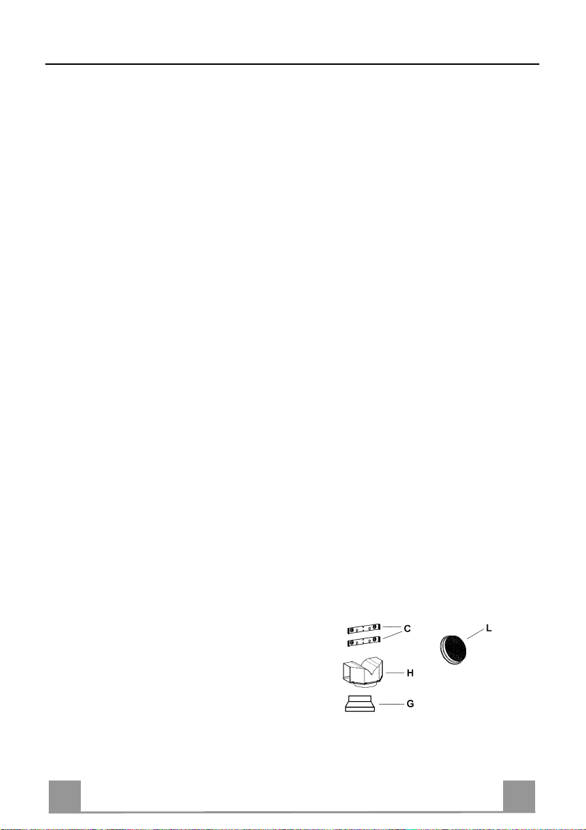
1. Illuminazione
E' costituita da due lampade da 40 W. Per effettuare una sostituzione operare come segue
(fig.10):
Togliere uno dei perni ai lati della plafoniera. Far scorrere il vetro verso il lato senza perno
fino a liberare la punta opposta, quindi tirare leggermente verso il basso.Sostituire le lam-
pade e rimontare il vetro con sequenza opposta.
2.Filtri
Ad intervalli più o meno frequenti, secondo l'uso della cappa, comunque una volta ogni 2
mesi, i filtri metallici debbono essere smontati e lavati con acqua calda saponosa, o diret-
tamente lavati in lavastoviglie e rimontati asciugati (i filtri in carbone attivo non devono
essere assolutamente lavati e devono essere sostituiti ogni 2 mesi).
3.Pulizia
Per la pulizia esterna della cappa utilizzare un panno umido con alcool o con prodotti adat-
ti reperibili in commercio. Evitate di usare degli elementi abrasivi.
IMPORTANTE: L'impiego di fiamma libera è dannoso ai filtri, pertanto è sconsigliato di
lasciare acceso un bruciatore a gas senza pentola. È obbligatorio mettere in atto le opera-
zioni di pulizia della cappa o dei filtri, non che la loro periodica sostituzione secondo le
nostre istruzioni per evitare pericoli di incendio.
ATTENZIONE: La casa produttrice non risponde degli eventuali danni causati dalla
mancata manutenzione del filtro antigrasso (lavaggio ogni due mesi), sostituzione del filtro
carbone ed il non rispetto delle istruzioni di montaggio ed allacciamento elettrico sopra de-
scritte.

EN
1
0
10
WARNINGS - COMPONENTS
WARNINGS
This appliance has been designed for use as either an EXTRACTION (ducting to the outside)
or RECIRCULATION (filtering) hood. The measurements contained on the drawings in this
booklet refer to two models of cooker hood. Therefore, it is essential that you refer to the cor-
rect drawing when taking measurements for installation.
- The minimum distance between the cooking surface and the metal grease filters on the
underside of the hood must be 650mm.
- This cooker hood must be installed in accordance with the installation instructions and
all requirements must be adhered to.
- If the room where the cooker hood is to be used contains a fuel burning appliance such
as a central heating boiler then its flue must be of the room sealed or balance flue type.
- If other types of flue or appliances are fitted ensure that there is an adequate supply of
air to the room.
- When the range hood and appliance supplied with energy other than electricity are
simultaneously in operation, the negative pressure in the room must not exceed 4 Pa
(4x10⁻⁵ bar).
- The ducting system for this appliance must not be connected to any ventilation system
which is being used for any other purpose.
- The ducting system for this appliance must not be connected to any existing ventilation
system which is being used for any other purpose.
- Do not leave naked flames or carry out flambè cooking under this cooker hood.
- This appliance is not intended for use by persons (including children) with reduced
physical, sensory or mental capabilities, or lack of experience and knowledge, unless
they have been given supervision or instruction concerning use of the appliance by a
person responsible for their safety.
- Children should be supervised to ensure that they do not play with the appliance
CONNECTING THE POWER CABLE TO THE MAINS POWER SUPPLY
Before installation, check that the mains voltage indicated on the rating plate inside the appli-
ance corresponds to the voltage available in your home. If the Hood is not fitted with a plug, fit
the power cable with a plug of a type approved for the load indicated on the rating plate; when
connecting directly to the mains, insert an omnipolar circuit breaker with a minimum contact
aperture of 3mm and a size suitable for the load in question between the appliance and the
mains supply, making sure it is of a type that complies with current regulations.
COMPONENTS
- 2 No Wall Brackets C
- 1 No 150-120mm Ducting Spigot G
- 1 No Air Outlet Connection H (Optional)
- 2 No Charcoal Filters L(Optional)

EN
1
1
11
INSTALLATION
The cooker hood must be installed centrally over a cooking appliance. The minimum distance
between the cooking surface and the metal grease filters on the underside of the hood must be
at least 650mm.
To install the hood proceed as follows:
1) Drill six 8mm diameter holes at X1-X2-J and insert the plastic rawl plugs supplied as illus-
trated in fig. 2 ensuring the brackets are fitted as shown in the blow up.
2) Secure the two brackets Cto the wall inserting two of the screws supplied through the two
holes on line X1-X2 as illustrated in fig. 2.
3) Slide the canopy down the wall to locate the key hole over the washer then secure the can-
opy to the wall by inserting two of the screws supplied through the two outer holes in the
rim of the canopy J1 and J2 as illustrated in fig. 3.
4) EXTRACTION OR RECIRCULATION INSTALLATION:
• EXTRACTION (DUCTED)
When installing the ducted version, connect the hood to the chimney using either a flexible or
rigid pipe ø 150 or 120 mm, the choice of which is left to the installer.
• To install a ø 120 mm air exhaust connection, insert the reducer flange 9on the hood body
outlet.
• Fix the pipe in position using sufficient pipe clamps (not supplied).
• Remove any activated charcoal filters.
• RECIRCULATION (FILTERED)
• When the hood is fitted in the recirculation mode the Air Outlet Connection Hshould be
fitted as illustrated in fig. 6.
• Fit the (optional) charcoal filters by repeating the following operation on each side of the
motor housing. Place the two key hole slots in the filter Land turn the filter clockwise to
lock the filter in position as illustrated in fig. 7.
WARNING: It is a possible fire hazard if the metal grease filters are not cleaned and the
charcoal filters replaced regularly.
Fitting The Chimney
5) FITTING THE CHIMNEY UPPER
To fit the upper chimney A, place the top edge of the chimney over the bracket Cas illus-
trated in fig. 8 and secure the chimney using two of the 2.9mm self tapping screws pro-
vided.
The distance Hin the height between the fixing holes X1 and X2 is determined by the
height of the upper chimney A.
6) FITTING THE CHIMNEY LOWER
To fit the lower chimney B, apply slight force to the two rear edges to increase the width
of the apperture, then sleeve the chimney Bover the chimney Aas illustrated in fig. 9.

EN
1
2
12
USE - MAINTENANCE
USE
The cooker hood functions are controlled by a series of slider or push button switches mounted
on the front of the hood and control the worktop lighting and fan motor speeds. This cooker
hood will not remove steam.
1)SLIDER SWITCHES
- A switch controls the wotktop lighting - ON/OFF.
- A switch controls the fan speeds - OFF/ON-1-2-3.
- The red neon lamp illuminates when the motor is switched ON .
2)PUSH BUTTON SWITCHES
- A switch controls the worktop lighting - ON/OFF.
- A button switches the motor OFF/ON at the low speed setting.
- A button switches the motor to the medium speed setting.
- A button switches the motor to the high speed setting.
- The red neon lamp illuminates when the motor is switched ON.
3)SPEED SETTINGS
- 1/Low should be selected when simmering or when using only one pan.
- 2/Medium should be selected for cooking when using up to four pans.
- 3/High should be selected when frying or cooking food with a strong odour.
MAINTENANCE
N.B. Before carring out any kind of maintenance, cleaning or replacing lamps, disconnect the
hood from the mains supply.
1. Lighting
Comprises two 40W bulbs. To replace the bulbs, proceed as follows (fig.10): Remove one
of the pins at the sides of the lamp cover. Slide the glass towards the side from which the
pin has been removed until the opposite edge has been freed, then pull gently downwards.
Replace the bults and fit the glass again by repeating the above operations in reverse order.
2. Filters
- The metal grease filter should be cleaned every two months or more frequently if the hood
is used consistently and can be cleaned in a dishwasher or by hand using a mild detergent
or liquid soap. When replacing, ensure that they are dry.
- The charcoal filter cannot be washed and should be replaced at least every 2 months or
more frequently if the hood is used consistently.
3. Cleaning
When cleaning the hood, it is recommended to use a damp cloth and mild liquid household
cleaner. Never use abrasive cleaning materials.
IMPORTANT: When using a gas hob in connection with the cooker hood never leave the
burners of the hob uncovered while the hood is in use or when the pans have been re-
moved. It is very important to follow all instructions for cleaning the hood and filters.
There could be a possible fire hazard if the filters are not replaced according to these in-
structions.
ATTENTION: The manufacturer declines all responsibility for any damage or injury
caused as a result of not following the instructions for installation, for maintenance and re-
placement times of filters indicated (in order to avoid a possible risk of fire when the filters
are saturated with grease).

FR
1
3
13
ATTENTION - COMPOSANTS
ATTENTION
Cet appareil a été conçu pour être employé en version ASPIRANTE (évacuation de l'air vers
l'extérieur) ou en version RECYCLAGE (air conduite vers l'intérieur).
- La distance minimum entre le plan de cuisson et la partie inférieure de la hotte doit
être au moins de 650mm.
- Il faut prévoir une aération convenable de la pièce lorsque la hotte et les appareils ali-
mentés avec énergie différente de celle éléctrique sont utilisés en même temps; la pres-
sion négative de la pièce ne doit pas dépasser 4Pa (4x10⁻⁵ bar).
- L'air recueillie ne doit pas être dirigée dans un conduit utilisé pour la décharge des
fumées des appareils alimentés avec énergie différente de celle éléctrique.
- Respecter les prescriptions des autorités compétentes relatives à la décharge de l'air à
evacuer.
- Eviter la présence de flammes libres dans l'espace au dessous de la hotte.
- La hotte a été construite avec isolement en classe II, donc il n'y a pas besoin de la relier
à la terre.
- Avant d'effectuer toutes les opérations d'entretien, débrancher l'appareil de l'alimen-
tation éléctrique.
- Cet appareil ne doit pas être utilisé par des personnes (y compris les enfants) ayant des
capacités psychiques, sensorielles ou mentales réduites, ni par des personnes n’ayant
pas l’expérience et la connaissance de ce type d’appareils, à moins d'être sous le
contrôle et la formation de personnes responsables de leur sécurité.
- Les enfants doivent être surveillés pour s'assurer qu'ils ne jouent pas avec l'appareil.
BRANCHEMENT DU CÂBLE ÉLECTRIQUE AU RÉSEAU
Avant l’installation, vérifier que la tension du réseau indiquée sur la plaquette se trouvant à
l’intérieur de l’appareil correspond à la tension électrique de votre habitation. Si la hotte n’est
pas munie de fiche électrique, monter une fiche à norme sur le câble d’alimentation qui soit
adaptée à la tension indiquée sur la plaquette des caractéristiques. En cas de branchement élec-
trique direct sur le réseau, il faudra placer un interrupteur omnipolaire entre l’appareil et le ré-
seau ayant une ouverture minimum entre les contacts de 3 mm, et adapté à la tension et répon-
dant aux normes en vigueur.
COMPOSANTS
- 2 brides C
- 1 bride de réduction G
- 1 raccord filtrant H (optionnel)
- 2 filtres charbon actif L (optionnel)

FR
1
4
14
INSTALLATION
La hotte doit être assemblée au centre du plan de cuisson. La distance minimum entre le plan
de cuisson et la surface inférieure de la hotte doit être de 650mm.
Pour l'assemblage de la hotte procéder de la manière suivante:
1)Faire n°6 trous (X1-X2-J) de 8mm respectant les chiffres indiqués à la fig. 1.
2) Pour les différents assemblages utiliser les vis et les vis tamponnées fournies..
3) Bloquer l'étrier C (fig. 2) à la paroi dans les trous X1-X2.
4) Fixer la hotte à la paroi dans les trous J1 et J2 (fig. 3) .
5) Assemblage ASPIRANTE ou FILTRANT.
• ASPIRANTE
En cas d’installation en version aspirante, brancher la hotte à la tuyauterie de sortie via un tube
rigide ou flexible de ø 150 ou 120 mm, au choix de l’installateur.
• En cas de branchement avec un tube de ø120 mm, insérer le flasque de réduction 9sur la
sortie du corps de la hotte.
• Fixer le tube par des colliers appropriés. Le matériau nécessaire n’est pas fourni.
• Retirer les éventuels filtres anti-odeur au charbon actif.
• FILTRANT (OPTION)
- Insérer le Raccord Sortie Air H(fig. 6).
- Assembler les filtres charbon actif L(fig. 7) en les centrant dans le support moteur M et
les bloquer en tournant dans sens horaire (environ 10°) jusqu'à l'arret. Pour les opérations
de démontage faire les opérations inverses.
6) Fixer la cheminée supérieure A(fig. 8) à l'étrier C(fig. 2/fig. 8) utilisant 4 vis autotarau-
deuses de Ø 2,9mm en dotation. La distance entre les alésages de fixation X1 et X2 est dé-
terminée par la hauteur de la cheminée supérieure H.
7) Appliquer frontalement la cheminée inférieure B(fig. 9) en élargissant légèrement les deux
parties latérales et l'insérer ensuite dans la hotte (fig. 9).

FR
1
5
15
UTILISATION - ENTRETIEN
UTILISATION
Nous vous recommandons de faire fonctionner l'appareil quelque temps avant de procéder à la
cuisson de n'importe quel aliment, de le laisser fonctionner encore pendant 15 minutes après la
cuisson et de toute manière tant que les odeurs n'auront pas disparu.
1) Bandeau de commandes avec interrupteurs
- Un interrupteur qui commande l'allumage de l'installation d'éclairage.
- Un interrupteur pour commuter les trois vitesses d'exercice.
- Un voyant général de signalisation moteur en service.
2) Bandeau de commandes avec touches
- Une touche qui commande l'allumage du moteur en première vitesse, indiquée pour une
circulation d'air continue particulièrement silencieuse, en présence de faibles vapeurs de
cuisson.
- Une touche qui commande le moteur en deuxième vitesse, indiquée dans la plupart des
conditions d'emploi vu l'excellent rapport entre le débit d'air traité et le niveau de bruit.
- Une touche qui commande le moteur en troisième vitesse, indiquée en cas d'importantes
émissions de vapeurs de cuisson, également pendant des périodes prolongées.
- Une touche qui commande l'allumage de l'installation d'éclairage.
ENTRETIEN
N.B. Pour n'importe quelle opération d'entretien et de réparation débranchez l'appareil.
1. Eclairage
Il est constitué par deux lampes de 40W. Pour effectuer un remplacement, suivre les ins-
tructions suivantes (fig.10): Retirer l'un des goujons qui se trouvent sur les côtés du pla-
fonnier. Faire coulisser le verre sur le côté sans le goujon, jusqu'à dégager la pointe oppo-
sée, puis tirer légèrement vers le bas. Remplacer les lampes et remonter le verre en effec-
tuant les opérations décrites ci-dessus à rebours.
2. Filtres
A des intervalles plus ou moins fréquents en fonction de leur utilisation, mais en tout cas
une fois tous les 2 mois, les filtres métalliques doivent être lavés dans le lave-vaisselle ou à
la main dans de l'eau tiède savonneuse (les filtres au charbon actif ne doivent jamais etre
lavés et doivent être remplacés tous les 2 mois).
3.Nettoyage
Pour ce qui concerne le nettoyage externe de la hotte, utiliser un chiffon humide et de l'al-
cool ou d'autres produits appropriés. N'employez pas de produits abrasifs.
IMPORTANT: Il est obligatoire d'effectuer les opérations de nettoyage de la hotte et des fil-
tres, ainsi que de les remplacer périodiquement selon nos instructions pour éviter les risques
d'incendie.
ATTENTION: Le fabricant décline toute résponsabilité pour les dommages provoqués par le
non entretien des filtres anti-graisse (nettoyage tous les 2 mois) ainsi que par le non replace-
ment périodiques des filtres à charbon et par le non respect des instructions de montage et de
branchement.

DE
1
6
16
HINWEIS - KOMPONENTEN
HINWEISE
Dieses Gerät ist sowohl als ABLUFTHAUBE (Abführung der Luft nach außen), als auch als
UMLUFTHAUBE (Filtrierung der Dünste im Innern) verwendbar.
- Der Mindestabstand zwischen Kochfeld und Unterseite der Haubesoll 650 mm betragen.
- Wenn die Luft nach Außen abgeführt wird (Abluftbetrieb), muss die Haube nach den folgenden An-
weisungen installiert werden.
- Bei gleichzeitigem Betrieb der Dunstabzugshaube im Abluftbetrieb und Feuerstätten darf im Auf-
stellraum der Feuerstätte der Unterdruck nicht größer als 4 Pa (4x10⁻⁵ bar) sein.
- Das Abluftrohr der Haube darf keinesfalls an den Rauchabzug von Feuerstätten angeschlossen wer-
den.
- Die Abluftvorschriften der zuständigen Behörden beachten.
- Niemals eine Flamme unter der Dunsthaube unbedeckt lassen.
- Das Gerät entsprichtder SchutzklasseII und muss daher nichtgeerdetwerden.
- Vor Wartungsarbeiten muss das Gerät spannungslos gemacht werden.
- Dieses Gerät darf nicht von Personen, auch Kindern, mit verminderten psychischen, sensorischen
und geistigern Fähigkeiten, oder von Personen ohne Erfahrung und Kenntnisse benutzt werden, so-
fern sie nicht von für ihre Sicherheit verantwortlichen Personen beaufsichtigt und beim Gebrauch
des Geräts angeleitet werden.
- Kinder dürfen sich nicht unbeaufsichtigt in der Nähe des Geräts aufhalten und auf keinen Fall mit
dem Gerät spielen.
ANSCHLUSS DES STROMKABELS AN DAS NETZ
Vor der Installation muss kontrolliert werden, ob die am Typenschild im Geräteinnern angege-
bene Netzspannung der Spannung Ihres Haushalts entspricht. Falls das Gerät ohne Stecker ist,
muss das Kabel mit einem genormten, für die am Typenschild angegebene Last ausreichenden
Stecker versehen werden; bei direktem Anschluss an das Netz muss ein korrekt dimensionier-
ter allpoliger Schalter mit einer Mindestkontaktöffnung von 3 mm zwischengeschaltet werden,
der den einschlägigen Vorschriften entspricht.
KOMPONENTEN
- 2 Wandhalterungen C
- 1 Reduzierflansch G
- 1 Filterstutzen H(Option)
- 2 Aktivkohlefilter L (Option)

DE
1
7
17
MONTAGE
Die Haube muss mittig über dem Kochfeld installiert werden. Der Mindestabstand zwischen
Kochfeld und Unterseite der Haube soll 650 mm betragen.
Für die Installation wie folgt vorgehen:
1) 6 Löcher (X1-X2-J) mit 8 mm Durchmesser nach den Maßangaben der Abb.1 ausführen.
2) Die für die jeweilige Montage mitgelieferten Schrauben und Dübel verwenden.
3) Die Wandhalterungen C (Abb. 2) mittels der Bohrungen X1-X2 an der Wand befestigen.
4) Die Haube mittels der externen Bohrlöcher J1 und J2 (Abb. 3) an der Wand befestigen.
5) Montage als ABLUFTHAUBE oder UMLUFTHAUBE:
ABLUFTBETRIEB
Bei Abluftbetrieb kann die Haube vom Installateur wahlweise mittels Rohr oder Schlauch (ø
150 oder 120 mm) an den Auslass angeschlossen werden.
- Bei Verwendung eines Anschlussrohres ø 120 den Reduzierflansch 9am Haubenausgang
anbringen.
- Das Rohr mit passenden Rohrschellen fixieren. Das hierzu erforderliche Material wird
nicht mitgeliefert.
- Eventuell vorhandene Aktivkohlefilter ausbauen.
UMLUFTBETRIEB (OPTION)
- Den Filterstutzen Heinbauen (Abb. 6).
- Den Aktivkohlefilter L (Abb.7) einlegen und durch Drehen im Uhrzeigersinn (um zirka
10°) einrasten lassen. Zum Ausbauen in umgekehrter Reihenfolge vorgehen.
Montage der Kamine:
6) Befestigen Sie das obere Kaminteil A (Abb. 8) mit den vier beiliegenden, selbstschneiden-
den Schrauben Ø 2,9 mm an den Halterungen C(Abb.2/Abb.8). Der Abstand zwischen
den Bohrlöchern X1 und X2 hängt von der Höhe des oberen Kaminteils Hab.
7) Um das untere Kaminteil B (Abb. 9) anzubringen die beiden Seitenteile leicht auseinan-
derbiegen und dann an der Haube einsetzen (Abb. 9).

DE
1
8
18
BEDIENUNG - WARTUNG
BEDIENUNG
Die Dunsthaube ist, je nach Modellart, mit verschiedenen Schiebeschaltern oder Drucktasten
an der Haubenfront ausgestattet, mit denen die Arbeitsflächenbeleuchtung und die Motorge-
schwindigkeit geschaltet werden .
1) Schiebeschaltung
Ein Schalter schaltet die Beleuchtung ein.
Ein Schalter steuert die drei Gebläsestufen.
Eine Kontrolllampe zeigt den Motorbetrieb an.
2) Drucktastenschaltung
Ein Schalter schaltet die Beleuchtung ein
Ein Schalter schaltet den Motor ein und aus ( niedrigste Stufe).
Ein Schalter schaltet die mittlere Stufe ein.
Ein Schalter schaltet die höchste Stufe ein.
Die rote Kontrolllampe zeigt an, wenn der Motor eingeschaltet ist.
3) Geschwindigkeitsstufen
1 / niedrig bei Benutzung einer Kochplatte
2 / mittel beim Gebrauch bis zu vier Kochplatten
3 / hoch beim Braten oder bei starkem Kochdunst
WARTUNG
N.B. Vor sämtlichen Wartungs- und Reparaturarbeiten bzw. vor Auswechseln der Lampen
muss die Stromzufuhr zum Gerät unterbrochen werden.
1. Beleuchtung
Die Beleuchtung besteht aus zwei Lampen zu 40W. Beim Austausch einer Lampe ist wie
folgt vorzugehen (Abb.10): einen der Stifte an der Lampenabdeckungsseite entfernen.
Dann das Glas auf die Seite ohne Stift schieben, bis das gegenüberliegende Ende frei liegt
und etwas senken. Die Lampen austauschen und die Glasabdeckung in umgekehrter Rei-
henfolge wieder montieren.
2. Filter
Je nach Einsatzhäufigkeit müssen die Metallfettfilter in angebrachten Zeitabständen (ma-
ximal alle 2 Monate) demontiert und mit warmem Seifenwasser bzw. im Geschirrspüler
gereinigt und trocken wieder montiert werden (Aktivkohlefilter dürfen keinesfalls gewa-
schen werden, sondern sind alle 2 Monate auszuwechseln).
3.Pflege
Zur Außenreinigung der Haube ein mit Alkohol oder zweckentsprechenden, handelsübli-
chen Reinigungsmitteln angefeuchtetes Tuch verwenden. Scheuermittel sind zu vermei-
den.
WICHTIG: Offene Flammen schädigen die Filter; deshalb wird davon abgeraten, Gaskoch-
stellen ohne Kochtopf brennen zu lassen. Die Maßnahmen zur Reinigung der Haube bzw. der
Filter und das Auswechseln der Filter haben verbindlich gemäß unseren Vorschriften und in
regelmäßigen Zeitabständen zu erfolgen, um Brandgefahr zu vermeiden.
ACHTUNG: Die Herstellerfirma übernimmt keine Haftung für Schäden, die durch unterlas-
sene Wartung des Fettfilters (alle zwei Monate auswaschen), unterlassenes Auswechseln des
Aktivkohlefilters und Nichtbeachtung der obengenannten Anleitungen zur Montage und zum
Elektronanschluss entstehen.

TR
1
9
19
UYARILAR - PARÇALARI
UYARILAR
Bu cihaz ASPİRATÖRLÜ (havayı dışarı tahliye eden) yada FİLTRELİ(içerideki havayı
tekrar aktive eden) model davlumbaz olarak tasarlanmıştır.
- Tezgâh (setüstü ocak) ile davlumbazın alt kısmı arasındaki mesafe en az 650 mm olma-
lıdır.
- Davlumbazda havanın dışarı tahliye edildiği (aspiratörlü kullanım şekli) söz konusu
olduğunda aşağıdaki talimatlara uyunuz.
- Davlumbaz ile elektrik enerjisinden farklı bir enerji ile çalışan cihazların aynı anda
çalışır durumda oldukları mekânda iyi bir havalandırma bulunmasına dikkat ediniz;
odanın negatif basıncı (vakumu) 4 atmosfer basıncını aşmamalıdır (4x10⁻⁵ bar).
- Mekânda toplanan hava, elektrik dışında bir enerji ile çalışan cihazlardan çıkan du-
manları tahliye eden kanala-bacaya sevk edilmemelidir.
- Hava tahliyesi ile ilgili olarak yerel yetki mercilerinin yönetmeliklerine uyunuz.
- Davlumbazın altındaki alanda serbest alev bulunmasına engel olunuz.
- Davlumbaz Sınıf’II ye dahil izolasyona sahip olarak imal edilmiştir ve bu nedenle top-
rak bağlantısı gerektirmez.
- Tüm bakım işlemlerinden önce cihazın elektrik bağlantısını kesiniz.
- Bu alet, güvenliklerinden sorumlu kişiler tarafından kontrol edilmedikleri veya eğitil-
medikleri sürece; fiziksel, duyumsal ve zihinsel kapasitesinde kısıtlama olan (çocuklar
dahil) veya aleti kullanma tecrübesi ve bilgisi olmayan kişiler tarafından kullanılamaz.
- Bebeklerin, aletle oynamadıklarından emin olmak için kontrol edilmeli gerekir.
BESLEME KABLOSUNUN ŞEBEKEYE BAĞLANMASI
Yerleştirmeden önce, şebeke geriliminin cihazın içindeki etikette belirtilen gerilime uygun ol-
duğunu kontrol ediniz. Davlumbazın bir kablosu olmaması durumunda, besleme kablosuna,
özellikler etiketinde belirtilen yüke uyarlanmışbir fişmonte ediniz; şebekeye doğrudan elekt-
rik bağlantısı yapılması halinde, cihaz ile şebeke arasına, temaslar arasında minimum 3 mm'lik
bir aralığı bulunan, yüke göre boyutlandırılmışve yürürlükteki norma uygun çok kutuplu bir
şalter yerleştiriniz
PARÇALARI
- 2 adet tesbit braketi C
- 1 adet redüksiyon flanşı G
- 1 adet filtre rakoru H (isteğe bağlı)
- 2 adet aktif karbon filtresi L(isteğe bağlı)

TR
2
0
20
MONTAJ
Davlumbaz setüstü ocağın tam merkezine monte edilmelidir. Setüstü ocak ile davlumbazın altı
arasındaki mesafe en az 650 mm olmalıdır.
Davlumbazın montajı için şu şekilde hareket ediniz:
1)Şekil 1’deki ölçülere uyarak 6 adet 8 mm çapında delik açınız (X1-X2-J).
2)Muhtelif parçaların montajlarında cihaz donanımındaki vidaları ve dübelleri kullanınız.
3)Braketleri C(şekil 2) duvardaki deliklere X1-X2 tesbit ediniz.
4)Davlumbazı duvardaki dışdeliklere J1 ve J2 tesbit ediniz (şekil 3).
5)ASPİRATÖRLÜ yada FİLTRELİmodelin montajı:
• ASPIRATÖRLÜ
Aspiratörlü model montajında Davlumbazı çıkışborusuna seçimi montöre kalmışsert ya da
esnek 150 veya 120 mm çapında bir boru ile bağlayınız.
• 120 mm çapında boru ile bağlamak istiyorsanız Redüksiyon Flanşını 9Davlumbaz Gövde-
si Çıkışına takınız.
• Boruyu uygun kelepçelerle tesbit ediniz. Bu malzeme donanımda verilmemiştir.
• Varsa Aktif Karbonlu Koku Filtrelerini çıkarınız.
• FİLTRELİ(OPSİYONEL MODEL)
- Filtre rakorunu Htakınız (şekil 6).
- Aktif karbonlu filtreleri L(şekil 7) saat yönünde (yaklaşık 10° derece) döndürüp klik sesi
duyunca takıldıklarını anlayınız. Sökerken bu işlemleri tersine yapınız.
Baca Montajı
6) Üst bacayı A(şekil 8) braketlere C(şekil 2 / şekil 8) donanımdaki 4 adet 2,9 mm.lik vidayı
kullanarak sabitleyiniz. Tesbit vidaları arasındaki X1 - X2 mesafesi üst bacanın boyuna H
göre belirlenir.
7) Ön cepheden, yan taraflarını hafifçe açıp davlumbaza geçirmek suretiyle alt bacayı B(şe-
kil 9) monte ediniz (şekil 9).
This manual suits for next models
1
Table of contents
Languages:
Other Dominox Ventilation Hood manuals
Popular Ventilation Hood manuals by other brands

Mora
Mora E023DII1K28NG2BSB Instruction on mounting and use

XtremeAIR
XtremeAIR PRO-X PX01-I36 Installation guide & user manual

Atag
Atag WS6111MR Instructions for use

Orbegozo
Orbegozo TL 06260 A IN instruction manual

Jenn-Air
Jenn-Air 30" Installation Instructions and Use & Care Guide

CPS
CPS ABM-HOOD owner's manual