APsmart RSD-S-PLC Instruction Manual

smart
Installation / User Manual
TRANSMITTER-PLC/TRANSMITTER-PLC-PCBA/
TRANSMITTER-PLC-OUTDOOR KIT
ALTENERGY POWER SYSTEM Inc. www.APsystems.com
© All Rights Reserved
APsmart rapid shutdown system
RSD-S-PLC
Rev1.0 2019/09/11

TABLE OF CONTENTS
IMPORTANT SAFETY INSTRUCTIONS---------------------------------------------------------1
Safety Instructions -----------------------------------------------------------------------------1
Symbols replace words on the equipment, on a display, or in manuals-----------------1
RSD PRODUCTS----------------------------------------------------------------------------------2
TRANSMITTER PRODUCTS---------------------------------------------------------------------3
SYSTEM WIRING DIAGRAM--------------------------------------------------------------------4
RSD-S-PLC INSTALLATION---------------------------------------------------------------------6
Step 1: Install the RSD-S-PLC ----------------------------------------------------------------7
Step 2: According to the component arrangement, connect the output port of the
RSD-S-PLC and connect the input port to the junction box--------------------8
Step 3: Connect the RSD-S-PLC serially connected output to the inverter with a
self-made DC extension cable------------------------------------------------------8
TRANSMITTER-PLC INSTALLATION ----------------------------------------------------------9
TECHNICAL DATA—RSD-S-PLC---------------------------------------------------------------12
TECHNICAL DATA—TRANSMITTER-PLC-----------------------------------------------------13
TECHNICAL DATA—TRANSMITTER-PLC-OUTDOOR KIT----------------------------------14
TECHNICAL DATA—TRANSMITTER-PLC-PCBA---------------------------------------------15
ORDERING INFORMATION --------------------------------------------------------------------16

IMPORTANT SAFETY INSTRUCTIONS
This manual contains important instructions to be followed during installation and maintenance of the
APsmart RSD and Transmitter. To reduce the risk of electrical shock and ensure the safe installation
and operation of the APsmart RSD and Transmitter, the following symbols appear throughout this
document to indicate dangerous conditions and important safety instructions.
Safety Instructions
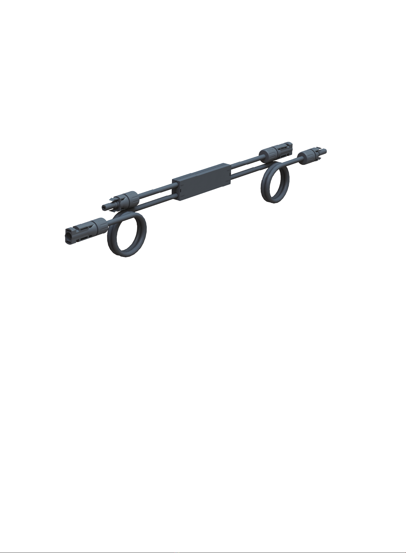
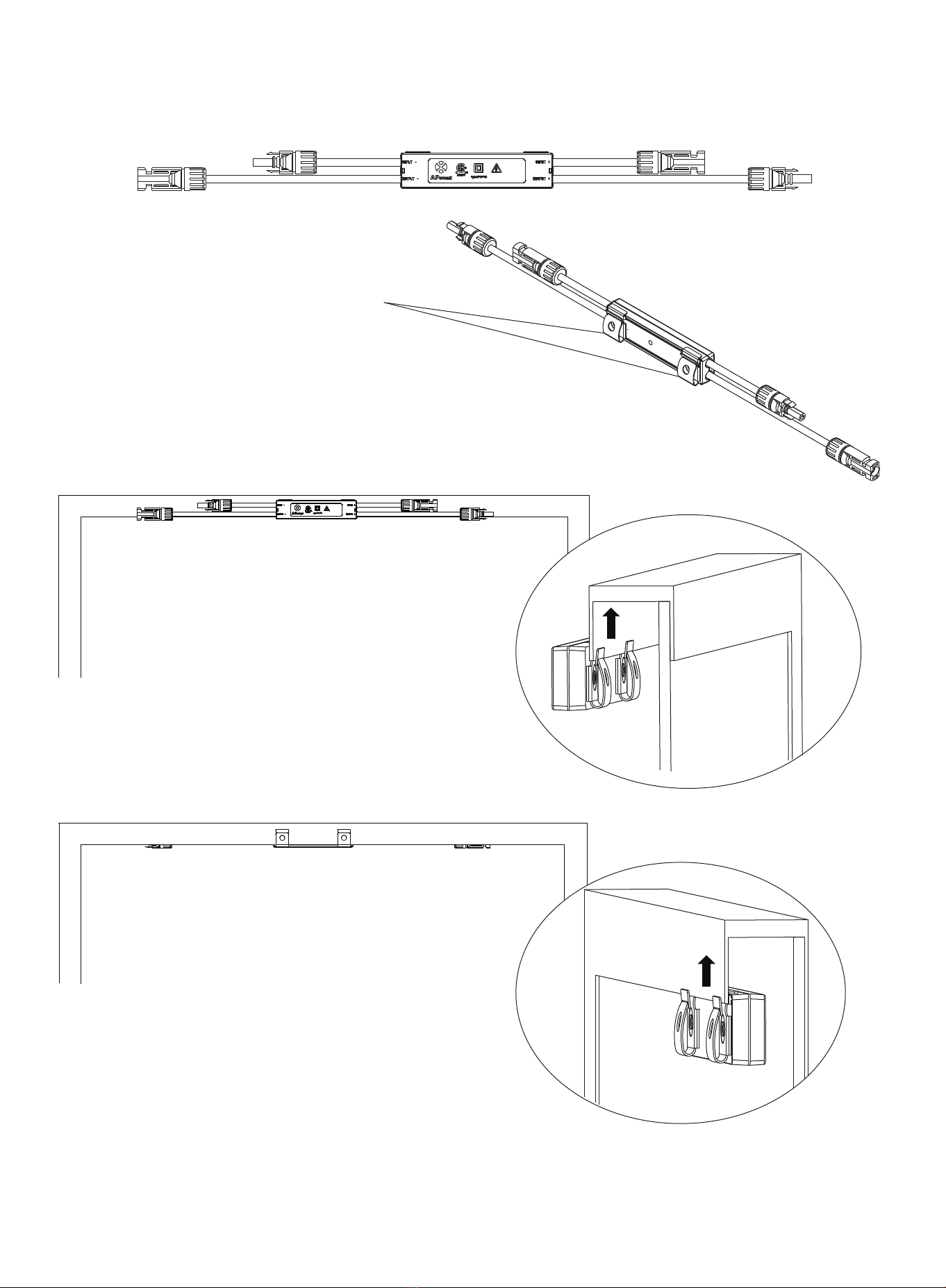
· Do NOT disconnect the PV module from the RSD-S-PLC without first disconnecting the AC power.
· Only qualified professionals should install and/or replace the APsystems RSD-S-PLC.
· Perform all electrical installations in accordance with local codes.
· Before installing or using the RSD-S-PLC, please read all instructions and cautionary markings in
the technical documents and on the APsystems microinverter system and the solar array.
· Be aware that the body of the running RSD-S-PLC is the heat sink and can reach high
temperatures. To reduce risk of burns, do not touch the body of the RSD-S-PLC.
· Do NOT attempt to repair the RSD-S-PLC. If it fails, contact APsystems Customer Support to
obtain an RMA number and start the replacement process. Damaging or opening the RSD-S-PLC
will void the warranty.
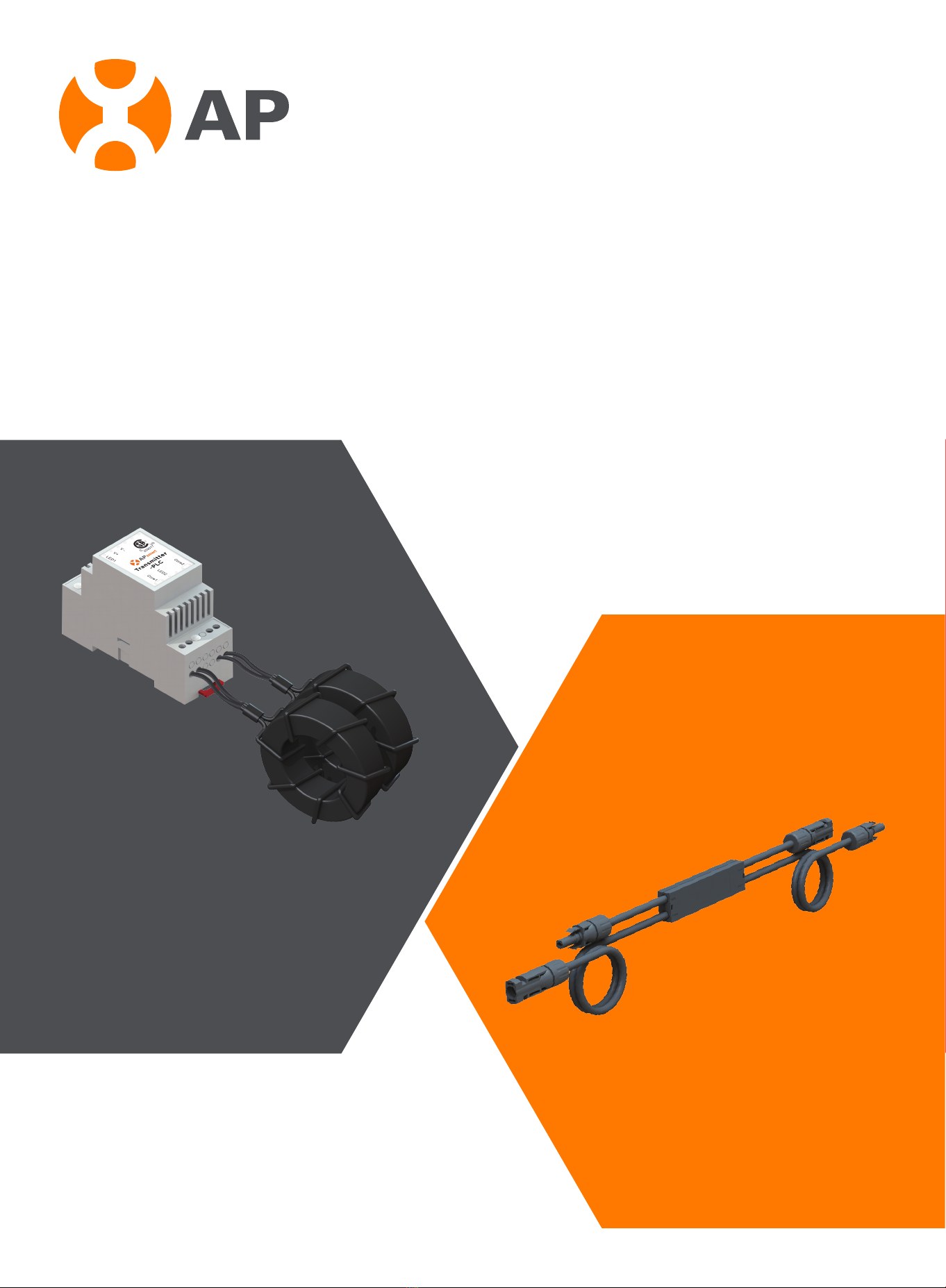
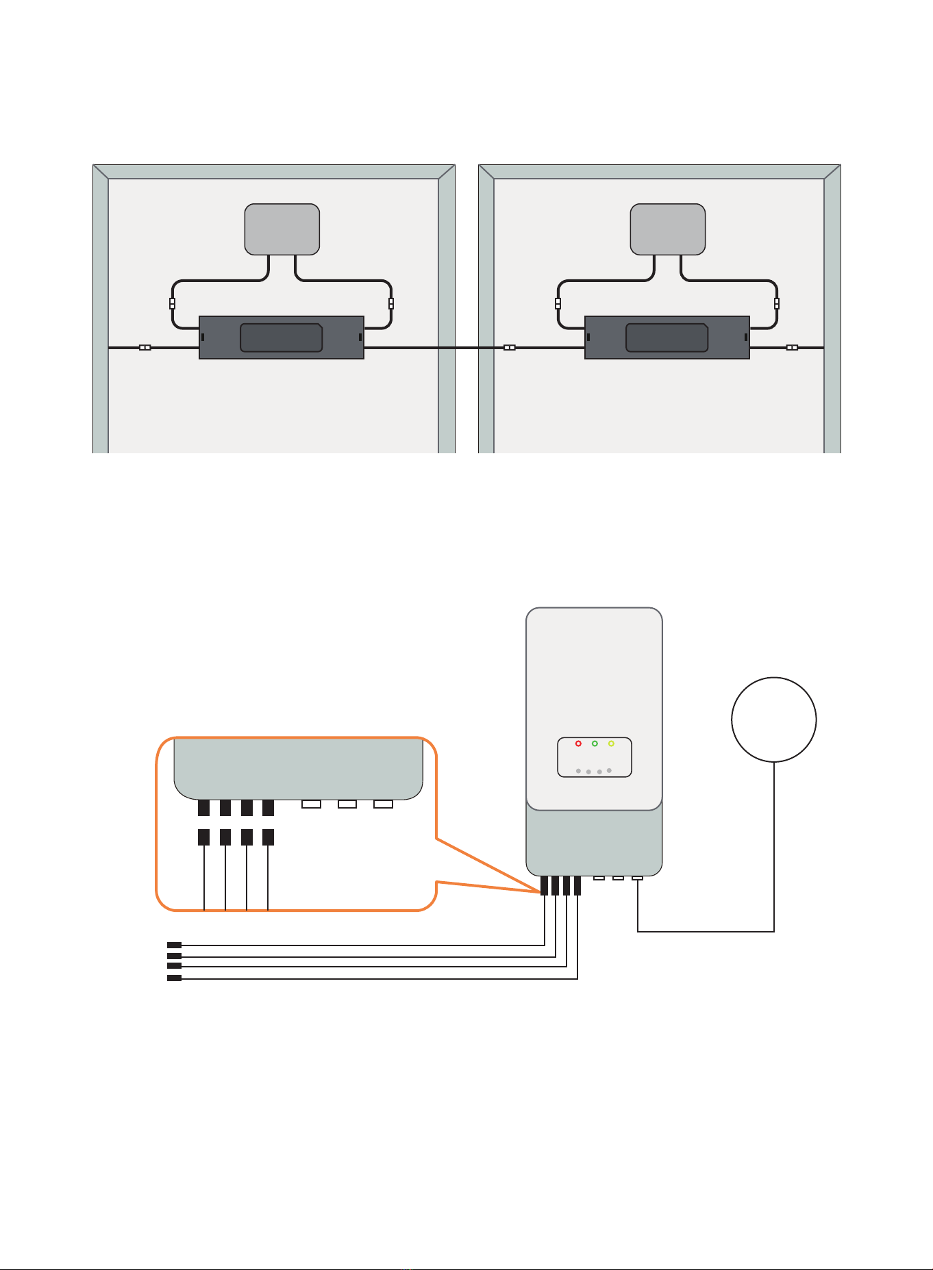
The transmitter control power supply MUST be on the same AC branch circuit
as the inverter to meet rapid shutdown requirements.
Symbols replace words on the equipment, on a display, or in
manuals
Qualified personne:
Person adequately advised or supervised by an electrically skilled person to enable him or her to
perceive risks and to avoid hazards which electricity can create. For the purpose of the safety
information of this manual, a "qualified person" is someone who is familiar with requirements
for safety, refrigeration system and EMC and is authorized to energize, ground, and tag
equipment, systems, and circuits in accordance with established safety procedures. The inverter
and endues system may only be commissioned and operated by qualified personnel.
1

RSD PRODUCTS
RSD-S-PLC:
· Meets NEC 2017 (690.12) requirements
· Switch o RSS Transmitter,
rapid shutdown the output of PV modules
· Meets SunSpec requirements
RSD-S-PLC meets SunSpec demands: to maintain proper functioning by continually receiving
heartbeat frame from Transmitter-PLC. In the meanwhile, users could stop the Transmitter-PLC by
AC switching out in case of emerency to realize the module-level rapid shutdown.
2

TRANSMITTER PRODUCTS
Transmitter-PLC:
Transmitter-PLC-Outdoor Kit:
Transmitter-PLC-PCBA:
· Meets NEC 2017 (690.12) requirements
· Switch o RSS Transmitter, rapid shutdown
the output of PV modules
·Meets SunSpec requirements
·Equipped with single/dual core
·Optional 120/240VAC power supply
·Optional 480/277VAC power supply
· Meets NEC 2017 (690.12) requirements
· Switch o RSS Transmitter, rapid shutdown
the output of PV modules
·Meets SunSpec requirements
·Equipped with single/dual core
·Optional 120/240VAC power supply
·Optional 480/277VAC power supply
· Meets NEC 2017 (690.12) requirements
· Switch o RSS Transmitter, rapid shutdown
the output of PV modules
·Meets SunSpec requirements
·Equipped with single/dual core
·Optional 120/240VAC power supply
·Optional 480/277VAC power supply
3

SYSTEM WIRING DIAGRAM
①RSD-S-PLC
②Transmitter-PLC
③Inverter
The APsmart Rapid Shutdown System (RSS) Transmitter-PLC is part of a rapid shutdown solution
when paired with APsystems RSD-S-PLC, a PV module rapid shutdown unit. While powered on, the
RSS Transmitter sends a signal to the RSD-S-PLC units to keep their PV modules connected and
supplying energy.
RSD-S-PLC units automatically enter rapid shutdown mode when the RSS Transmitter-PLC is
switched o and resume energy production when power is restored to the RSS Transmitter. This
solution complies with NEC 690.12 specifications for 2017 and supports the SunSpec signaling for
rapid shutdown.
4

①RSD-S-PLC
②Transmitter-PLC-Outdoor Kit
③Inverter
①RSD-S-PLC
②Inverter with Transmitter-PLC-PCBA
5

RSD-S-PLC INSTALLATION
INSTALLATION NOTES
Installation MUST comply with local regulations and technical rules:
①Perform all electrical installations in accordance with local codes.
②Be aware that only qualified professionals should install and/or replace the RSD-S-PLC.
③Before installing or using an RSD-S-PLC, please read all instructions and warnings in the technical
documents and on the inverter system itself as well as on the PV array.
④Be aware that installation of this equipment includes the risk of electric shock.
⑤Do not touch any live parts in the system, including the PV array, when the system has been
connected to the electrical grid.
⑥Ensure the solar module and inverter has been disconnected before installing an RSD-S-PLC.
Additional installation components from APsystems
Required parts and tools to complete the installation
· DC extension cable (sold separately)
In addition to your PV array and its associated hardware, you will need the following items:
· Rapid shutdown device installation kit (screw, nut)
· A torque wrench and a Phillips screwdriver
①Be sure to verify the voltage and current specifications of your PV module match with those of
the RSD-S-PLC.
②You must match the DC operating voltage range of the PV module with the allowable inpust
voltage range of the RSD-S-PLC.
③The maximum open circuit voltage of the PV module must not exceed the specified maximum
input voltage of the APsystem RSD-S-PLC.
6

Step 1: Install the RSD-S-PLC.
7
Buckle RSD-S-PLC on the PV module frame.
DC input - DC input +
DC output - DC output +
Mounting brackets
A. Front buckle
B. Back buckle
Note: Both installations can be installed anywhere on the PV module frame.

Step 2: According to the component arrangement, connect the
output port of the RSD-S-PLC and connect the input port to the
junction box.
Step 3: Connect the RSD-S-PLC serially connected output to the
inverter with a self-made DC extension cable.
8
self-made DC extension cable
GRID
DC 1
DC 2
DC 1 DC 2 DC Switch COM GRID
Input-
Output-
Input +
Output +
Input-
Output-
Input +
Output +

TRANSMITTER-PLC INSTALLATION
• Mount Transmitter-PLC and power supply on DIN rail
• Connect DC leads from power supply to transmitter-PLC
• Connect single/dual core(Core 1 and Core 2) to transmitter-PLC
Note: Install RSD-S-PLC before powering on Transmitter.
Place rapid shutdown system label no more than 1m (3ft) from Transmitteror AC
disconnect if not at same location.
Transmitter power supply must be on same AC branch circuit as inverter to meet
rapid shutdown requirements
9
V-V+
N L
V -
CUS
259077
smart
Power Supply
Transmitter-PLC
Core 1
Core 2
1
2
3
4
Optional power supply
120/240VAC
480/277VAC
1
3
4
LED1(Power)
V+
V -
Core 2
LED2(Signal)
Core 1
2

Note: Install RSD-S-PLC before powering on Transmitter.
• Pass either positive or negative homerun through Cores (Max 10 strings per core)
• Connect wires to AC side of Power supply
Max number of strings per Core: 10
Max string length: 30 modules
Max current per Core: 150A
Max cable length from inverter (+) to inverter (-): 1000ft (300m)
10
AC Wires for
Power Supply
Homerun
Only (+) or (-)
through Core
V-V+
N L
V -
CUS
259077
smart

Drilling Guide for .75" Conduit
61
6850
3×∅28
50
61
2×∅28
40
40
Drilling Guide for 1" Conduit
61
5254
3×∅35
54
61
2×∅35
52
52
11

TECHNICAL DATA—RSD-S-PLC
Model RSD-S-PLC
Input Data (DC)
Input operating Voltage Range 8-80V
Maximum Cont. Input Current (Imax) 15A
Maximum Input Power 800W
Output Data (DC)
Output operating Voltage Range 8-80V
Output Power Range 0-800W
Maximum System Voltage 1000V/1500V
Mechanical Data
Operating Ambient Temperature Range -40 °C to + 85 °C (-40 oF to +185 oF )
Dimensions (without cable&connectors) 5"x1.2"x0.6"(129mm x 30mm x 16mm)
Cable length Input 250mm/Output 1200mm or Customize
Module Connector MC-4 Compatible or Customize
Enclosure Rating Type 6P/IP68
Overtemperature protection Yes
Features & Compliance
Communication PLC
Safety Compliance NEC 2017 (690.12);UL1741;CSA C22.2 No. 330-17;
IEC/EN62109-1;2PFG2305
EMC Compliance FCC Part15;ICES-003;IEC/EN62109-1/-2/-3/-4
12

TECHNICAL DATA—TRANSMITTER-PLC
Model Transmitter-PLC
Main electrical data
Input Voltage 12 VDC
Input Current 1A
Communication PLC
Power Supply
Residential(optional)85-264VAC Input, 12VDC Output,
90mm x 17.5mmx58.4 mm
Commercial(optional)200-500VAC Input, 12VDC Output,
125.2mm x 40mmx113.5mm
Core data
Max.Current 300A(150AX2)
Max. System Voltage 1500VDC
Internal Opening For Wires 29mm
Max. Number Of Strings 10x2
Max. Supported PV Modules per String 30 modules
Environmental
Temperature -40℃~+85℃
Structure data
Dimensions (W x H x D) 90x35x62mm
Enclosure Environmental Rating IP30
Features & Compliance
Safety Compliance NEC 2017 (690.12);UL1741;CSA C22.2 No. 330-17
EMC Compliance FCC Part15;ICES-003
13

TECHNICAL DATA—
TRANSMITTER-PLC-OUTDOOR KIT
Model Transmitter-PLC-Outdoor Kit
Main electrical data
Input Voltage 12 VDC
Input Current 1A
Communication PLC
Power Supply
Residential(optional)85-264VAC Input, 12VDC Output,
90mm x 17.5mmx58.4 mm
Commercial(optional)200-500VAC Input, 12VDC Output,
125.2mm x 40mmx113.5mm
Core data
Max. Current 300A(150AX2)
Max. System Voltage 1500VDC
Internal Opening For Wires 29mm
Max. Number Of Strings 10x2
Max. Supported PV Modules per String 30 modules
Environmental
Temperature -40℃~+85℃
Structure data
Dimensions (W x H x D) 198.5x298x179mm
Enclosure Environmental Rating IP65
Features & Compliance
Safety Compliance NEC 2017 (690.12);UL1741;CSA C22.2 No. 330-17
EMC Compliance FCC Part15;ICES-003;IEC/EN62109-1/-2/-3/-4
14

TECHNICAL DATA—TRANSMITTER-PLC-PCBA
Model Transmitter-PLC-PCBA
Main electrical data
Input Voltage 12 VDC
Input Current 1A
Communication PLC
Power Supply
Residential(optional)85-264VAC Input, 12VDC Output,
90mm x 17.5mmx58.4 mm
Commercial(optional)200-500VAC Input, 12VDC Output,
125.2mm x 40mmx113.5mm
Core data
Max. Current 300A(150AX2)
Max. System Voltage 1500VDC
Internal Opening For Wires 29mm
Max. Number Of Strings 10x2
Max. Supported PV Modules per String 30 modules
Environmental
Temperature -40℃~+85℃
Structure data
Dimensions (W x H x D) 84x29x17.1mm
Features & Compliance
Safety Compliance NEC 2017 (690.12);UL1741;CSA C22.2 No. 330-17
EMC Compliance FCC Part15;ICES-003;IEC/EN62109-1/-2/-3/-4
15

ORDERING INFORMATION
Transmitter
406000 Dual Core Transmitter-PLC (no power supply)
408000 Dual Core Transmitter-PLC-Outdoor Kit(no power supply)
409000 Dual Core Transmitter-PLC-PCBA (no power supply)
902000 120/240VAC Power Supply
903000 480/277VAC Power Supply
RSD-S-PLC
405001 1000V UL/TUV, 1.2m cable, MC4 compatible, Mounting brackets
405002 1000V UL/TUV, 1.2m cable, MC4, Mounting brackets
APsystems Jiaxing China
No. 1, Yatai Road, Nanhu District, Jiaxing, Zhejiang
Tel: +86-573-8398-6967
Mail: info@APsystems.cn
Web:www.china.APsystems.com
16
405003 1500V UL/TUV, 1.2m cable, MC4-Evo2, Mounting brackets
406001 Single Core Transmitter-PLC (no power supply)
408001 Single Core Transmitter-PLC-Outdoor Kit(no power supply)
409001 Single Core Transmitter-PLC-PCBA (no power supply)
Other manuals for RSD-S-PLC
9
This manual suits for next models
14
Table of contents