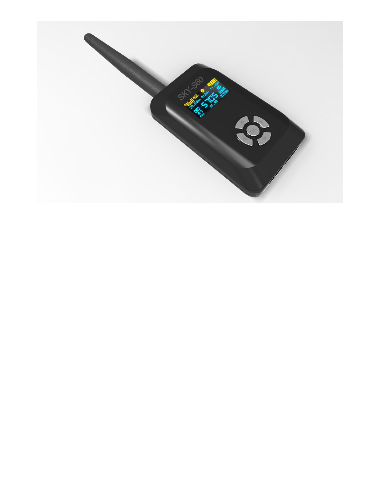
Skysighthobby Sky-S60 User manual

1/14
Long Range Wireless OSD 5.8G FPV
Transmitter
Built-in 10 Axis AHRS + MAVLINK + 600mW
Support all flight controller and GPS
2/14
User's Guide
Catalogue
Product Instruction……………………………………………………………………………3
Features…………………………………………………………………………………………3
Specifications………………………………………………………………………………….4
Channel Frequency……………………………………………………………………………5
Schematic Diagram……………………………………………………………………………5
Interface…………………………………………………………………………………………6
Button Function………………………………………………………………..............………6
OLED Display interface……………………………………………………………………….7
OSD Screen Display interface……………………………………………………………….7
Frequency and Channel Groups Setting………………………………………………….8
Home Setting……………………………………………………………………………………8
Switch OSD Panel with remote………………………………………………………………8

3/14
MODE 1: Using the built-in 10 axis AHRS…………………………………………………9
MODE 2: Using the built-in 10 axis AHRS + GPS…………………………………………10
MODE 3: MAVLINK Serial Data………………………………………………………………10
MODE 4: Skysight fly Controller…………………………………………………………….10
Set the Serial interface baud rate……………………………………………………………11
IMU self test………………………………………………………………………….…………11
IMU Calibrate……………………………………………………………………………………12
Reset Default setting……………………………………………………………………………13
View AHRS data………………………………………………………………………………….13
OSD ON/OFF………………………………………………………………………………………13
Warning…………………………………………………………………………………………….13
Packing List…………………………………………………………………………………………13
Product Instruction
Welcome to enjoy the Skysighthobby 5.8GHz Video Transmitter with OSD. Skyshighthobby
products have forged a reputation for quality and reliability and are tested and developed by FPV
pilots for FPV pilots. The SKY-S60 transmitter packs a whopping 600mw of ultra clean 5.8GHz
power! It can transmit a full range of 32 channels and comes with a clean pre-wired harness; it’s
perfect for any long range aircraft.
The SKY-S60 boasts an impressive new feature; with built-in OSD (On Screen Display). It provides
flight data output function such as satellite count, battery voltage, flight time, latitude/longitude,
altitude, horizontal distance, horizontal speed, vertical speed, and flight mode. It’s compatible to all
fly controllers.
Features:
●Dual color dot-matrix OLED display, high contrast and brightness, also visible under the sun,
direct frequency, channels and reference transmit power display, supply voltage and current
instructions, video mode instructions, the serial interface baud rate indicates

4/14
●Power: 600mW, >=1km open distance with 2dbi Omni-directional antenna
● Automatic video mode switching(NTSC/PAL)
● 2 OSD panel, 3 display modes (OSD panel 1, OSD panel 2, OSD off) switch with the remote
channel
● Built-in 10-axis AHRS attitude detect, contains a 3-axis accelerometer, 3-axis gyro meter, 3-axis
digital compass, barometric altimeter
● Support all of the flight controllers, easy to install and use
● Support MAVLINK protocols
● Support GPS
● Suitable for airplanes, cars, and boats
Specifications
Test conditions
Min
Typical
Max
Supply voltage
6.5V
12V
28V
Transmission
power
@T=25degrees
5705MHz
400mW
600mW
750mW
Antenna
connector
SMA Jack
Current
consumption
@voltage12V
NA
0.4A
0.6A
Temperature
range
-10 degrees
80 degrees
Voltage
accuracy
±0.05V
±0.1V
±0.5V
Video Bandwidth
5MHz
6MHz
6MHz
Impedance
75Ω/1Vp-p

5/14
Subcarrier
6.5MHz
Audio
Impedance
4.7KΩ
Gyroscope
errors
NA
Accelerometer
errors
NA
Electronic
compass errors
NA
Barometer errors
NA
Net weight
NA
Size
68x42x18 mm
Channel frequency table (32CH): (Unit of frequency: MHz)
A
B
C
D
1
5705
5733
5865
5740
2
5685
5752
5845
5760
3
5665
5771
5825
5780
4
5645
5790
5805
5800
5
5885
5809
5785
5820
6
5905
5828
5765
5840
7
5925
5847
5745
5860
8
5945
5866
5725
5880
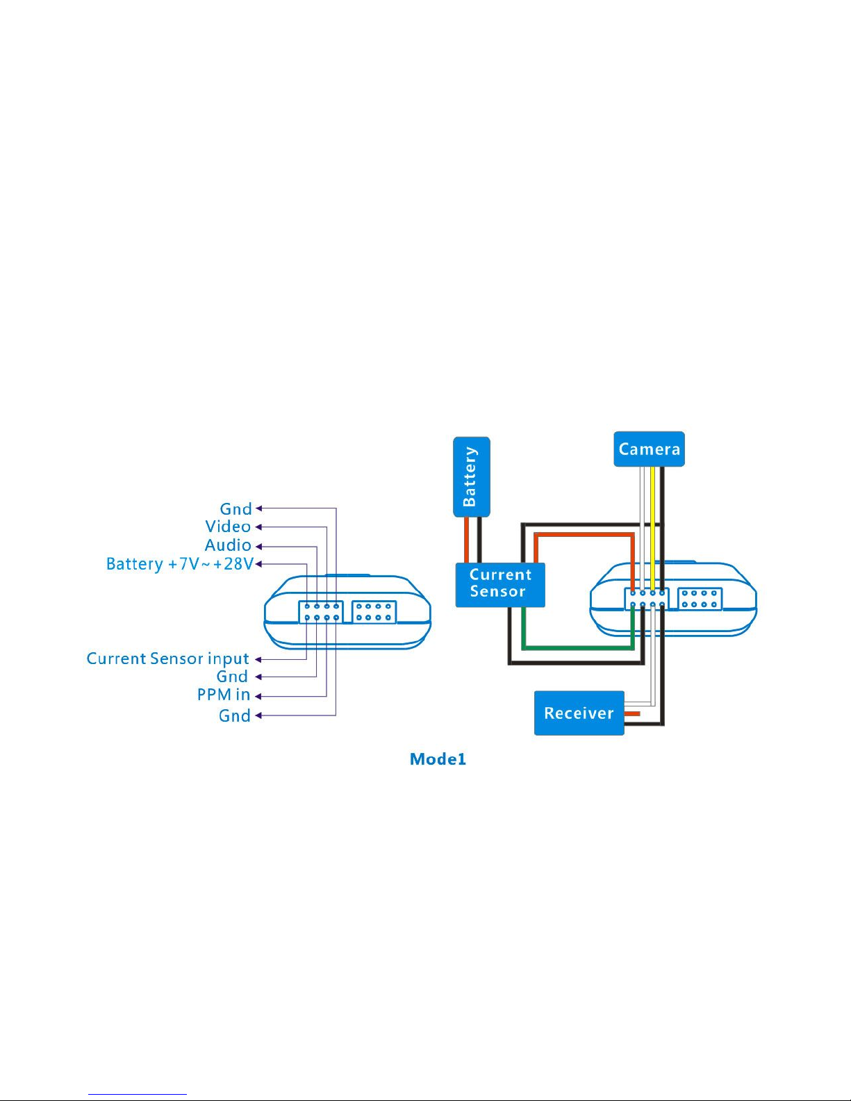
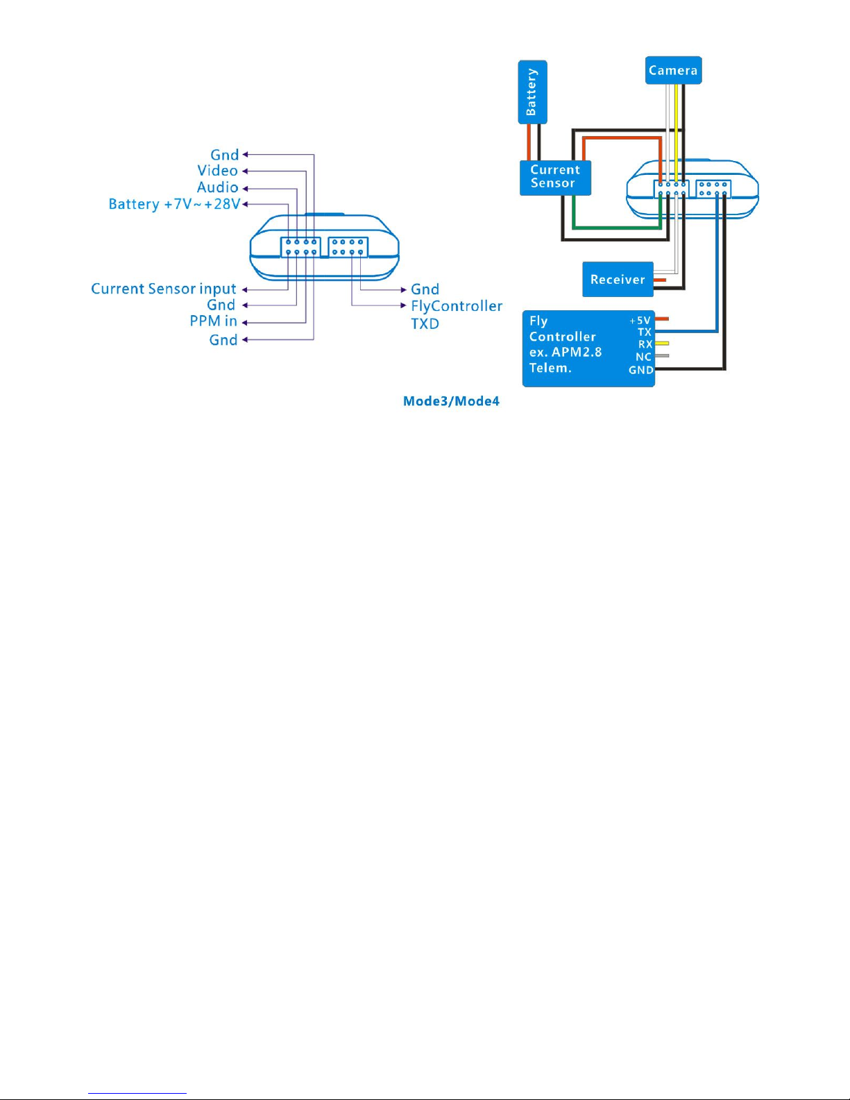
Schematic diagram:

6/14
Interface:

7/14
Button function:
Button ◀:
1. OLED main interface push to change the RF channel group
2. Menu interface , push back previous menu
Button ▶:OLED main interface push to change the RF channel
Button ▲:Up
Button ▼:
1. Down
2. Long press for 3 seconds Sets the current position to home
Button ●:Menu / Confirm
OLED Display interface:

8/14
Note :The RF power information on OLED display is PA chip detector power , not is actual
RF output power
OSD Screen display interface:
OSD panel 1:
OSD panel 2:

9/14
Frequency and channel groups setting:
At OLED main interface press button◀change channel groups
At OLED main interface press button▶change RF channel
Home Setting:
At OLED main interface long press button ▼ about 3 seconds setting the HOME
Switch OSD panel with remote:
Switching OSD panel need to connect PPM output signal with remote control receivers
Connect to PPM remote control receiver channel and GND wire in the figure below (Switch
OSD display mode)
10 /14
Using the remote control 3-band switch or joysticks can toggle the OSD panel interface
PPM<1.2ms is OSD off
PPM>1.8ms is OSD panel 2
other PPM>1.3ms and PPM<1.7ms is OSD panel 1
Mode 1: using the built-in 10 axis AHRS
Click OK,select Com Setting in the menu,select GPS in list Com Type,click OK to save
setting ,click ◀back
This mode is the easiest to use mode, users only need connect to the battery power, video,
audio, GND wire, without having to connect other devices, built-in AHRS provides attitude
message, for example: pitch angle, roll angle, heading direction, barometer etc.
This mode , geographic and distance(home distance) with no data
Mode 2: using the built-in 10 axis AHRS + GPS
Click OK,select Com Setting in the menu,select GPS in list Com Type,click OK to save
setting ,click ◀back
Click OK,select GPS Band rate in the menu , select the baud-rate for GPS in list , typical
GPS baud rate is 4800 or 9600 and 19200
This mode is mode 1 for additional,need connect to GPS module
Will be complete show all profile information, as well as the whole function of longitude,
latitude and distance display

11 /14
Mode 3: MAVLINK serial data
This mode only for MAVLINK protocol's flight controller, ex. APM flight controller
Need connected to flight control's digital transmit interface
Click OK,select Com Setting in the menu,select Mavlink in list Com Type,click OK to save
setting ,click ◀back
Click OK,select Mavlink Bandrate in the menu,select the baud-rate for flight controller's
Mavlink protocol in list , typical Mavlink protocol baudrate is 57600
Mode 4: Skysight flight controller
This mode only for Skysight flight controller
Click OK,select Com Setting in the menu,select Skysight in list Com Type,click OK to save
setting ,click ◀back
Click OK, select Skysight Bandrate in the menu , select the baud rate for Skysight flight
control in list , typical Skysight flight controller baudrate is 57600
12 /14
Set the serial interface baud rate
GPS Band rate Setting
Click OK,select GPS Band rate in the menu , select the baud-rate for GPS in list , typical
GPS baud rate is 4800 or 9600 and 19200
Mavlink Band rate Setting
Click OK,select Mavlink Band rate in the menu,select the baud-rate for flight
controller's Mavlink protocol in list , typical Mavlink protocol baud rate is 57600
PC Bandrate Setting
Click OK, select PC Bandrate in the menu , select the baudrate for PC debug in list , typical
PC debug baudrate is 57600
Skysight Bandrate Setting
Click OK, select Skysight Bandrate in the menu , select the baud rate for Skysight flight
control in list , typical Skysight flight controller baudrate is 57600
IMU Selftest
When use built-in 10-axis AHRS IMU, you need to do built-in IMU Selftest for the first time
use or after restoring the factory settings and the flight place is changed
Select IMU Selftest in the menu and press the OK , Selftest will begin after 10 seconds,
please hold in a quiescent state
13 /14
IMU Calibrate
When use built-in 10-axis AHRS IMU, you need to do built-in IMU calibrate for the first time
use or after restoring the factory settings and the flight place is changed
Select IMU Calibrate in menu and press OK , follow to the tips on OLED display,
press any buttons start calibration of accelerometer and gyroscope after 10 seconds , please
hold in a quiescent state , after accelerometer and gyro calibration is completed, OLED
screen will prompt calibration of data ,
after 5 seconds will enter the digital compass calibrate state
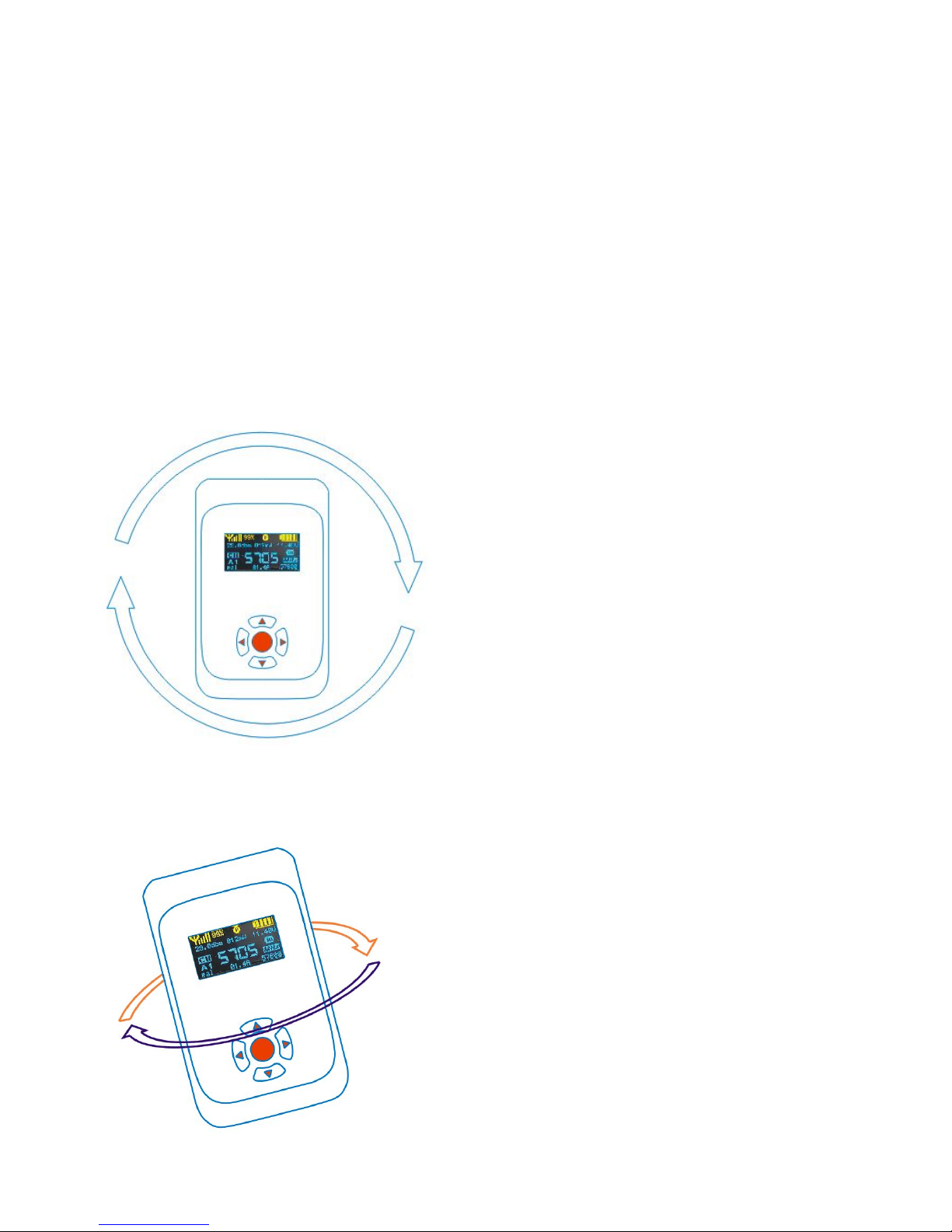
Compass Calibrate state
Follow the tips of OLED display, pressing any key will begin compass calibration, and that you must
to do rotating horizontally slowly at least once
And then do the following rotate once

14 /14
Calibrate will be finish in about 30 seconds
Reset Default Setting
Choose Reset Default in the menu and press the OK key, it will restore the factory settings
After restoring factory settings, depending on the connection mode, please configure the
serial data type and baud rate once again , do IMU self test and IMU calibrate if using the
built-in AHRS modules
View AHRS Data
Menu select View AHRS data and confirm , the IMU self test and calibrate values will be
display in OLED panel
OSD ON/OFF
Select OSD ON/OFF and confirm in the menu, to switch the OSD enable or disable
Warning:
Because the interface wiring much more , so please again to make sure wiring is correct,
incorrect connection may cause damage
Packing list:
OSD Transmitter*1
Cable set*1
Antenna*1
Table of contents
Popular Transmitter manuals by other brands


LRS
LRS T9550 LCK user manual

Q5X
Q5X PlayerMic Quick start guid

Listen Technologies
Listen Technologies ListenPoint LPT-T216 user manual

Critical Environment Technologies
Critical Environment Technologies LPT-A Series Operation manual

scope
scope Connexions CX4 Installation & user manual

Connevans
Connevans FmGenie How to use