Content
For your safety..................................................................................................................................................................................3
Technical data and information........................................................................................................................................................3
Operational conditions .....................................................................................................................................................................4
Terminology ......................................................................................................................................................................................4
Product desciption............................................................................................................................................................................5
Instalation, assembly and disassembly of the transmitter...............................................................................................................6
1. Assembly of the transmitter .................................................................................................................................................6
2. Replacement of the sensor module......................................................................................................................................6
3. Replacement of the battery..................................................................................................................................................6
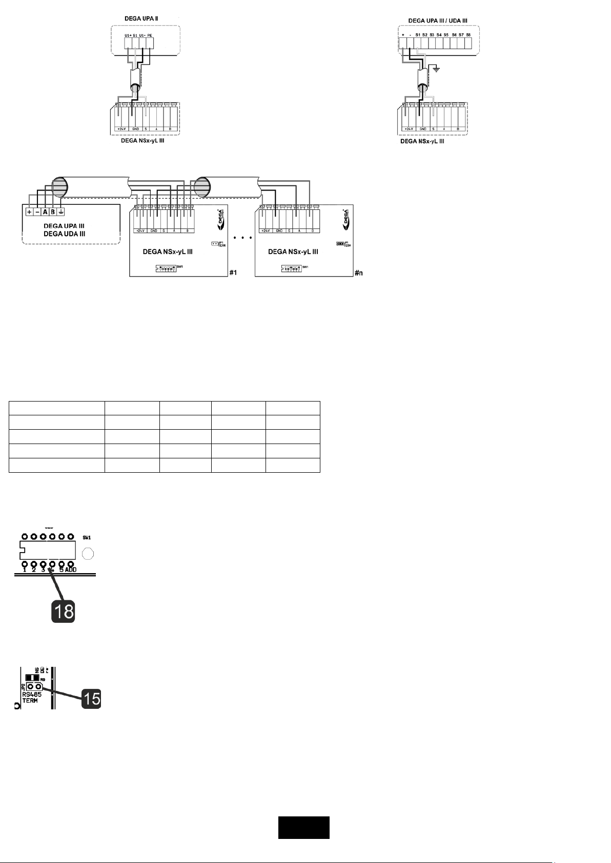
4. Connecting the transmitter via current loop to the controler DEGA UPA II DEGA UPA III a DEGA UDA III..........................6
5. Connecting the sensor via RS485 to the controller DEGA UPA III/UDA III............................................................................7
6. Installation of wiring for RS485.............................................................................................................................................7
Selecting the appropriate type of cable depends on the fire report and the protocol for determining external influences. ....7
7. Setting the RS485 adress of the transmitter.........................................................................................................................7
8. Terminating resistor..............................................................................................................................................................7
9. Communication protocol switch DEGA/MODBUS................................................................................................................8
Transmitter functions .......................................................................................................................................................................8
1. Turning on the transmitter ...................................................................................................................................................8
2. Gas detection........................................................................................................................................................................8
3. Malfunction...........................................................................................................................................................................8
4. Monitoring the calibration periods.......................................................................................................................................8
5. Reading the record of measured concentrations and alarms ..............................................................................................8
Operation, maintenance, inspection and service of the transmitter ...............................................................................................8
1. Usage limits...........................................................................................................................................................................8
2. Operation..............................................................................................................................................................................9
3. Operation/Maintenance.......................................................................................................................................................9
Accessories and basic types of transmitters.....................................................................................................................................9
1. Calibration adapter/connection to the gas pump DEGA GAS INLET ....................................................................................9
2. Cover against splashing water DEGA WATER CAP..............................................................................................................10
3. Funnel for gas collection DEGA COLLECT CAP ....................................................................................................................10
4. Additional Ex „d“ bushing DEGA VÝVODKApro NSxIII.........................................................................................................10
Basic types of transmitters .............................................................................................................................................................10
1. Transmitters with a catalytic sensor NSx-CL III...................................................................................................................10
2. Transmitters with an electrochemical sensor NSx-EL III.....................................................................................................10
3. Transmitters with an infrared sensor NSx-IL III...................................................................................................................12
4. Transmitters with a semiconductor sensor NSx-SL III.........................................................................................................13
5. Transmitters with a PID sensor NSx-PID III .........................................................................................................................13
Attachments....................................................................................................................................................................................13
1. Chart for setting the transmitter adress.............................................................................................................................13
2. Signalization transmitted by the current loop 4-20mA ......................................................................................................13
General warranty terms and conditions.........................................................................................................................................14