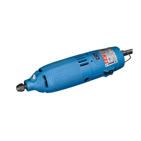
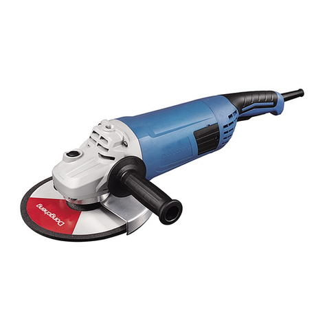
Dongcheng DSM125A User manual

Edition 4 Aug ., 2014
Read through carefully and understand these
instructions before use.

GENERAL POWER TOOL SAFETY WARNINGS
(For All Power Tools)
WARNING! Read and understand all instructions. Failure
to follow all instructions listed below may result in electric shock, fire
and/or serious personal injury.
Save all warnings and instructions for future reference.
The term “power tool”in the warnings refers to your mains-operated (corded)
power tool or battery-operated (cordless) power tool.
Work Area Safety
1. Keep work area clean and well lit. Cluttered or dark areas invite accidents.
2. Do not operate power tools in explosive atmospheres, such as in the
presence of flammable liquids, gases, or dust. Power tools create sparks
which may ignite the dust or fumes.
3. Keep children and bystanders away while operating a power tool.
Distractions can cause you to lose control.
Electrical Safety
4. Power tool plugs must match the outlet. Never modify the plug in anyway.
Do not use any adapter plugs with earthed (grounded) power tools.
Unmodified plugs and matching outlets will reduce risk of electric shock.
5. Avoid body contact with earthed or grounded surfaces, such as pipes,
radiators, ranges and refrigerators. There is an increased risk o electric
shock if your body is earthed or grounded.
6. Do not expose power tools to rain or wet conditions. Water entering a
power tool will increase the risk of electric shock.
7. Do not abuse the cord. Never use the cord for carrying, pulling or
unplugging the power tool. Keep cord away from heat, oil, sharp edges or
moving parts. Damaged or entangled cords increase the risk of electric shock.
8. When operating a power tool outdoors, use an extension cord suitable for
outdoor use. Use of a cordsuitablefor outdoor use reduces the risk of electric shock.
9. If operating a power in a damp location is unavoidable, use a residual current
device (RCD) protected supply. Use of an RCD reduces the risk of electric shock.
NOTE: The term “residual current device (RCD)” may be replaced by the term
“ground fault circuit interrupter (GFCI)” or “earth leakage circuit breaker (ELCB)”.
Personal Safety
10.Stay alert, watch what you are doing and use common sense when operating
a power tool. Do not use a power tool while you are tired or under the
influence of drugs, alcohol, or medication. A moment of inattention while
operating power tools may result in serious personal injury.
11.Use personal protective equipment. Always wear eye protection. Protective
equipment such as dust mask, non-skid safety shoes, hard hat, or hearing
protection used for appropriate conditions will reduce personal injuries.
12.Prevent unintentional starting. Ensure the switch is in the off-position before
connecting to power source and /or battery pack, picking up or carrying the
tool. Carrying power tools with your finger on the switch or energising power tools
that have the switch on invites accidents.
13.Remove any adjusting key or wrench before turning the tool on. A wrench or a
key left attached to a rotating part of the power tool may result in personal injury.
14.Do not overreach. Keep proper footing and balance at all times. This enables
better control of the power tool in unexpected situations.
15.Dress properly. Do not wear loose clothing or jewellery. Keep your hair,
clothing, and gloves away from moving parts. Loose clothes, jewellery or long
hair can be caught in moving parts.
16.If devices are provided for the connection of dust extraction and collection
facilities, ensure these are connected and properly used. Use of dust collection
can reduce dust-related hazards.
Power Tool Use and Care
17.Do not force the power tool. Use the correct power tool for your application.
The correct power tool will do the job better and safer at the rate for which it was
designed.
-1- -2-

18. Do not use tool if switch does not turn it on or off. Any power tool that
cannot be controlled with the switch is dangerous and must be repaired.
19. Disconnect the plug from the power source and/or the battery pack from
the power tool before making any adjustments, changing accessories, or
storing power tools. Such preventive safety measures reduce the risk of
starting the power tool accidentally.
20. Store idle power tools out of the reach of children and do not allow
persons unfamiliar with the power tool or these instructions to operate
the power tool. Power tools are dangerous in the hands of untrained users.
21. Maintain power tools. Check for misalignment or binding of moving parts,
breakage of parts and any other condition that may affect the power
tool’s operation. If damaged, have the power tool repaired before use.
Many accidents are caused by poorly maintained power tools.
22. Keep cutting tools sharp and clean. Properly maintained cutting tools with
sharp cutting edges are less likely to bind and are easier to control.
23. Use the power tool, accessories and tool bits etc. in accordance with
these instructions, taking into account the working conditions and the
work to be performed. Use of the power tool for operations different from
those intended could result in a hazardous situation.
Service
24. Have your power tool serviced by a qualified repair person using only
identical replacement parts. This will ensure that the safety of the power tool
is maintained.
VOLTAGE WARNING:
Before connecting the machine to a power source (receptacle, outlet, etc.), be sure
the voltage supplied is the same as that specified on the nameplate of the machine.
A power source with voltage greater than that specified for the machine can result
in SERIOUS INJURY to the user, as well as damage to the machine. If in doubt,
DO NOT PLUG IN THE MACHINE. Using a power source with voltage less than
nameplate rating is harmful to the motor.
SPECIFICATIONS
S1M-FF-125A
S1M-FF03-115
Rated Power Input
850 W
850 W
Rated Speed
11800 r/min
11800 r/min
Wheel size
External dia.
Thickness
Internal dia.
125 mm
6 mm
22 mm
115 mm
6 mm
22 mm
Net Weight
1.8 kg
1.8 kg
※Due to the continuing program of research and development, the specifications
herein are subject to change without prior notice.
ADDITIONAL SAFETY RULES
1. Ensure that the power switch is in the OFF position and unplugged before carrying
out any work on the tool.
2. Use your tool at lower input than specified on the nameplate; otherwise the finish
may be spoiled and working efficiency reduced by motor overload.
3. Never operate this power tool without wheel guard. Keep guards in place.
4. Use only wheels with maximum operating speed at least as high as “No-Load
Speed”indicated on the power tool nameplate. When using depressed center
wheels, be sure to use only fiberglass-reinforced wheels.
5. Check the wheel carefully for cracks or damage before operation. Replace cracked
or damaged wheel immediately.
6. Use only flanges specified for this tool.
7. Be careful not to damage the spindle, flanges (especially the installing surface) or
bolt. Damage to these parts could result in wheel breakage.
8. Keep hands away from rotating parts.
9. Make sure the wheel is not contacting the workpiece before the switch is turned on.
10.Before using the tool on an actual workpiece, let it run for a while. Watch for
vibration or wobbling that could indicate poor installation or a poorly balanced
-3- -4-

wheel.
11. Watch out for flying sparks. Hold the tool so that sparks fly away from you
and other persons or flammable materials.
12. Do not leave the revolving grinder unattended on the floor. Operate the tool
only when hand-held.
13. Avoid overload operation. Stop operation immediately if you notice anything
abnormal.
14. Do not push in the lock pin while the spindle is running.
15. Do not touch the workpiece immediately after operation; it may be extremely
hot and could burn your skin.
16. Do not work with materials containing asbestos.
17. To ensure the designed operational integrity of power tools, do not remove
installed covers or screws.
18. Be sure to use an earth-leakage circuit breaker (30mA), if work area is too
hot and wet or poisoned by electric dust.
SAVE THESE INSTRUCTIONS.
WARNING! MISUSE or failure to follow the safety rules stated in this
instruction manual may cause serious personal injury.
INSTRUCTIONS FOR OPERATION
Installing or Removing the Depressed Center Wheel
CAUTION:
Always be sure that the tool is switched OFF
and unplugged before installing or removing
the wheel.
Screw the inner flange onto the spindle. Press
the spindle lock firmly so that the spindle
cannot revolve, then use the lock nut wrench
to secure the inner flange. Fit the wheel on
over the inner flange and screw the outer
flange onto the spindle. (Fig.1)
To tighten the outer flange, press the spindle
lock firmly so that the spindle cannot revolve,
then use the lock nut wrench and securely
tighten clockwise. (Fig. 2)
CAUTION: There is a washer on the inner
flange, if it is lost or damaged be sure to fit a
new one before fit the inner flange onto the
spindle.
To remove the wheel, follow the installation procedures in reverse.
Mounting the Auxiliary Handle
For all work with the tool, the auxiliary handle
must be mounted.
Screw the auxiliary handle on the right or left
of the tool head. (Fig. 3)
Switch Operation
WARNING! Before plugging in the tool,
always check to see that the switch actuates
properly and returns to the “OFF”position
when the rear of the switch lever is
depressed.
To switch ON, depress the rear of the switch
lever and push it forward. Then depress the
front of the switch lever to lock it.
To switch OFF, depress the rear of the switch
-5- -6-

lever. (Fig. 4)
Operation
Hold the tool firmly, turn the tool on and then apply the wheel or disc to the
workpiece.
In general, keep the edge of the wheel
or disc at an angle of about 15°-30° to
the workpiece surface.
During the break-in period with a new
wheel, do not work the grinder in the B
direction, or it will cut into the
workpiece. Once the edge of the wheel
has been rounded off by use, the wheel
may be worked in both A and B
directions. (Fig. 5)
WARNING:
It should never be necessary to force the tool. The weight of the tool applies
adequate pressure. Forcing and excessive pressure could cause dangerous
wheel breakage.
Continued use of a worn-out wheel may result in wheel explosion and serious
personal injury. Depressed center wheel should not be used after it has been
worn down to 75 mm (3”) in diameter. Use of the wheel after this point is unsafe
and it should be removed from service and rendered unusable by intentional
destruction.
MAINTENANCE
CAUTION:
Always be sure that the tool is switched off and unplugged before attempting to
perform inspection or maintenance.
After use
Blow away dust from the inside of the tool by running the tool at an idle for a while.
Brush off accumulation of dust on the base.
Accumulation of dust in the motor or on the base may cause a malfunction of the tool.
Replacing carbon brushes
Remove and check the carbon brushes
regularly. Replace when they wear down to
the limit mark. Keep the carbon brushes
clean and free to slip in the holders. Both
carbon brushes should be replaced at the
same time. Use only identical carbon
brushes. (Fig. 6)
Use a screwdriver to remove the rear cover.
Disconnect the carbon brush from the brush
holder, then draw the Belleville spring and
take out the worn carbon bush and replace
new one; Release the Belleville spring and
reconnect each carbon brush with the brush
holder. And then tighten the rear cover
securely. (Fig. 7)
※Damaged cord must be replaced by a
special cord purchased from authorized service center.
※To maintain product SAFETY and RELIABILITY, repairs, any other maintenance or
adjustment should be performed by authorized centers, always using original
replacement parts.
-7- -8-

EXPLAINATION OF GENERAL VIEW
1
Bearing Cover (19×21.2×8.6)
26
Outer Flange
2
Ball Bearing 607ZZ
27
Inner Flange
3
Insulation Washer
28
Baffle Plate
5
Armature Assembly
29
Stator Assembly
6
Guide Plate
30
Switch Knob
7
Oil Seal (22×25.2×4)
31
Nameplate
8
Shim 17×8×0.3
32
Strain Relief
9
Ball Bearing 608DD
33
Pan Head Tapping Screw ST4.2×12
10
Driving Spiral Bevel Gear
34
Capacitor
11
Hex. Nut M6
35
Switch Assembly
12
Lock Nut
36
Compression Spring
13
Autolocking Spring 8.2×0.8×11
37
Switch Lever
14
Pan Head Tapping Screw ST4.2×25
38
Cord
15
Gear Housing
39
Cord Guard
16
Lock Pin
40
Pan Head Tapping Screw ST4.2×19
17
Needle Bearing HK0810
41
Rear Cover
18
Driven Spiral Bevel Gear
42
Carbon Brush
19
Circlip for Hole
43
Pan Head Tapping Screw ST2.9×9
20
Ball Bearing 6201DDW
44
Carbon Brush Holder
21
Bearing Box
45
Belleville Spring
22
Shim 28.5×12
46
Motor Housing
23
Pan Head Screw M6×16
48
Pan Head Screw M4×12
24
Wheel Cover(S1M-FF-125A)
861
Wrench
Wheel Cover(SIM-FF03-115)
862
Auxiliary Handle
25
Drive Spindle
-9- -10-
This manual suits for next models
3
Table of contents
Other Dongcheng Grinder manuals