DongFeng DFA1063DJ10-301 User manual

DONGFENG DFA1063DJ10(14)-301/303
SERVICE MANUAL
DONGFENG AUTOMOBILE CO., LTD.
September. 2006

INDEX
General Principles
Clutch
Gearbox
Propeller Shaft
Steering System
Front Axle
Rear Axle
Suspension System
Brake System
Cab
Electric System

General Principles
GL
Table of Conntents
General Principles...........................................................................................GL-1
Operational Instruction ...................................................................................GL-2
Standard Terms...............................................................................................GL-2
Standard Tightening Torque...........................................................................GL-2
Maintenance Rule ...........................................................................................GL-3
Recommended Fuel and Lubricant.................................................................GL-6
Protective Measures while Repairing .............................................................GL-8
Cleaning..........................................................................................................GL-9
Generic Inspection..........................................................................................GL-9
Trouble Analysis...........................................................................................GL-10

General Principles
GL-1
General Principles
This manual mainly states maintenance and service methods of DONGFENG DFA1063DJ10(14)-301/303
light commercial truck.
To use vehicles safely and efficiently, you need to read the manual thoroughly and make sure that you are
familiar with the items that mark "Note". This is very important.
Due to continuous improvements on our vehicles, maybe there are some instructions in the manual that do
not accord with the actual vehicles.
Maintenance method varies with different skill level, methods, tools and available parts that serviceman
adopts. Any serviceman should firstly take into consideration no harm personal safety and vehicle safety when
working.
As for the maintenance of engine, please refer to service documents offered by Dongfeng Cummins Engine
Co., Ltd.

General Principles
GL-2
Operational Instruction
You can neglect the structural differences between the part in the
manual and the corresponding one of your vehicle, because the manual
is just teaching you principles for your operation.
Standard Terms
Vehicle direction
Vehhicle direction referred in the manual is marked as the right
picture.
Maintenance standard
The matching clearance or standard performance parameter of
components while assembled.
Reparation limit
It means that the component size or component clearance after
repairing must satisfy the specified repair limit;
Wear limit
It means that if a component is overworn or exceeds its wear
limit, it must be replaced;
Unit
Legal measure units are used in this manual.
Standard Tightening Torque
To assure the safety and reliability of key vehicle parts, this
manual makes specific prescriptions to the tightening torque of the
bolts and other fasteners on those parts. As for the bolts and other
fasteners not mentioned, the structures and the sizes of them have been
standardized and they should be fastened with screwing torques
prescribed in the following table.
M6 M8 M10 M12 M14 M16 M18 M20
Ordinary car-
bon steel 5~8 16~23 29~42 50~70 80~110 130~170 160~200 260~320
High-strength
alloy steel 9~12 18~26 34~48 67~95 120~170 165~220 200~250 320~400

General Principles
GL-3
Maintenance Rule
Maintenance Schedule
It's necessary for periodical inspection and maintenance of truck to prolong its service life, improve its power
performance and fuel economy, so periodical inspection and maintenance should be carefully carried out accord-
ing to the following items. Then it will achieve the max economic and social benefits.
The following schedule is not only for maintenance items of 80,000km, but also for normal maintenance
items after 80,000Km.
△—maintenance mileage at running-in period (1,500~2,500km)
☆—maintenance items at running-in period
★—maintenance items at regular driving period
Note:
Customers should carry out the inspection and maintenance intervals according to the different area
condition. Properly shorten the maintenance intervals can ensure the truck to get the reasonable maintenance and
move reliability. Never prolong the intervals.
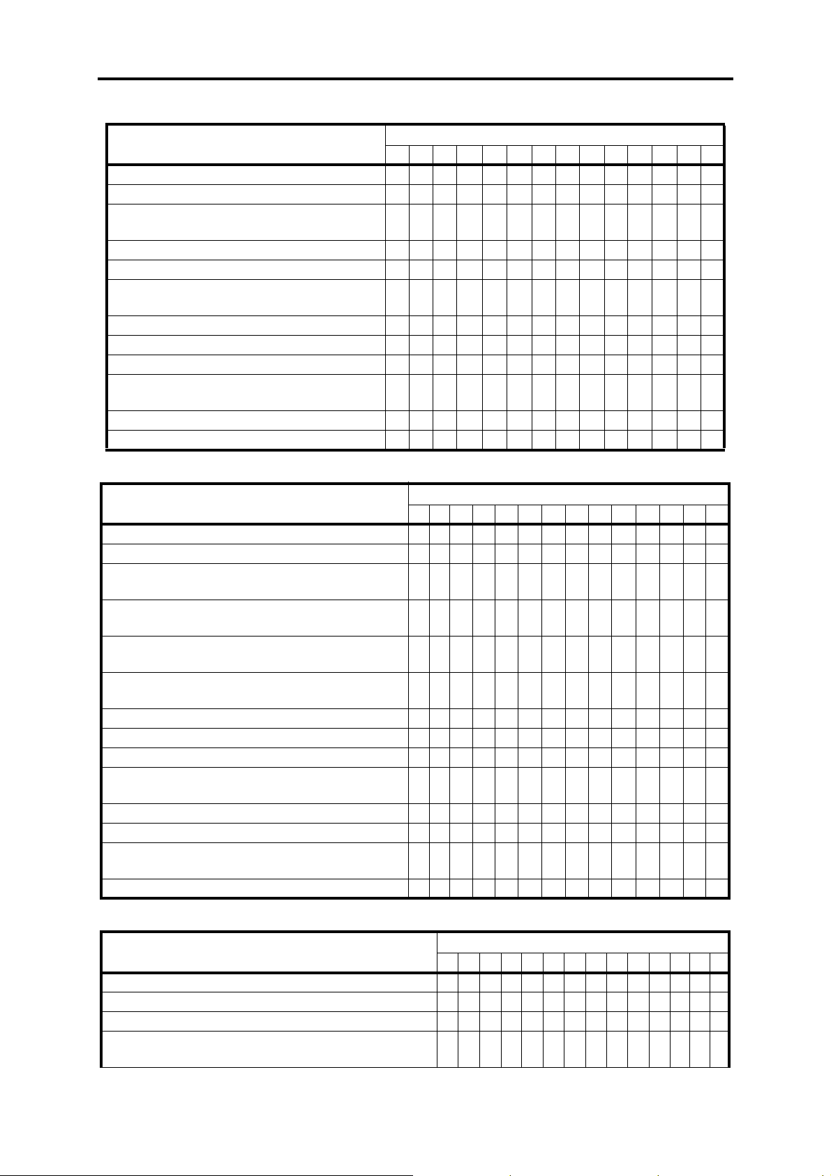
Dongfeng Cummins Diesel Engine
Maintenance Item Maintenance Mileage Interval( ×1,000km)
△4 8 12 16 20 24 28 32 36 40 44 48 80
Clean engine assembly ★★★★★★★★★★★★
Check acceleration capability and decelerability ☆★★★★★★★★★★★★
Check exhaust status ☆★★★★★★★★★★★★
Check the leakage of eninge lubricant ☆★★★★★★★★★★★★
Check the cleanness and reserves of lubricant ★★★★★★★★★★★★
Check the leakage of fuel ☆★★★★★★★★★★★★
Check the leakage in cooling system ☆★★★★★★★★★★★★
Check the damage of fan belt ☆★★★★★★★★★★★★
Remove the deposit in fuel prefilter ☆★★★★★★★★★★★★
Check and clean air filter element ☆★ ★ ★ ★ ★ ★
Replace engine lubricant ☆★ ★ ★ ★ ★ ★
Replace oil filter ☆★ ★ ★ ★ ★ ★
Check and adjust valve clearance ☆★★★★
Replace fule filter and oil & water seperator ★★★★
Replace air filter element ★★
Check the compression pressure in cylinder ★
Check the injection pressure of injector ★
Check injection timing ★
Check the injection volume of injection pump ★
Check the working conditions of delivery pump ★
Check the working conditions of thermostat ★
Check the working conditions of radiator ★
Clean the cooling system of engine ★
Check the working conditions of supercharger,
replace while necessary ★★

General Principles
GL-4
Clutch
Maintenance Item Maintenance Mileage Interval( ×1,000km)
△4 8 12 16 20 24 28 32 36 40 44 48 80
Check the working conditions of clutch ☆★★★★★★★★★★★★
Check the free travel of clutch pedal ☆★★★★★★★★★★★★
Check the leakage of the hydraulic pipeline and
clutch pump ☆★★★★★★★★★★★★
Check the air leakage of clutch booster ☆★★★★★★★★★★★★
Check the reserve of braking fluid in oil reservoir ☆★★★★★★★★★★★★
Replace clutch braking fluid ★
Propeller Shaft
Maintenance Item Maintenance Mileage Interval( ×1,000km)
△4 8 12 16 20 24 28 32 36 40 44 48 80
Check the looseness of the linking parts of propeller
shaft ☆★ ★ ★ ★
Check the looseness of spider bearing ☆★
Check the looseness of middle bearing ☆★
Check the wearing conditions of spline ★
Gearbox
Maintenance Item Maintenance Mileage Interval( ×1,000km)
△4 8 12 16 20 24 28 32 36 40 44 48 80
Clean gearbox and vent plug ☆★★★★★★★★★★★★
Check the oil reserves in gearbox ☆★★★★★★★★★★★★
Check oil leakage of gearbox ☆★★★★★★★★★★★★
Replace gearbox lubricant ☆★★
Check the looseness of the linking parts of the con-
trol mechanism ☆★★
Check the working conditions of the bearings in
gearbox ★
Disassemble and check gearbox ★
Suspension System
Maintenance Item Maintenance Mileage Interval( ×1,000km)
△4 8 12 16 20 24 28 32 36 40 44 48 80
Check the leakage of shock absorber and fasten the
bolts of brackets ☆★★★★ ★★★ ★ ★★★★
Clean front and rear leaf spring and shock absorber ★★★★★★★ ★ ★★★★
Fasten U bolt of leaf spring when fully loaded ☆★ ★ ★ ★
Check the damage and looseness of shock absorber ★★★★
Check the wearing of pin sleeve of rear leaf spring,
replace while necessary ★
Check if shock absorber is out of service ★
Disassemble leaf spring, replace spring pin and pin
sleeve ★

General Principles
GL-5
Axle and Wheel
Maintenance Item Maintenance Mileage Interval( ×1,000km)
△4 8 12 16 20 24 28 32 36 40 44 48 80
Clean alxes and wheels ★★★★★★★★★★★★
Check the oil leakage of final drive ☆★★★ ★★★★★★★★★
Check the fastening conditions of important
bolts ☆★★★★★★★★
Check the pressure in tyres ☆★★★ ★★★★★★★★★
Check the abnormal wearing of wheels ★★★★★★★★★★★★
Check lubricant reserves of final drive, clean
vent plug ★★★★
Clean and adjust hub bearings ★★★★
Replace the lubricant of final drive ☆★★
Wheel changing ★★★★
Check the working conditions of final drive and
the bearings ★
Disassemble and check final drive and adjust it ★
Make megnatic examination for axle shaft tube ★
Steering system
Maintenance Item Maintenance Mileage Interval( ×1,000km)
△4 8 12 16 20 24 28 32 36 40 44 48 80
Check the oil leakage of steering gear ☆★★ ★ ★ ★ ★ ★ ★ ★ ★ ★ ★
Clean steering gear ★★★★ ★ ★ ★ ★ ★ ★ ★ ★
Check free travel and working conditions of hand
wheel ☆★ ★ ★ ★
Check the fastening conditions of the ball heads of
steering cross rod and tie rod ☆★ ★ ★ ★
Check fastening conditions of steering mechanism
and its brackets ☆★ ★ ★ ★
Check fastening conditions of steering arm and steer-
ing knuckle arm ☆★ ★ ★ ★
Check and adjust front wheel toe-in ☆★ ★ ★ ★
Check front wheel alignment ★
Check and adjust steering gear ★
Disassemble and check the connectors of steering
cross rod and tie rod ★
Make magnetic examinations for steering knuckle ★
Replace the ball head pins in steering system ★
Check power steeering oil reserves, add while neces-
sary ☆★★ ★ ★ ★ ★ ★ ★ ★ ★ ★ ★
Replace power steering transmission oil ★★
Braking System
Maintenance Item Maintenance Mileage Interval( ×1,000km)
△4 8 12 16 20 24 28 32 36 40 44 48 80
Check the free travel of brake pedal ☆★★★★★★★★★★★★
Check parking brake and its efficiency ☆★★★★★★★★★★★★
Check the air leakage of braking pipeline ☆★★★★★★★★★★★★
Check and adjust the clearance between brake drum and
friction disc ☆★★★★★★★★★★★★★

General Principles
GL-6
Recommended Fuel and Lubricant
The quality of fuel and lubricant can effect the performances, quality and even life of vehicles. Therefore, to
ensure normal operations of vehicles, suitable oil products should be used according to relative prescriptions.
DongFeng Automobile Co., Ltd. prescribes the most suitable fuel and lubricants for its products. The foll-
wing are the fuel and lubricants that should be used in our products.
Fuel
Qualified light diesel in accord with GB252—87 Standard should be used. Users can choose specific class of
light diesel according to the specific temperature in his region.
Recommended temperature scope:
Engine lubricant
High-quality lubricant meeting following standards must be used for Dongfeng Cummins engines:
Lowest standard:CF-4/SG 15W-40
Recommended Standard:CG-4/SH 15W-40
Ideal standard:CH-4/SJ 15W-40
Check the fastening conditions of brake back plate ☆★★★★
Check the wearing of brake drum and shoe, replace while
necessary ★★
Check the working conditions of air compressor ★
Other
Maintenance Item Maintenance Mileage Interval( ×1,000km)
△4 8 12 16 20 24 28 32 36 40 44 48 80
Check battery liquid reserves, add while necessry ☆★★★ ★ ★ ★ ★ ★ ★ ★ ★ ★
Check the proportion of battery liquid ★★★★
Check the looseness of the rivets in chassis frame ★★
Check the efficency of locking device of titing mech-
anism ★★
Check the looseness of linking parts of cabin ☆★★★ ★ ★ ★ ★ ★ ★ ★ ★ ★ ★
Check and adjust latches of cargo body ☆★★★ ★ ★ ★ ★ ★ ★ ★ ★ ★
Check the looseness and damage of cross and side
members of cargo body and the linking parts ★★
Check the wearing of latches, replace while neces-
sary ★
Class Recommended Temperature
0# light diesel above 4 ℃
10# light diesel above -5 ℃
20# light diesel between -5 ℃~ -14 ℃
35# light diesel between -14 ℃~ -29 ℃
50# light diesel between -29 ℃~ -44 ℃
Braking System
Maintenance Item Maintenance Mileage Interval( ×1,000km)
△4 8 12 16 20 24 28 32 36 40 44 48 80

General Principles
GL-7
Note:
Engine damages for using lubricants below CD15W-40 or CE15W-40 or even lower are not in our warranty
scope.
Suitable temperature scope:
For 15W-40: -10 ℃~-15 ℃; For 10W: -5 ℃~-20 ℃; For 5W-30: below -25 ℃
Lubricant for gears in driving axle
Recommend to use sulfur-phosphor API GL-5 gear lubricant for heavy duty vehicle. Applicable
environment temperatures for different classes are as follow:
Gearbox oil
Recommend to use sulfur-phosphor 85W/90 GL-4 gear lubricant for middle duty vehicle.
Lubricating grease
Recommend to use generally-used lithium grease for the lubricating points on hubs and chassis frame.
Shock absorber oil
Recommend to use specially-used shock absorber oil.
Clutch boosting liquid
Recommend to use DOT 4 compounded braking liquid. Different classes of braking liquid can not be used
together.
Note:
Braking liquid made by different manufacturers can not be used together.
Engine antifreeze liquid (coolant)
Recommend to use long-term antirust & antifreeze liquid. The freeze point of the antifreeze liquid used
should be 8 ℃lower than the minimum local temperature. Different classes of antifreeze liquid can not be used
together.
Volume Data
Part Vo l u m e (L)
Fuel tank 120
Engine lubrication system 9
Engine cooling system 14.5

General Principles
GL-8
Protective Measures while Repairing
To assure safety in repairing, the following protective measures
should be taken all the way:
1)Before reparation, you should ensure that the wheels can not
turn. The measure to lock wheels is as the sketch map.
2)Ensure that the gearbox is at neutral position.
3)Ensure that the ignition switch is at "off" postion.
4)When repairing electric circuit, the negative pole should be
disconnected.
5)The jacks and brackets used should be strong enough for the
load acting on them.
Method of mounting brackets is as the sketch map.
The supporting points of front axle for mounting jacks is as the
sketch map.
The supporting points of rear axle for mounting jacks is as the
sketch map.
Gearbox 4.2
Rear axle Add till the oil overflow from the inspection hole
Clutch Add to the scale of "MAX" of clutch oil reservoir
Power steering gear Add between the upper and lower scale of oil tank
Volume Data
Part Vo l u m e (L)

General Principles
GL-9
6)When disassemble or assemble the assemblies that have been taken down, you should ensure that they are
on a solid worktable to avoid they would drop or turn over.
Cleaning
Because the parts may be covered by dirty oil and mud, cleaning is compulsive.
Applicable cleaning methods include steam cleaning, pressure cleaning, light oil cleaning, acid or alkali
cleaning, neutral medium cleaning, trichlorethylene steam cleaning, Magnus solution cleaning, etc. Part damages
may be revealed during the cleaning, so great attention should be paid while cleaning.
Metal parts
Light oil: in contrast with other solutions, light oil can't penetrate or dissolve mud. Therefore, except for
finished surface, mud should be removed by wire brush or other tools and should be cleaned in this way for two
times.
Alkali solution: if the parts are made of alloy, don't use alkali solutions for the cleaning. Instead, alkali
solutions are very effective for the cleaning of steel and cast iron.
Note:
If alkali solutions are being used, you should make some correctives such as boric acid solution. Once your
eyes or skin touch the alkali solution, you should use the corrective to clean.
Rubber parts
Don't use mineral oil for the cleaning. Use alcohol or clean cloth to remove the mud.
Oil duct
Make a metal wire to get through the oil duct to ensure it is not jammed. Wash the oil duct with cleaning
solution with high-pressure nozzle.
Antirust
After removing the oil grease on the parts, clean grease should be applied to prevent the rusting of the parts.
General Inspection
Check parts and components with special gauges or tools. Decide whether a component can continue to
serve according to specified maintenance standards. Damaged components should be repaired or replaced as
required. If one of a pair of components fitted together is worn so much that the fit clearance exceeds the specified
range, replace the pair of components together.
Out of consideration of preventive maintenance, some components should be replaced before them reaching
service limit.
Carefully inspect the surface of components by outlook or red check method. Repair or replace the compo-
nent if its surface has the following abnormal signs: uneven wear, biased wear, scratch, crack, distortion, malfunc-
tion or becoming weak (spring), bended, loose, abnormal noise (bearing), distortion, malfunction or becoming
weak (spring), bended, loose, abnormal noise (bearing), discolored, seized, eroded, deteriorate (friction lining),
etc.
All the rubber pieces, such as O-rings, oil seals and washers cannot be further used after disassembled.

General Principles
GL-10
Trouble Analysis
In a vehicle, a part is made up of many components. Some parts like clutch, transmission and rear axle are
interactive functioning. Therefore, in order to find and examine trouble exactly, it is necessary to know the struc-
ture of each part as well as the functional connection between various parts.
To resolve a problem of the vehicle, you must first know the nature of the trouble. To achieve this, you must
get some exact knowledge of the trouble from the customer, including the parts that effect using conditions and
the date of the happening of the trouble.
A trouble may be caused by one or many reasons in most cases. Therefore, to examine and repair requires
the ability of systematic thinking and resolving problems step by step. For example, when the steering wheel turns
unstable, you should first examine the connection mechanism of the pitman arm instead of disassembling the
steering gear rashly, then decide whether the trouble belongs to the steering gear or to the connection mechanism.
When disassembling the part to find the cause of the trouble, proceed systematically and start from easy
problem.
It is a very important way to find out the cause of the trouble according to the manifestation of the trouble
such as abnormal noise, vibration and failure. Listed below are some common trouble signs and their reasons. As
for the detailed trouble analysis, please refer to chapter of each assembly.
1. During starting of the engine (neutral position)
2. After engine started
3. During starting of vehicle
Engine can
not start
Listen to the sound of the gear of the
gear of the starter Folo-tru drive No sound Trouble in starting system
Having sound Engine troubled
Abnormal sound Engage a gear Sound does not stop Clutch cover troubled
Engine troubled
Exhaust system troubled
Sound stops Clutch driven disc troubled
Transmission troubled
Abnormal sound Clutch troubled
Transmission troubled
Propeller shaft troubled
Rear axle troubled
Engine drive belt slipped

General Principles
GL-11
4. During vehicle running
Unstable running of vehicle Engine troubled
Incomplete release of parking brake
Incomplete release of brake
Bumpy running of vehicle Clutch troubled
Overload of propeller shaft
Engine rubber mounting failed
Poor acceleration Clutch slipped
Incomplete release of brake
Incomplete release of parking brake
Engine fuel system troubled
Abnormal noise Continuous noise Transmission troubled (oil insufficient or deteriorate)
Reductor gear troubled (oil insufficient or deteriorate)
Wheel hub bearing troubled (grease insufficient or
improper)
Over-low tyre pressure
Noise Transmission troubled
Reductor gear troubled
Propeller troubled
Noise when run on road bend Differential gear troubled
Noise when brake Brake troubled
Too heavy vibration Front and rear leaf spring troubled
Shock absorber troubled
Propeller shaft troubled
Engine troubled
Uneven wear of tyre or imbalance of tyres
Engine mounting troubled
Cab mounting troubled
Unstable running (straight) Incorrect front wheel alignment
Front axle troubled
Suspension spring troubled
Steering system troubled
incomplete release of brake
Uneven tyre pressure

General Principles
GL-12
Abnormal steering operation Heavy steering Steering system troubled
Incorrect front wheel alignment
Front axle troubled
Over low pressure of front wheel
Turning wheels not return Steering system troubled
Incorrect front wheel alignment
Front axle troubled
Insufficient steering angle Steering system troubled
Front axle troubled
Abnormal gear shift Difficult gear shift Abnormal clutch disengagement
Transmission troubled
Transmission handling mechanism troubled
Gear disengaged Transmission troubled
Transmission handling mechanism troubled
Abnormal braking operation Weak braking Brake system troubled
Overwear of tyres
Hub bearing clearance too large
Brake can't be released completely Brake system troubled
Hub bearing clearance too large

Clutch
CL
Table of Contents
Main Parameter............................................................................................... CL-1
Clutch Mechanical System ............................................................................. CL-2
Adjustment of Clutch Pedal............................................................................ CL-3
Clutch Cover and Flywheel ............................................................................ CL-6

Clutch
CL-1
Clutch
Main Parameter
Note:
The DOT4 compound brake fluid is recommended to the clutch.
Unclean or dirty brake fluid is forbidden to use.
Do not splash the brake fluid down to the paint. (It may erode the paint.)
You must make use of the tools to disassemble and assemble the clutch pipeline system.
Make use of the clean brake fluid to clean the master cylinder, booster and the fluid reservoir.
The mining oil such as gasoline, kerosene, etc., it will erode the rubber parts in the hydraulic pressure sys-
tem.
After clean the clutch pressure plate, dry it with the suction cleaner, not the compression air.
Bolt install hole size
Distributing diameter (mm) Φ379
Aperture (mm) Φ10.5 (+0.27)
Number of holes 8 (4 pairs)
Positioning pin hole size
Distributing diameter (mm) Φ384
Aperture (mm) Φ9.5 (+0.061, +0.025)
Φ7.9 (+0.061, +0.025)
Number of holes 2
Angle between positioning hole and installing bolt hole 10°
Friction lining size D×dΦ325×Φ200
Working pressure force 11300±13500
Release bearing stroke (mm) 10~11.5
Pressure plate lift range (mm) ≥1.5
Height of release finger (mm) 56±1.6
Unbalance static of the cover assembly (g.cm) ≤70
Unbalance static of the driven disc assembly (g.cm) ≤35
Torque (N.m) Mmax=1087

Clutch
CL-2
Clutch Mechanical System
Clutch Control Mechanism
1.Clutch pedal bracket assy
2.Lower fixed plate--pedal bracket
3.Clutch pedal welding assy
4.Protective sheath--pedal
5.Clutch pedal shaft
6.Return spring--clutch pedal
7.Bush--pedal assy
8.Pin
9.Clutch master pump assy

Clutch
CL-3
Clutch Control Pipeline
Adjustment of Clutch Pedal
1.Adjust the height of the clutch pedal by adjusting the pedal setting bolt. The height of clutch pedal is about
160~170mm.
2.Adjust the free stroke of the clutch pedal.
Release bearing
Check the release bearing for any crack or wear. The release bearing must be smooth and turn without noise.
Replace it if necessary.
Check the release sleeve and release fork for wear, damage or erode, and replace if necessary.
Bearing lubricating
Make use of the recommended lubricant for the connecting surface and the attrition surface of bearing and
fork.
Note:
Overmuch lubricant may cause clutch driven disc damaged.
1.Clutch master pump assy
2.Front oil pipe assy--clutch master pump to slave
pump
3.Straight joint
4.2nd front oil pipe assy--clutch master pump to
booster
5.Hose bracket
6.Front hose assy--clutch
7.Rear oil pipe assy--clutch master pump to
booster
8.Clutch rear oil pipe bracket
9.Rear hose assy--clutch
10.Booster assy
11.Nylon hose assy
12.Oil reservoir assy

Clutch
CL-4
Clutch driven disc and pressure plate
Clutch driven disc
1.Rivet--friction disc
2.Rivet--catch plate
3.front damping disc
4.Friction disc
5.Damping fin
6.Driven disc clamping plate
7.Driven disc
8.Driven disc rivet
9.Wave spacer
10.Wave spacer rivet
11.Disc hub set
12.Spline disc
13.Damping spring1
14.Damping spring2
15.Rear damping disc
16.Half ring pressure board
17.Catch plate
18.Damping spring--idle speed
19.Spring spacer
20.Guard shield
This manual suits for next models
3
Table of contents
Other DongFeng Truck manuals