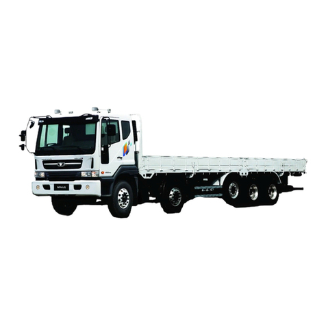
Komatsu HM300-3 User manual

ARTICULATED
DUMP TRUCK
Field Assembly Instruction
GEN00111-03
HM300-3
SERIAL NUMBERS 3001 and up

1 Drawings of removed units .............................................................
.
1
2 Dimensions of removed units ..........................................................
.
1
3 Assembly procedure, necessary equipments, and schedule .......
.
2
4 Necessary tools and equipments ....................................................
.
2
5 Assembly procedure No. .................................................................
.
3
0010 Installation of the slin
g
...........................................................
.
3
0100 Positionin
g
bare machine ......................................................
.
4
0110 Installation of rear monitor .....................................................
.
5
0120 Rear monitor ad
j
ustment 1 ....................................................
.
6
0130 Rear monitor ad
j
ustment 2 ....................................................
.
7
0140 Rear monitor ad
j
ustment 3 ....................................................
.
8
0150 Rear monitor ad
j
ustment 4 ....................................................
.
9
0200 Installation of mirrors .............................................................
.
10
0210 Installation of cab step
g
uards ............................................... 11
0220 Installation of ri
g
ht and left mud
g
uards .................................. 12
0300 Ad
j
ustin
g
N2
g
as of front and rear suspensions .................... 13
0310 Installation of antenna ............................................................ 14
0400 Assembly of ADT :Installation of bearings (If equipped).....
.
15
0410 Assembly of ADT :Installation of side arm (If equipped).....
.
16
0420 Assembly of ADT :Installation of tail gate (If equipped)....... 17
0430 Assembly of ADT :Installation of tail gate (If equipped)...... 18
0440 Assembly of ADT :Installation of tail gate (If equipped)...... 19
0500 Connectin
g
of hoist c
y
linder ................................................... 20
Attached sheet: Mirror ad
j
ustment procedure ....................................
.
21
Contents

1 Drawings of removed units
Specifications of HM300-3 completed truck
【】・・・ Wide tire spec.
2 Dimensions of removed units
No.
1 Bare machine
【】・・・ Wide tire spec.
24,910 【25,500】
Self-propelled travel
Unit name Weight (kg)
24,910 【25,500】
Overall length (mm) Overall width (mm)
3,510 【3,495】
(Weight of machine) (When empty)
10,275 2,900 【3,282】
Specifications
Weight (kg) Overall length (mm) Overall width (mm)
Related items
Overall height (mm)
Overall height (mm)
3,510 【3,495】2,900 【3,282】10,275
1. Bare machine
2. Fender step L.H. 3. Fender guard L.H. 4. Fender guard L.H.
1

3 Assembly procedure, necessary equipments, and schedule
Day
Hour
(1) Positioning bare machine
(2) Installing engine hood mirrors
(3) Adjusting N2 gas of front and rear suspensions
(4) Inspection
Meeting before work Completion of assembly
Unloading
Starting assembly
4 Necessary tools and equipments
(1) Necessary tools
(2) Necessary equipments
Remarks
4
2
123
Number of workers
1st day
Assembly Procedure No. No.0100-0310
Assembly unit
No. Q'ty
11
21
31
Tool name Specifications Remarks
Ring wrench 19mm For installing hood mirror and front cover
Paint spray can Clear For touching up bolt head
Suspension gas pouring tool 7926-10-1000 For adjusting suspension pressure
No. Q'ty
11
Equipment name Specifications Remarks
Stepladder (Work stand) 4steps (About 1.5m) For work
2

1. Positioning bare machine
2. Preparation of the sling
1. Place protective plate when installing sling.
2. Detail of slinging on front side.
Q’ty Name Q’ty
Nylon sling 15ton 3 Crane: Min. 25-ton 2
When slinging the machine
Use protective plates not to damage the exterior
parts when installing sling tools.
Sling tools should not contact the side bumper
on front frame side when slinging the machine.
(It may damage the bumper)
No.0010 Installation of the sling
Cautions
Assembly procedure No.
Other
Necessary EquipmentSpecial tool
Name
1. Positioning on the flat ground Lock the machine by using a lock bar
Protective plate
When using a double wire
Sling tools are perpendicular. Do not interfere the side bumper
When using single wire
Perform slinging with sling angle 60 deg.
Protective plate
3

1. Positioning bare machin
e
1. Lower the bare machine from the trailer and position it on the flat ground.
Q't
y
Name Q't
y
Necessary equipmentNecessary tools
Others
No.0100
Name
Positioning bare machine
Precautions
Assembly procedure No.
4

Q't
y
Name Q't
y
No.0110 Installation of rear monitor
Necessary equipment
Assembly procedure No.
Necessary toolsPrecautions
Others
Name
Rear camera seen from above
Y
1. Install the rear monitor assembly as shown above.
2. Connect the rear monitor cable.
Q'ty State of parts (Parts list No.)
① 1 Separately Packed (M33-05-010)
② 3 Separately Packed (M33-05-010)
③ 1 Temporarily installed to rear lamp bracket
④ 1 Temporarily installed to rear lamp bracket
Part No. Part name
7835-33-2000 REAR MONITOR ASSEMBLY
04434-50610 CLIP
01024-80616 BOLT
01024-80616 BOLT
①②
View Y
Z
③④
View Z
Connect:
CN BMN
Rear camera
5

1. Enter the service menu.
5. Perform initialization.
2. Select Default.
3. Select Rear View Monitor Setting.
4. Select Rear View Monitor Initialize.
Assembly procedure No. No.0120 Rear monitor adjustment 1
HM300
Setting procedure of rear view monito
r
< User menu display method >
Press on standard screen Standard screen
Switch panel Luminance Adjustment switch
Rear view
monitor
While pressing , press in
order.
To No. 0130 Rear View Monitor Adjustment- 2
6

6. Return to the first screen (standard screen).
11. Select Rear View Monitor Setting.
7. Enter User menu and select Rear View Monitor Setting.
12. Select Guide Line Position Adjustment.
8. Turn off reverse-interlock enabled mode.
9. Return to first screen, then enter Service menu.
10. Select Default.
Assembly procedure No. No.0130 Rear monitor adjustment 2
( Rear view monitor is always displayed, even if shift
lever is not in " R ")
後進連動選択モード
リヤ
HM300
To No. 0140 Rear View Monitor
Adjustment-3
Guide Line Position Adjustment
While pressing , press
in order.
02 Guide Line Position Adjustment
7

* Decide horizontal and vertical positions on main monitor, then adjust position with this luminance adjustment
switch while watching rear view monitor.
* Perform only horizontal position adjustment in points 3 and 4 (since they are not related to rear end of body)
.
13. Select point from Guide Line Position Adjustment.
14. Select Horizontal Adjustment in Point 1 and adjust
to tire outside width with Luminance Adjustment switch.
15. Select Vertical Adjustment in Point 1 and adjust
to body rear end with Luminance Adjustment switch.
16. Screen returns to point selection screen.
Adjust guide line positions of points 2 to 4 similarly.
No.0140
Assembly procedure No. Rear monitor adjustment 3
Point 1
Point 3
Point 2
Point 4
Horizontal Adjustment
Vertical Adjustment
Guide Line Position Adjustment method
< Luminance
Adjustment
switch >
< Luminance
Adjustment
switch >
Rear View MonitorMain Monitor
Adjust to tire outside width
Adjust to body rear end
After setting all points, go to
No. 0150 Rear monitor adjustment-4
8

17. Return to first screen and enter User menu.
18. Select Rear View Monitor Setting.
19. Turn on guide line display.
Turn on Reverse-interlock enabled mode.
Assembly procedure No. No.0150 Rear monitor adjustment 4
後進連動選択モード
ON
ON
リヤ
Reference Line
Press on standard screen
If guide line is displayed as shown at right only
when shift lever is in R1 or R2, rear view monitor
setting is completed
* If body rear end guide line is displayed yellow, No. 0120
5. "Rear View Monitor Initialize" may not be performed.
[Reference] Relationship between
guide line and machine
Body rear end
( Red )
Tire outside width
( Green ) Tire outside width
( Green )
9

1. Installation of mirrors
1. Remove bolts tightened to each guard temporarily.
2. Remove a stay from guard and install it in reverse.
3. Adjust the angle of the mirror.
★To adjust, see Operation and Maintenance Manual.
Q'ty Name Q'ty
Ring wrench (19mm) 1 Stepladder (Work stand) 1
Name
Assembly procedure No.
Necessary equipmentNecessary toolsPrecautions
Others
No.0200 Installation of mirrors
①②③
They are temporarily installed to guard Install a stay reversely together with a mirro
r
Q'ty State of parts (Parts list No.)
①1 Temporarily installed to chassis
②1 Temporarily installed to chassis
③2 Temporarily installed to chassis
Part No. Part name
56D-54-31190 STAY
56D-54-32551 MIRROR
01024-81025 BOLT,SEMS
10

1. Install cab step guards
1. Remove bolts installed to guard and fender temporarily.
2. Install guards and step to fender.
Q'ty Name Q'ty
Installation of cab step guards
Precautions
Assembly procedure No.
Others
No.0210
Name
Necessary equipmentNecessary tools
Q'ty State of parts (Parts list No.)
①1 Separately Packed (M33-05-020)
②2 Temporarily installed to chassis
③1 Separately Packed (M33-05-020)
④2 Temporarily installed to chassis
⑤1 Separately Packed (M33-05-020)
⑥4 Temporarily installed to chassis
01024-81245
56D-54-37350
01024-81245
GUARD
BOLT,SEMS
GUARD
BOLT,SEMS
STEP
BOLT,SEMS
56D-54-37340
01024-81245
56D-54-37330
Part No. Part name
⑥
①②
③④
⑤
⑥
Direction cautions
The longer one is a front side.
11

1. Install mudguards to the right and left fenders.
1. Remove bolts and plates installed to fender temporarily.
2. Install guards to fender.
Q'ty Name Q'ty
Ring wrench (19mm) 1 Stepladder (Work stand) 1
Name
Precautions
Others
Assembly procedure No. No.0220 Installation of right and left mudguards
Necessary equipmentNecessary tools
FWD
FWD
③
③
①②
④
④
Q'ty
State of parts (Parts list No.)
①1 Temporarily installed to chassis
②1 Temporarily installed to chassis
③2 Temporarily installed to chassis
④6 Temporarily installed to chassis
Part namePart No. GUARD,L.H
GUARD,R.H
PLATE
BOLT,SEMS
56D-54-32960
56D-54-32950
56D-54-22970
01024-81025
12

1. Adjusting N2 gas of front and rear suspension
s
Adjust the quantity of N2 gas (front and rear, 4 places).
Q'ty Name Q'ty
Suspension gas pouring tool 1
(7926-10-1000)
Others
No.0300 Adjusting N2 gas of front and rear suspensions
Precautions Necessary tools Necessary equipment
Name
Assembly procedure No.
2. Pour nitrogen gas in the right and left suspension
cylinders simultaneously.
3. Do not extend the suspension cylinders to the
5. When the suspension cylinders rise to the specified level shown above, close the valve. (Pour the gas to the front suspension
cylinders until they rise to the level indicated by the decalcomania. Pour the gas to the rear suspension cylinders until they rise
to the level shown in the above figure.)
6. Remove the hoses from the nitrogen gas pouring valves and move the machine forward and in reverse to the suspension cylin-
ders and then stop without applying the brake. (Finally, stop the machine without applying the brake to prevent an uneven load
caused by braking.)
7. Apply the parking brake and check the length of the suspension cylinders.
8. If the length of the suspension cylinders is out of the standard range, repeat steps 3 -7. (Usually, adjustment is completed by
stroke end.
4. After moving the machine forward and in reverse,
stop it without applying the brake.
5. Do not steer the machine before finishing this
Adjustment. (If it is steered, the piping may be broken.)
1. Bleed air from the cylinders.
1. Loosen the air bleeding valves of the right and left front suspension cylinders and bleed air thoroughly. (Check that air does not
come out any more (and only oil flows out) and tighten the valves again. Tightening torque: 39.2 - 49.0 Nm {4 - 5 kgm})
2. Check that the valves are closed and install the suspension gas pouring tool to the gas cylinder.
3. Connect the hoses of the suspension gas pouring tool to the nitrogen gas pouring valves. (Since there are 2 hoses, connect
them to the right and left suspension cylinders and pour the nitrogen gas simultaneously so that pressure will be applied to both
cylinders evenly.)
4. Open the valve of the suspension gas pouring tool gradually.
repeating those steps 3 - 4 times.)
Front suspension cylinder
N2 gas pouring valve
Before adjusting suspension gas,
remove the cover. After adjusting install it.
Installing position of suspension gas
pouring tool
A
←Chassis side
Axle side →
Rear suspension cylinder
Air bleeding valve
Air bleeding valve
←Chassis side
Axle side →
A
When cylinder is retracted fully: MIN (83 ± 1mm)
Specified quantity of filled oil: OIL 113 ± 3mm
When empty: EMPTY (163 ± 10mm)
When cylinder is extracted fully: MAX (196 ± 1mm)
Dimension A (Front side)
When cylinder is retracted fully: MIN (31 ± 1mm)
Specified quantity of filled oil: OIL 51 ± 3mm
When empty: EMPTY (101 ± 5mm)
When cylinder is extracted fully: MAX (121 ± 1mm)
Dimension A (Rear side)
Before adjusting suspension gas,
remove the cover. After adjusting install it.
N2 gas pouring valve
Installing position of suspension gas
pouring tool
13

1. Install antenna to top of cab.
1. For KOMTRAX specification, install antenna to top of cab.
2. For radio specification, install antenna to left top of cab.
Q'ty Name Q'ty
Others
No.0310
Name
Assembly procedure No. Installation of antenna
Necessary equipmentNecessary toolsPrecautions
②
Z
View Z
①
Remove vinyl and
install antenna.
Remove cap and
install antenna.
Q'ty State of parts (Parts list No.)
① 1 Separately Packed (M33-05-050)
② 1 Separately Packed (M33-05-060)
Part No. Part name
8A13-10-2100 ANTENNA
20Y-06-41990 ANTENNA
14
ApplyLocktiteNo.262
orequivalent.

1. Install the bearings to the dump body.
Q’ty Name Q’ty
Sales code :4HCTG17A-E:ADT tail gate
(4HCTG25A-E:ADT tail gate KIT)
Assembly procedure No. No.0400 Assembly of ADT :
Installation of bearings (If equipped)
Name
Special toolCautions Necessary Equipment
Other
A
A
①
②
③
Section view A-A
④⑤
※Work on right and left sides
similarly Detail of P
※⑤Tightening torque:455~565Nm
(46.5~58kgm)
No. Part No. Part Name Q'ty State of part (Parts list No.)
①56E-83-27150 BRACKET 2 Separately Packed (M33-T5-040)
②567-50-11450 BEARING 2 Separately Packed (M33-T5-040)
③04065-08025 RING-SNAP 2 Separately Packed (M33-T5-040)
④01010-82050 BOLT 8 Separately Packed (M33-T5-040)
⑤01643-32060 WASHER 8 Separately Packed (M33-T5-040)
Section view F-F
15

1. Install the side arm.
Q’ty Name Q’ty
Sales code :4HCTG17A-E:ADT tail gate
(4HCTG25A-E:ADT tail gate KIT)
Assembly procedure No. No.0410 Assembly of ADT :
Installation of side arm (If equipped)
Other
Name
Special toolCautions Necessary Equipment
A
A
①
②
Plate side
③
Sponge side
④⑤
⑥
⑧
⑨
Apply G2-LI ③
⑦
※①Tightening torque:455~565Nm
(46.5~58kgm)
Detail of P
※Work on right and left sides
similarly
No. Part No. Part Name Q'ty State of part (Parts list No.)
①56D-83-36120 ARM,L.H 1 Separately Packed (M33-T5-040)
②56D-83-36130 ARM,R.H 1 Separately Packed (M33-T5-040)
③56B-83-16460 WASHER 4 Separately Packed (M33-T5-040)
④56D-83-16160 SEAL 2 Separately Packed (M33-T5-040)
⑤56E-83-27210 PIN 2 Separately Packed (M33-T5-040)
⑥56B-83-16490 WASHER 2 Separately Packed (M33-T5-040)
⑦01010-82045 BOLT 2 Separately Packed (M33-T5-040)
⑧01643-32060 WASHER 2 Separately Packed (M33-T5-040)
⑨07020-00000 FITTING 2
Section view A-A
16

1. Install the tail gate.
2. Adjust the distance between the stoppers welded to the side arm and dump body.
Q’ty Name Q’ty
Sales code :4HCTG17A-E:ADT tail gate
(4HCTG25A-E:ADT tail gate KIT)
Assembly procedure No. No.0420 Assembly of ADT :
Installation of tail gate (If equipped)
Other
Necessary Equipment
Name
Special toolCautions
①
②
④
⑤
⑥
D
D
Section D-D
☆clearance 7.5 +3
0
* Adjust and install shim (2) so that the clearance between the stopper
plates welded to the tail gate arm and dump body is the dimension
marked with ☆.
⑤
t= 3.2
a
a
bb
※
Z
View Z
☆Standard shim thickness 6㎜
Tightening torque:
235~285Nm
(23~28.5kgm)
No. Part No. Part Name Q'ty State of part (Parts list No.)
①56D-83-36111 GUARD,TAILGATE 1 Separately Packed (M33-T5-040)
②56D-83-36240 PLATE(t=3.2)10 Separately Packed (M33-T5-040)
③01010-81680 BOLT 16 Separately Packed (M33-T5-040)
④01643-31645 WASHER 32 Separately Packed (M33-T5-040)
⑤01580-11613 NUT 16 Separately Packed (M33-T5-040)
17
Table of contents

Other Komatsu Truck manuals
Komatsu
Komatsu 830E-1AC Manual

Komatsu
Komatsu 830E-AC Install guide

Komatsu
Komatsu 730E Manual

Komatsu
Komatsu HD325-8 Manual

Komatsu
Komatsu 960E-1 - Install guide

Komatsu
Komatsu 930E-4 Manual

Komatsu
Komatsu 730E User manual

Komatsu
Komatsu HM400-1 User manual

Komatsu
Komatsu 730E Manual

Komatsu
Komatsu HD785-5 Manual

Komatsu
Komatsu 830E-AC User manual

Komatsu
Komatsu 530M Manual

Komatsu
Komatsu HD785-7 Install guide

Komatsu
Komatsu ecot3 HM350-2 User manual

Komatsu
Komatsu HD325-7R Manual

Komatsu
Komatsu HD465-7 User manual

Komatsu
Komatsu HM300-2R User manual

Komatsu
Komatsu Galeo HM350-1 User manual

Komatsu
Komatsu Galeo HD405-7 User manual

Komatsu
Komatsu 930E-4 User manual