SealMaster CRACK PRO 60 User manual

S:\Engineering\13-Operator Manuals\Current\CRACKPRO_GRAVITY_V2.0_JUNE2019.docx
CRACK PRO GRAVITY FLOW
Owner’s Manual
Version 2.0
Issue Date: June 2019
Effective Date: April 2019
Version
Date
Changes
Approval
1.0
Original Issue
2.0
6/19
New Format and Updates
DS

Table of Contents
CORRESPONDENCE................................................................................................ 3
SealMaster® LIMITED WARRANTY ........................................................................ 4
SAFETY PRECAUTIONS AND CAUTIONS................................................................. 5
PRECAUTIONS..................................................................................................... 5
CAUTIONS........................................................................................................... 5
FIRST AID ............................................................................................................ 6
MANUAL COVERAGE............................................................................................. 7
CRACK PRO® GRAVITY FLOW .............................................................................. 7
CRACK PRO® DIRECT FIRE MELTER...................................................................... 7
OPERATING INSTRUCTIONS - DIESEL FUEL BURNER ............................................. 8
CHECKLIST........................................................................................................... 8
BEFORE STARTING THE ENGINE .......................................................................... 8
STARTING THE ENGINE ....................................................................................... 9
STARTING TEMPERATURE CONTROL..................................................................10
ADDING MATERIAL ............................................................................................12
MATERIAL TEMPERATURE .................................................................................12
POURING MATERIAL ..........................................................................................13
OPERATING INSTRUCTIONS - LP GAS BURNER.................................................... 14
CHECKLIST..........................................................................................................14
BEFORE STARTING THE ENGINE .........................................................................14
STARTING THE ENGINE ......................................................................................15
OPERATING INSTRUCTIONS - LP GAS BURNER.................................................... 16
LP GAS BURNER PICTURES .................................................................................17
STARTUP............................................................................................................18
ADDING MATERIAL ............................................................................................18
MATERIAL TEMPERATURE .................................................................................18
POURING MATERIAL ..........................................................................................20

2
MACHINE MAINTENANCE ................................................................................... 21
MAINTENANCE SCHEDULE.................................................................................21
TROUBLESHOOTING DIESEL FUEL BURNER ........................................................22
TROUBLESHOOTING LP GAS BURNER ................................................................23
HYDRAULIC OIL SHEET......................................................................................... 24
SAFETY DATA SHEET............................................................................................ 26
WIRING DIAGRAMS............................................................................................. 32
TEMPERATURE CONTROL BOX...........................................................................32
WIRING DIAGRAMS............................................................................................. 33
ELECTRIC BRAKES AND RUNNING LIGHTS ..........................................................33
MACHINE PICTURES AND PARTS LIST ................................................................. 34
PARTS LIST PICTURE-1........................................................................................35
PARTS LIST PICTURE-2........................................................................................37
PARTS LIST PICTURE-3........................................................................................39
PARTS LIST PICTURE-4........................................................................................41
PARTS LIST PICTURE-5........................................................................................43

3
ThorWorks Industries, Inc.
Purchased by __________________________ Model NO. _______________________
Company Name _______________________ Serial NO. _______________________
Address ________________________________ Acceptance Date ________________
City _____________ State______ Zip _______
CORRESPONDENCE
All Correspondence regarding this equipment, as well as general correspondence should be addressed to:
ThorWorks Industries, Inc.
PO Box 2277
Sandusky, OH 44870
In referring to the equipment, kindly state the Model Number, Serial Number and any part number involved
`

4
SealMaster® LIMITED WARRANTY
SealMaster warrants that its products are of quality material and workmanship. SealMaster
agrees to replace, within a period of one (1) year from date of delivery, or at its option, repair,
without charge, any part of their manufacture which proved defective. The repair or
replacement will be free of charge F.O.B. Sandusky, Ohio, proving the damaged part or parts
are returned, freight prepaid, to SealMaster and investigation show such repair or replacement
is made necessary by an inherent defect of material or workmanship.
It is hereby understood that engines, motors, pumps, or other components purchased by
SealMaster for use on its equipment are not warranted by SealMaster and are sold only with
the standard warranty of the manufacturer of that component.
SealMaster will make no allowances for repairs or alterations completed by outside sources
unless authorization is in writing and approved by an authorized SealMaster representative.
Any claims for defective material or workmanship must be made prior to the expiration of thirty
(30) days from the date failure occurs, and in all cases prior to the expiration of the warranty
period of one (1) year. It is the intent of this paragraph to limit SealMaster’s liability solely to
the cost of replacement parts, F.O.B. factory, or at the option of SealMaster to repair of the
defective part or parts. No allowances for damages, lost time, or any other claim will be
recognized.
This warranty is null and void if other than genuine SealMaster parts are used.
SealMaster is constantly striving to improve their products. Changes in design and
improvement will be made whenever the manufacturer believes the efficiency of the product
will be improved, without incurring any obligation to incorporate such improvements in any
machines which have been shipped or are in service.
In an effort to continue to improve product quality, SealMaster reserves the right to change
specifications without notice.
Any modification or alteration of this machine without prior approval of the manufacturer may
void this warranty.

5
SAFETY PRECAUTIONS AND CAUTIONS
PRECAUTIONS
•Always wear eye and ear protection, long sleeve shirt, face shield
and gloves.
•Be aware of all CAUTION, WARNING, DANGER signs on the unit.
•Read all Owners Manuals that come with this unit.
•Make sure the operator is familiar with the units’ operation.
CAUTIONS
•Keep hands, feet, and clothing away from moving parts.
•Do not operate the machine without all guards in place.
•Stop the Agitator when opening the lid for any reason.
•Never fill the fuel tank with a lit burner.
•WARNING! When checking oil levels, never check when HOT!

6
SAFETY PRECAUTIONS AND CAUTIONS
FIRST AID

7
CRACK PRO® GRAVITY FLOW AND DIRECT FIRE MELTER
APPLIES TO ALL DIESEL FUEL BURNER & LP GAS BURNER
MANUAL COVERAGE
CRACK PRO® GRAVITY FLOW
This manual covers the oil jacketed CRACK PRO® model sizes 60,125 and 260 gals.
CRACK PRO® DIRECT FIRE MELTER
This manual also covers the non-oil jacketed CRACK PRO® model size 125 gallons.
Because there is not an oil jacket, the burner reacts differently.
Upon turning on the temperature control, the burner blower motor will come on
for a second and then shut off. The burner control is now sensing all parameters.
It will take upward of two minutes for this to happen, and once all parameters are
met, the burner will fire, starting the heating cycle.
Every time the temperature control calls for heat, the burner will go thru this
two-minute cycle.
8
CRACK PRO® GRAVITY FLOW AND DIRECT FIRE MELTER
APPLIES TO ALL DIESEL FUEL BURNERS
OPERATING INSTRUCTIONS - DIESEL FUEL BURNER
STARTUP
CHECKLIST
•Check engine oil level. Follow manufacturers guidelines as to
type and frequency of changes.
•Check hydraulic oil level. Use grade AW68 hydraulic oil.
•Check heat transfer oil level with oil dipstick #25. Use a good
quality grade 68 turbine oil or heat transfer oil.
NEVER CHECK WHEN HOT!
•Fill fuel tank with gasoline for the engine.
•Fill fuel tank with diesel for the burner.
NEVER FILL FUEL TANK WITH A LIT BURNER!
•NOTE: Direct Fire Melter’s do not have heat transfer oil or oil
thermometer.
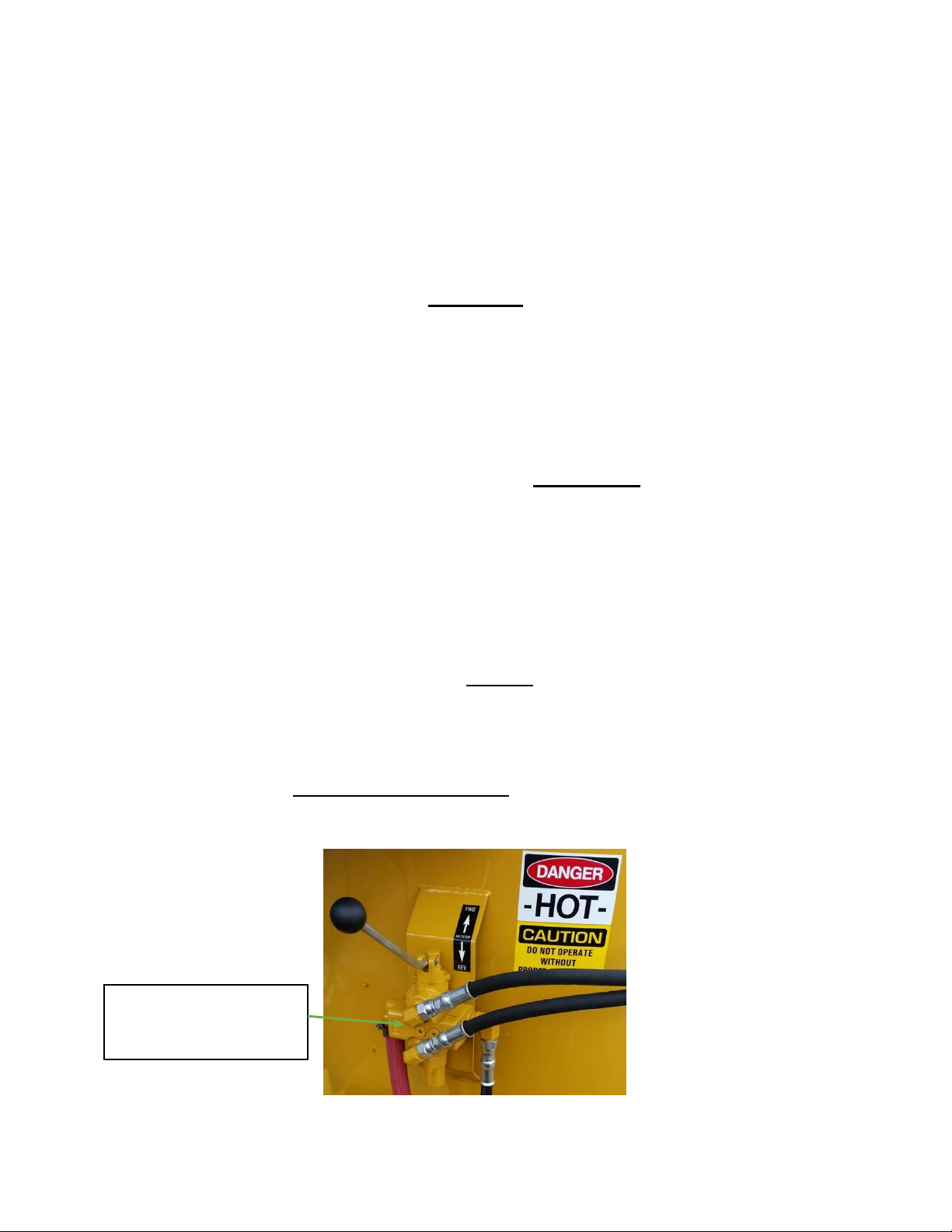
BEFORE STARTING THE ENGINE
Make sure the agitator control valve #23 is in the neutral position.
23 AGITATOR
CONTROL VALVE

9
CRACK PRO® GRAVITY FLOW AND DIRECT FIRE MELTER
APPLIES TO ALL DIESEL FUEL BURNERS
OPERATING INSTRUCTIONS - DIESEL FUEL BURNER
STARTUP
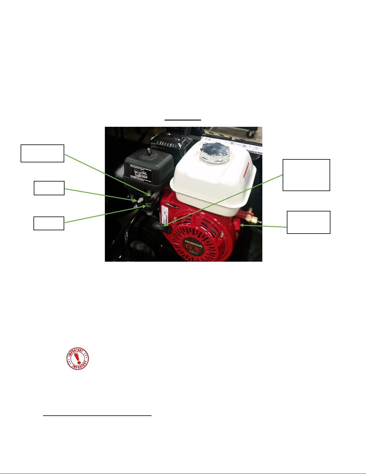
STARTING THE ENGINE
•Set the fuel shutoff and choke levers to the on position.
•Set the throttle lever at ½ open.
•Turn the engine switch to the start position.
•It is important that when you are done running the engine
that the fuel shutoff lever is turned to the off position. This keeps
gasoline from mixing with oil as you are driving.
Refer to the engine manual.
ENGINE
SWITCH
CHOKE
FUEL
THROTTLE
10
CRACK PRO® GRAVITY FLOW AND DIRECT FIRE MELTER
APPLIES TO ALL DIESEL FUEL BURNERS
OPERATING INSTRUCTIONS - DIESEL FUEL BURNER
STARTUP
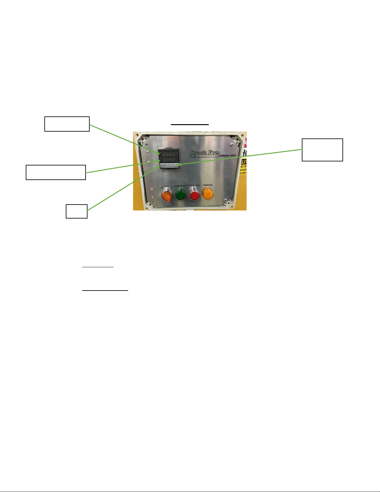
STARTING TEMPERATURE CONTROL
•The top scale is the ambient temperature of the heat transfer oil or
material temperature for SM-125.
•The bottom scale is the set temperature that you want the oil to be heated
to or material temperature for SM-125.
•NOTE: For SM-125 Refer to recommend pouring temperature on the
material box.
•The burner shuts off when your setting is exceeded by 10°.
•It comes back on when the temperature drops to 10° under your setting.
•The sequence for setting 475° temperature is:
1) Press the left arrow 3 times, then up or down for the 4.
2) Press the left arrow again, then up or down for the 7.
3) Press the left arrow again, then up or down for the 5.
4) Press SET.
NOTE: Factory set temperatures: CP Gravity Oil - 475° / SM-125 Material - 375°
ARROW
SETTINGS
BOTTOM SCALE
SET
TOP SCALE
11
CRACK PRO® GRAVITY FLOW AND DIRECT FIRE MELTER
APPLIES TO ALL DIESEL FUEL BURNERS
OPERATING INSTRUCTIONS - DIESEL FUEL BURNER
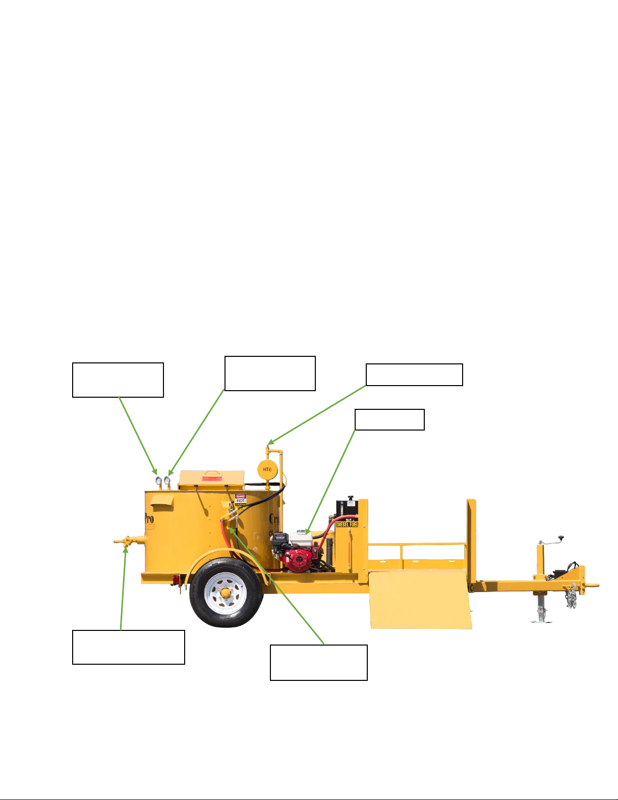
23 AGITATOR
CONTROL VALVE
21 ENGINE
16 MATERIAL
THERMOMETER
15 OIL
THERMOMETER
30 MATERIAL
DISCHARGE VALVE
25 OIL DIP STICK

12
CRACK PRO® GRAVITY FLOW AND DIRECT FIRE MELTER
APPLIES TO ALL DIESEL FUEL BURNERS
OPERATING INSTRUCTIONS - DIESEL FUEL BURNER
ADDING MATERIAL
1. Open the material tank lid and place three boxes of material
inside. Close the lid.
MATERIAL TEMPERATURE
2. When the material thermometer #16 and the oil thermometer
#15 reaches 300°, engage the agitator control valve #23 to the
forward position. If the agitator will not turn, return the valve
to the neutral position. Try again in a few minutes.
3. NOTE: When there are a few inches of liquid material in the
tank, you can add more blocks.
CAUTION: ALWAYS STOP THE AGITATOR WHEN OPENING THE
LID FOR ANY REASON!
4. As the material temperature gets close to the recommended
pouring temperature, you need to lower the digital
temperature controller setting down so that the material
thermometer #16and the oil thermometer #15 readings are
close together. When constantly adding blocks of material, the
digital temperature should be set about 50° higher than the
material pouring temperature.
5. If the material temperature starts to climb over the
recommended pouring temperature, open the lid and add
more blocks. Leaving the lid open will also help drop the
temperature.

13
CRACK PRO® GRAVITY FLOW AND DIRECT FIRE MELTER
APPLIES TO ALL DIESEL FUEL BURNERS
OPERATING INSTRUCTIONS - DIESEL FUEL BURNER
POURING MATERIAL
6. Set pour pot or applicator under the material discharge valve
#30 and raise the handle to open.
CAUTION: ALWAYS WEAR LONG SLEEVE SHIRT, GLOVES, AND
A FACE SHIELD WHEN PERFORMING THIS OPERATION!
7. Fill the crack filler pour pot to the desired level and pour into
cracks. Follow with a V-shaped squeegee if desired.
8. To stop for the day, perform the following steps:
•Turn the burner control switch to the off position, at least
a 1/2 hour before completing work.
•Put agitator control valve #23 in neutral.
•Shut off the engine #21.
BURNER CONTROL
SWITCH

14
CRACK PRO® GRAVITY FLOW AND DIRECT FIRE MELTER
APPLIES TO ALL LP GAS BURNERS
OPERATING INSTRUCTIONS - LP GAS BURNER
STARTUP
CHECKLIST
•Check engine oil level. Follow manufacturers guidelines as to
type and frequency of changes.
•Check hydraulic oil level. Use grade AW68 hydraulic oil.
•Check heat transfer oil level with oil dipstick #25. Use a good
quality grade 68 turbine oil or heat transfer oil.
NEVER CHECK WHEN HOT!
•Fill fuel tank with gasoline.
NEVER FILL FUEL TANK WITH A LIT BURNER!
•Check if the agitator control valve is in the neutral position.
•NOTE: Direct Fire Melter’s do not have heat transfer oil or oil
thermometer.
BEFORE STARTING THE ENGINE
Make sure the agitator control valve #23 is in the neutral position.
23 AGITATOR
CONTROL VALVE
15
CRACK PRO® GRAVITY FLOW AND DIRECT FIRE MELTER
APPLIES TO ALL LP GAS BURNERS
OPERATING INSTRUCTIONS - LP GAS BURNER
STARTUP
STARTING THE ENGINE
•Set the fuel shutoff and choke levers to the on position.
•Set the throttle lever at ½ open.
•Set the engine on/off switch to on position.
•Pull start the engine.
•It is important that when you are done running the engine
that the fuel shutoff lever is turned to the off position. This keeps
gasoline from mixing with oil as you are driving.
Refer to the engine manual.
CHOKE
FUEL
THROTTLE
ON/OFF
SWITCH
ENGINE
PULL START
HANDLE

16
CRACK PRO® GRAVITY FLOW AND DIRECT FIRE MELTER
APPLIES TO ALL LP GAS BURNERS
OPERATING INSTRUCTIONS - LP GAS BURNER
16 MATERIAL
THERMOMETER
15 OIL
THERMOMETER
25 OIL DIP STICK
21 ENGINE
23 AGITATOR
CONTROL VALVE
30 MATERIAL
DISCHARGE VALVE
30 MATERIAL
DISCHARGE VALVE
17
CRACK PRO® GRAVITY FLOW AND DIRECT FIRE MELTER
APPLIES TO ALL LP GAS BURNER
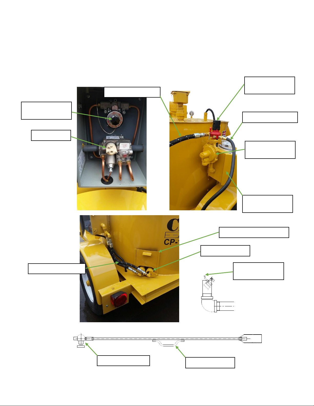
LP GAS BURNER PICTURES
9GAS VALVE
8TEMPERATURE
CONTROL
3HAND TORCH
REGULATOR
4LP GAS HOSE 1/4”
2LP GAS HOSE 1/2”
6MAIN BURNER
REGULATOR
7TEMPERATURE
CONTROL BOX
11 NEEDLE VALVE
12 GAS BURNERS
10 LP GAS HOSE 1/2”
5HAND TORCH
31 BURNER ACCESS DOOR
14 PILOT LIGHT
ASSEMBLY

18
CRACK PRO® GRAVITY FLOW AND DIRECT FIRE MELTER
APPLIES TO ALL LP GAS BURNERS
OPERATING INSTRUCTIONS - LP GAS BURNER
STARTUP
1. Open the temperature control box #7, and turn the temperature control
knob #8 all the way clockwise to its lowest setting. This will prevent the
burners from lighting prematurely. Remove burner access door #31.
2. Open the LP gas tank valve.
3. Turn the pilot knob on the gas valve #9 to the pilot position. Light the
hand torch #5 and place it in the burner opening. Position it by the pilot
light assembly #14, depress the pilot knob and remove the hand torch
when you see that the pilot flame is lit. Hold the pilot knob in for at least
30 seconds. Release the knob and turn it to the ON position.
4. Turn the thermostat control to its 500° setting, the burner will now light.
Replace the burner access door #31.
ADDING MATERIAL
5. Open the material tank lid and place three boxes of material inside.
Close the lid.
MATERIAL TEMPERATURE
6. When the material thermometer #16 reaches 300°, start the engine and
engage the agitator control valve #23 to the forward position. If the
agitator will not turn, return the valve to the neutral position. Try again
in a few minutes.
7. NOTE: When there are a few inches of liquid material in the tank, you
can add more blocks.
CAUTION: ALWAYS STOP THE AGITATOR WHEN OPENING THE
LID FOR ANY REASON!
This manual suits for next models
2
Table of contents
Popular Truck manuals by other brands


U-Line
U-Line Magliner H-1382 manual

Noblelift
Noblelift EPT15 Service maintenance manual

EINHELL
EINHELL TC-PT 2500 Original operating instructions

Still
Still RX70-20/600 Original instructions

Total Source
Total Source TRP0007 operating manual

freightliner
freightliner Custom Classic MT45 2022 Maintenance manual