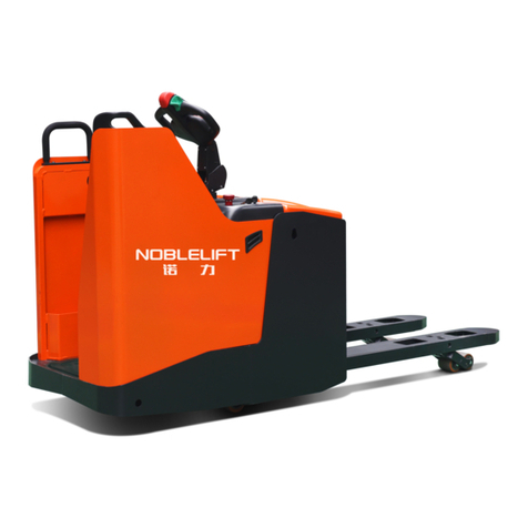
Magliner CooLift CTA43 User manual

1-800-MAGLINE (624-5463) Page 1 www.magliner.com
CooLift®
Serial #: ________________________________
Date of Purchase: ________________________
Service Manual
IMPORTANT: Read entire manual before operating

1-800-MAGLINE (624-5463) Page 2 www.magliner.com
CooLift®
Table of Contents
CooLift Toolkit........................................................................................................................................3
Vertical Loop Handle Removal .............................................................................................................4
Vertical Loop Handle Replacement................................................................................................... 4-5
Bulk Head Removal and Installation.................................................................................................. 6-8
Replacing Foam Handle Sleeve............................................................................................................9
Replacing Corner Post ........................................................................................................................10
Replacing Pallet Stops ........................................................................................................................11
Replacing Vertical Handle Mount Assembly........................................................................................12
Replacing Brushes..............................................................................................................................13
Replacing Front Caster.......................................................................................................................14
Replacing Rear Swivel Caster.............................................................................................................15
Replacing Containment Strap and Tongue..........................................................................................16
Replacing Battery Box.........................................................................................................................17
Changing Battery Cells.................................................................................................................. 18-19
Replacing Deck Positioning (Up/Down) Switch............................................................................. 20-21
Replacing Battery Charger............................................................................................................. 22-24
Replacing Foam Mounting Strips........................................................................................................ 25
Replacing Battery Meter......................................................................................................................26
Replacing Power Switch or Circuit Breaker.........................................................................................27
Changing Wiring Harness.............................................................................................................. 28-29
Changing Axle ............................................................................................................................... 30-31
Changing Brake Caliper ................................................................................................................ 32-33
Changing Brake Pad ..................................................................................................................... 34-35
Changing Upper Brake Line.......................................................................................................... 36-37
Changing Lower Brake Line.......................................................................................................... 38-39
Replacing Brake Master Cylinder.................................................................................................. 40-41
Bleeding Brakes ............................................................................................................................ 42-43
Changing Hydraulic Pump............................................................................................................. 44-45
Changing Hydraulic Cylinder......................................................................................................... 46-47
Bleeding Hydraulic System............................................................................................................ 48-49
Replacing Brake Pawl ................................................................................................................... 50-51
Relocating Master Cylinder .................................................................................................................51
Troubleshooting............................................................................................................................. 52-53
Replacement Parts List ................................................................................................................. 54-56
Inspection / Maintenance Checklist................................................................................................57-63
1-800-MAGLINE (624-5463) Page 3 www.magliner.com
CooLift®
• Set of torx drivers
• #2, #3, #4 Phillips head screwdrivers
• 5/16”, 7/16”, two - 9/16”, 5/8”, 11/16”, 3/4”, 13/16” wrenches
• 6mm, two - 8mm, 10mm, 12mm, 13mm, 14mm, two - 33mm, 35mm
wrenches
• Four spacer blocks (4” x 4” x 24” wooden blocks)
• Isopropyl alcohol
• Vise on workbench
• Four vise-grip plier clamps (size 6r)
• Channel locks
• Rubber mallet
• Drift pin
• 1/2” socket w/extension and ratchet
• Needle nose pliers
• #1 at head screwdriver
• 4mm, 5mm Allen wrench
• 5/16”, 9/64” Allen wrench
• Tape measure
• Torque wrench
• Medium at head screwdriver
• Drip pan (cake pan will work)
• Absorbing material (kitty litter)
• DOT 3 or DOT 4 brake uid
• Hydraulic uid
• Shop towels
• Tube of clear silicone sealant
• Medium strength thread locker
• Flashlight
• Hydraulic thread sealant
• Utility knife
CooLift Toolkit

1-800-MAGLINE (624-5463) Page 4 www.magliner.com
CooLift®
VERTICAL LOOP HANDLE REMOVAL
TOOLS NEEDED:
TORX T30 DRIVER, #3 PHILLIPS SCREWDRIVER 7/16” WRENCH
Note: It is important to keep the CooLift upright at all times.
1) Remove the brake master cylinder using the T30 driver and place it on the top shelf of the user
end cabinet. NOTE: It is not necessary to remove the brake line.
2) Remove the mounting screws (4 upper, 4 lower)(K, I) that connect the vertical loop handles using
#3 Phillips screwdriver and 7/16” wrench. For the CTA48 model, set aside the bulk head mounting
brackets.
3) Remove the two screws (F) that mount the horizontal brace (E) to each of the vertical loop
handles (A, D) using the #3 Phillips screwdriver and the 7/16” wrench.
4) Rotate each of the vertical loop handles (A, D) toward center in order to allow the handles to clear
the upper handle mounts (see illustration for screw locations and handle rotation).
5) The handle assembly consisting of a left and right vertical loop (A, D) and a horizontal brace (E)
should be able to be removed by grasping the entire assembly on both sides at the junction of the
horizontal and vertical components and lifting in an upward motion.
VERTICAL LOOP HANDLE REPLACEMENT
TOOLS NEEDED:
TORX T30 DRIVER, #3 PHILLIPS SCREWDRIVER 7/16” WRENCH
Note: It is important to keep the CooLift upright at all times.
NOTE: Replacing a handle on the CooLift requires that the entire handle assembly rst must be
removed. See Vertical Loop Handle Removal for instructions.
1) With the entire handle assembly removed from the CooLift, slide the vertical loop handle to be
replaced out of the horizontal handle grip mount.
2) Slide the replacement handle into place taking care to minimize scratching or marking on the
aluminum tubing.
3) Grasp each of the vertical loop handles (A, D) by the foam section and rotate the top looped
portion of each section towards the other.
4) Place the base of the handle assembly on top of the cabinet such that the bottom of the vertical
loop handles are located within the arc of the end caps on each of the corner posts and rotate the
top of the vertical loop handles outwardly into position.
5) Place the two screws (K) into holes located within the top section of the vertical loop handles
and then hand tighten it to the frame. For the CTA48 model, be sure to replace the previously
removed bulk head mounting brackets.
6) Place the screws (I) into the holes located in the lower section of the vertical loop handles and
hand tighten them to each of the corner posts.
7) Place the remaining two screws (F) in the holes that secure the horizontal brace (E) to each of the
vertical loop handles (A, D) and tighten them using #3 Phillips screwdriver and 7/16” wrench.
8) Tighten the remaining previously hand tightened screws with #3 Phillips screwdriver and 7/16”
wrench.
9) Position the master cylinder (J) into place on the horizontal brace (E) and tighten the two mounting
screws with the Torx T30 driver.

1-800-MAGLINE (624-5463) Page 5 www.magliner.com
CooLift®
Item Qty. Part Number
A Vertical loop handle - RH 1 309053
B Foam handle sleeve 2 302285
C Steel end cap for vertical loop handle 2 309049
D Vertical loop handle - LH 1 309039
E Horizontal brace 1 309048
F Pan head machine screw - 1/4”-20 x 1-3/4” long 2 80106
G Hex lock nut 1/4”-20 10 80675
H Handle mount bracket 2 302721
I Pan head machine screw - 1/4”-20 x 1-1/2” long 4 80105
J Brake master cylinder 1 309218
KPan head machine screw - 1/4”-20 x 2-1/2” long 4 80108
Pan head machine screw - 1/4”-20 x 3” long (top K screws for
CTA48 model - bottom two K screws are 80108) 280111
A
I
H
G
F
E
D
C
B
J
Rotate loop
handle In toward
center to remove
Rotate loop handle
out to replace
K
K

1-800-MAGLINE (624-5463) Page 6 www.magliner.com
CooLift®
CTA43 BULK HEAD REMOVAL
TOOLS NEEDED:
7/16” WRENCH, 1/2” WRENCH, #3 PHILLIPS SCREWDRIVER, #4 PHILLIPS SCREWDRIVER
SPACER BLOCK (4” x 4” x 24” WOODEN BLOCK)
Note: It is important to keep the CooLift upright at all times.
1) Place the CooLift on a level ooring surface with the holding brake engaged.
2) Raise the deck to the highest position.
3) Place a spacer block between the deck and the base of the cart.
4) Turn off main power switch.
5) Remove the two screws (I) that attach the bulk head (A) to the base plate using the #4 Phillips
screwdriver and the 1/2” wrench.
6) Take out the four screws (G) that attach the bulk head saddle plate (B) and the load retaining strap
assembly and spacer (C, D) to the bulk head and the main cart using the #3 Phillips screwdriver
and the 7/16” wrench.
NOTE: If the bulk head is going to be reinstalled after servicing, only the two screws (G)
anchored to the main cart and the saddle plate need to be removed. If the bulk head is
taken off and the CooLift will be used in the 53” pallet conguration, a new saddle plate
(309151) will need to be installed.
7) Lift and remove the saddle plate. Then lift and remove the bulk head frame to disengage from the
base plate.
CTA43 BULK HEAD INSTALLATION
TOOLS NEEDED:
7/16” WRENCH, 1/2” WRENCH, #3 PHILLIPS SCREWDRIVER, #4 PHILLIPS SCREWDRIVER
SPACER BLOCK (4” x 4” x 24” WOODEN BLOCK)
Note: It is important to keep the CooLift upright at all times.
1) Place the CooLift on a level ooring surface with the holding brake engaged.
2) Raise the deck to the highest position.
3) Insert a spacer block between the deck and the base of the cart.
4) Turn off main power switch.
5) Slide the bulk head (A) into position on the bulk head mounts located on the base plate.
6) Place the bulk head saddle plate (B) into position with the containment strap assembly and strap
spacer (C, D) above it and attach using the four screws (G) and lock nuts (H) and nger tighten.
7) Attach the bulk head to the mounts on the base plate using the two screws (I) and securely tighten
them to the lock nuts (J) using the #4 Phillips screwdriver and the 1/2” wrench.
8) Securely tighten the four screws (G) in the bulk head saddle plate (B) using the #3 Phillips
screwdriver and the 7/16” wrench.

1-800-MAGLINE (624-5463) Page 7 www.magliner.com
CooLift®
Item Qty. for
CTA43 Qty. for
CTA53 Part Number
A Bulk head for CTA43 1 -- 309790
B Bulk head saddle plate for CTA43 1 -- 309341
C Containment strap 1 1 309152
D Containment strap mounting spacer 1 1 309150
E Screw - 3/8”-16 x 1-1/2” long 1 1 79988
F Hex lock nut - 3/8”-16 1 1 80603
G Screw - 1/4”-20 x 2-3/4” long 4 2 80111
H Hex lock nut - 1/4”-20 4 2 80675
I Screw - 5/16”-18 x 1” long 2 -- 80313
J Hex lock nut - 5/16”-18 2 -- 80676
Completed assembly
E
C
D
B
F
G
A
H
J
I

1-800-MAGLINE (624-5463) Page 8 www.magliner.com
CooLift®
CTA48 BULK HEAD REMOVAL
TOOLS NEEDED:
7/16” WRENCH, 1/2” SOCKET END WRENCH, #3 PHILLIPS SCREWDRIVER, TWO 9/16”
WRENCHES, SPACER BLOCK (4” x 4” x 24” WOODEN BLOCK)
Note: It is important to keep the CooLift upright at all times.
1) Place the CooLift on a level ooring surface with the holding brake engaged.
2) Raise the deck to the highest position.
3) Place a spacer block between the deck and the base of the cart.
4) Turn off main power switch.
5) Remove the two screws (I) and lock nuts (F) that attach the bulk head (A) to the base plate using
the 1/2” socket end wrench.
6) Take out the four screws (G) and lock nuts (H) that attach the bulk head saddle plate (B) and the
containment strap assembly and spacer (C, D) to the bulk head and the main cart using the #3
Phillips screwdriver and the 7/16” wrench.
NOTE: If the bulk head is going to be reinstalled after servicing, only the two screws (G)
anchored to the main cart and the saddle plate need to be removed. If the bulk head is
taken off and the CooLift will be used in the 53” pallet conguration, a new saddle plate
(309151) will need to be installed.
7) Lift and remove the saddle plate. Then lift and remove the bulk head frame to disengage from the
base plate.
CTA48 BULK HEAD INSTALLATION
TOOLS NEEDED:
7/16” WRENCH, 1/2” SOCKET END WRENCH, #3 PHILLIPS SCREWDRIVER, TWO 9/16”
WRENCHES, SPACER BLOCK (4” x 4” x 24” WOODEN BLOCK)
Note: It is important to keep the CooLift upright at all times.
1) Place the CooLift on a level ooring surface with the holding brake engaged.
2) Turn off main power switch.
3) Slide the bulk head (A) into position on the base plate in the location shown in Figure 2.
4) Fasten in place using the two screws (I) and lock nuts (F) and nger tighten (the screw heads will
be on top of the base plate and the lock nuts underneath).
5) Place the bulk head saddle plate (B) into position and attach using the four 1/4”-20 x 2-3/4” long
screws (G) and 1/4”-20 lock nuts (H) and nger tighten.
6) Place the containment strap mounting spacer (D) onto the bulk head saddle plate and then place
the containment strap assembly (C) onto the mounting spacer. Insert one 3/8”-16 x 1-1/2” long
screw (E) and 3/8”-16 lock nut (F) and securely tighten using the two 9/16” wrenches.
7) Once all items are in place, securely tighten the hardware for the bulk head saddle plate and for
the hardware connecting the bulk head to the base plate

1-800-MAGLINE (624-5463) Page 9 www.magliner.com
CooLift®
Figure 2
A
B
C
D
GC
F
E
I
H
Item Qty. for
CTA48 Qty. for
CTA53 Part Number
A Bulk head for CTA48 1 -- 309332
B Bulk head saddle plate for CTA48 1 -- 309341
C Containment strap 1 1 309152
D Containment strap mounting spacer 1 1 309150
E Screw - 3/8”-16 x 1-1/2” long 1 1 79988
F Hex lock nut - 3/8”-16 3 1 80603
G Screw - 1/4”-20 x 2-3/4” long 4 2 80111
H Hex lock nut - 1/4”-20 4 2 80675
I Screw - 3/8”-16 x 1-1/4” long 2 -- 80026

1-800-MAGLINE (624-5463) Page 10 www.magliner.com
CooLift®
REPLACING CORNER POST
TOOLS NEEDED:
7/16” WRENCH, 1/2” WRENCH, #3 PHILLIPS HEAD SCREWDRIVER
Note: It is important to keep the CooLift upright at all times.
1) Place the CooLift on a level ooring surface with the holding brake engaged.
2) Turn off main power switch.
3) Remove the battery box (see Replacing Battery Box for proper removal).
4) Remove the ve screws (C, E) and hex nuts (A, D) that connect the corner post to the CooLift using the #3
Phillips head screwdriver and the wrenches and remove the corner post (B).
5) Position the new corner post in place and secure with the previously removed screws and nuts and tighten
with the #3 Phillips head screwdriver and the wrenches.
6) Replace the battery box (see Replacing Battery Box for proper installment).
Item Qty. Part Number
A Hex lock nut - 1/4”-20 3 80675
B Corner post assembly 1 309108
C Screw - 1/4”-20 x 1-1/2” long 3 80105
D Hex lock nut - 5/16”-18 3 80676
E Screw - 5/16”-18 x 1-1/2” long 2 80115
Quantities listed are for one side of the CooLift
B
A
C
E
D
REPLACING FOAM HANDLE SLEEVE
ITEMS NEEDED:
ISOPROPYLALCOHOL
VISE
Note: It is important to keep the CooLift upright at all times.
1) Remove handle (see Vertical Loop Handle Removal for instructions).
2) With the handle assembly off of the cart, slide the vertical loop handle to be replaced out
of the horizontal handle grip mount by moving it upward taking care to manipulate the
orientation in order to minimize scratching or marking on the aluminum tubing.
3) Wipe down the section of the vertical loop handle from the insertion end to the desired
location of the new sleeve with isopropyl alcohol. NOTE: The illustration shows the
sleeve sliding in place from the upper end of the handle but either end is an acceptable
starting point.
4) Saturate the inside of the new sleeve with isopropyl alcohol to allow for a smooth
application to the handle.
5) With the handle held securely in a vise, gradually work the new sleeve into place by
twisting, pulling and sliding, taking care not to rip the foam. Part # 302285

1-800-MAGLINE (624-5463) Page 11 www.magliner.com
CooLift®
B
A
C
B
Figure 1
309206
REPLACING PALLET STOPS - CTA43 AND CTA48
TOOLS NEEDED:
1/2” SOCKET END WRENCH
Note: It is important to keep the CooLift upright at all times.
1) Place the CooLift on a level ooring surface with the holding brake engaged.
2) Turn off main power switch.
3) Remove and discard old pallet stop.
4) Locate the front hole of the pallet stop as shown in Figure 1 and insert the screw (A).
5) Locate the front hole on the deck (for CTA43 models) or the back hole on the deck (for CTA48
models) as shown in Figure 2. Insert the pallet stop (B) and the screw (A) as shown. Fasten
screw with 5/16”-18 lock nut (C) using the 1/2” socket end wrench on the lock nut on the inside of
the deck frame channel.
6) Repeat process for the opposite side. Item Qty. Part Number
A Screw - 5/16”-18 x 1-1/4” long 2 80012
B Pallet stop 1 309206
C Hex lock nut - 5/16”-18 2 80676
Quantities listed are for both sides of the CooLift
Figure 2
CTA48CTA43

1-800-MAGLINE (624-5463) Page 12 www.magliner.com
CooLift®
REPLACING VERTICAL HANDLE MOUNT ASSEMBLY
TOOLS NEEDED:
7/16” WRENCH, 1/2” WRENCH, #3 PHILLIPS SCREWDRIVER
Note: It is important to keep the CooLift upright at all times.
1) Place the CooLift on a level ooring surface with the holding brake engaged.
2) Turn off main power switch.
3) Remove the bulk head (see Bulk Head Removal).
4) Remove vertical loop handles (see Vertical Loop Handle Removal).
5) If you have a CTA48 model, remove the bulk head mount brackets using the #3 Phillips head
screwdriver and the 7/16” wrench.
6) Remove the battery box (see Replacing Battery Box for proper removal).
7) Remove the ten screws - ve on each side - that connect the vertical handle mount assembly to
the CooLift. Use the #3 Phillips head screwdriver and the 7/16” wrench on the top three screws
(B, D) and the #3 Phillips head screwdriver and the 1/2” wrench on the bottom two screws (C) on
each side.
8) Grasp the vertical handle mount assembly (A) to be replaced and lift it straight up to remove it
from the cart.
9) Position the new vertical handle mount assembly (A) into place and secure with the previously
removed screws and nuts and tighten with the #3 Phillips head screwdriver and the 7/16” wrench.
10)Replace the battery box (see Replacing Battery Box instructions for proper installment).
11)Reconnect the handle (see Replacing Vertical Loop Handle).
12)If replacing the assembly on the CTA48 model, reinstall the bulk head mount brackets using the
#3 Phillips head screwdriver and the 7/16” wrench.
13)Reinstall the bulk head (see Installing Bulk Head).
A
B
C
Item Qty Part Number
A Vertical handle mount assembly 1 309087
B Screw - 1/4”-20 x 2-1/2” long 2 80108
C Screw - 5/16”-18 x 1-1/2” long 2 80115
D Screw - 1/4”-20 x 1-1/2” long 1 80105
D
Hardware quantities listed are for one side of the CooLift
CTA48 bulk head
mounting brackets
(2 per side)

1-800-MAGLINE (624-5463) Page 13 www.magliner.com
CooLift®
REPLACING BRUSHES
TOOLS NEEDED:
FLAT HEAD SCREWDRIVER, #3 PHILLIPS SCREWDRIVER, PAIR OF PLIERS
Note: It is important to keep the CooLift upright at all times.
1) Place the CooLift on a level ooring surface.
2) Engage the holding brake.
3) Turn off main power switch.
4) Remove the back access panel from the cart by removing the mounting screws (B) using the #3
Phillips head screwdriver.
5) Insert the at head screwdriver into end of the slotted frame that holds the brush section and bend
the end of the slot open enough to allow the old sections to slide out (A).
6) Remove the old brush sections using the pliers to grab them and slide them out of the slots.
7) Slide in the new brush sections (A) into place.
8) Using the pliers, re-crimp the ends of the slots to enable the brush sections to remain in place.
9) Place the back access panel back into position and secure using the previously removed
mounting screws (B) with the #3 Phillips head screwdriver.
Item Qty Part Number
A Yoke brush 1 309259
BScrew - 1/4”-20 x 3/4” long w/
locking patch 7 80257
B
A

1-800-MAGLINE (624-5463) Page 14 www.magliner.com
CooLift®
REPLACING FRONT CASTER
TOOLS NEEDED:
9/16” WRENCH
TWO 1/2” WRENCHES
Note: It is important to keep the CooLift upright at all times.
Removal
Caution: Remove and replace only one caster at a time.
1) With the cart sitting on a level ooring surface and the holding brake engaged, remove the four
lock nuts (A) that hold the caster yoke (B) to the base of the cart with the 9/16” wrench.
2) The entire front caster assembly can now be lowered and slid out of position.
3) Remove the axle (C) and carriage nut (E) using the two 1/2" wrenches.
4) Remove the four carriage bolts (D) through the bottom of the caster yoke (B).
Replacement
1) With the cart sitting on a level ooring surface and the holding brake engaged, mount the caster
mount to the bottom of the cart using four carriage bolts (D) and tighten with the 9/16” wrench.
2) Position the wheel inside the caster mount, insert the axle (C) and tighten carriage nut (E) using
the two 1/2" wrenches.
A
B
C
D
E
F
Item Qty. Part
Number
AHex lock nut ange - 3/8”-16 4 80624
B Front caster yoke 1 309098
C Axle assembly (includes E) 1 84501
D Carriage bolt - 3/8”-16 x 1” long 4 80127
E Carriage nut (included in 84501) 1 n/a
FCaster wheel - 6” x 2” at tread 1 130014
Quantities listed are for each front caster

1-800-MAGLINE (624-5463) Page 15 www.magliner.com
CooLift®
REPLACING REAR SWIVEL CASTER
TOOLS NEEDED:
TWO 9/16” WRENCHES
Note: It is important to keep the CooLift upright at all times.
Removal
Caution: Remove and replace only one caster at a time.
1) With the cart sitting on a level ooring surface, the holding brake engaged and the rear access
panel removed, loosen the three screws (A,B) that hold the caster mount to the base of the cart
using the pair of 9/16” wrenches.
2) The entire rear swivel caster assembly can now be lowered and slid out of position.
Replacement
1) With the cart sitting on a level ooring surface, the holding brake engaged and the rear access
panel removed, position the replacement rear swivel caster in place and insert the three screws
(A,B) through the base of the cart and the tighten the lock nuts (C) against the swivel caster mount
(D) using the pair of 9/16” wrenches.
2) Replace back access panel.
A
C
D
Item Qty. Part Number
AHex head cap screw - 3/8”-16 x
1-1/4” long 2 80026
BHex head cap screw - 3/8”-16 x
1” long 1 80025
CHex lock nut ange - 3/8”-16 3 80624
DCaster assembly - 6” x 2” swivel
grey at tread 1 130066
Quantities listed are for each rear swivel caster
B

1-800-MAGLINE (624-5463) Page 16 www.magliner.com
CooLift®
REPLACING CONTAINMENT STRAP TONGUE
TOOLS NEEDED: #2 PHILLIPS HEAD SCREWDRIVERAND 3/8” WRENCH
Note: It is important to keep the CooLift upright at all times.
1) Place the CooLift on a level ooring surface with the holding brake engaged.
2) Remove the containment strap tongue (I) by taking out the mounting screw (J) and lock nut (H)
using the #2 Phillips head screwdriver and the 3/8” wrench.
3) Position the new containment strap tongue (J) so the tab with the rectangle-shaped hole is facing
outward from front of cart and the holes are lined up with the holes on the mounting block and
secure it with the previously removed screw (J) and lock nut (H), allowing the tongue to rotate
freely.
REPLACING CONTAINMENT STRAP
TOOLS NEEDED: TWO 1/2” WRENCHES
Note: It is important to keep the CooLift upright at all times.
1) Place the CooLift on a level ooring surface with the holding brake engaged.
2) Remove the containment strap assembly (A) by taking out the mounting screw (C) and lock nut
(D) using the two wrenches.
3) Position the new containment strap assembly (A) such that the tab sits on top of the mounting
spacer (B). Insert the previously removed screw (C) and tighten the lock nut (D) using the two
wrenches.
H
J
I
Front
Underside
View
Item Qty. Part
Number
A Containment strap 1 309152
BContainment strap mounting
spacer 1 309150
C Screw - 3/8”-16 x 1-1/2” long 1 79988
D Hex lock nut - 3/8”-16 1 80603
Item Qty. Part
Number
HHex lock nut w/ nylon insert -
#10-24 UNC 1 80683
I Containment strap tongue 1 309133
J Screw - #10-24 x 2-1/2” long 1 80004
A
B
C
D

1-800-MAGLINE (624-5463) Page 17 www.magliner.com
CooLift®
REPLACING BATTERY BOX
TOOLS NEEDED: #3 PHILLIPS HEAD SCREWDRIVER
Note: It is important to keep the CooLift upright at all times.
1) Place the CooLift on a level ooring surface.
2) Engage the holding brake.
3) Turn off main power switch.
4) Remove the back access panel (B) from the cart by removing the seven mounting screws (A) using the #3
Phillips head screwdriver (Figure 1).
5) Remove the two mounting screws (A) located at the top of the battery box (C) that mounts to the pump
mounting plate using the #3 Phillips head screwdriver (Figure 2).
6) Unplug the charger output cord plug (F) from the battery box (C).
7) Grab the black handle (E) located on the top of the battery box (C) rmly and lift while rotating in a counter
clockwise motion and maneuver the box out of the cabinet.
8) Place the battery box (C) on the oor. Hold the handle (E) rmly with one hand, grasp the red handled loop
connected to the wiring harness (D) with the other hand and pull in an upward motion to disconnect the
battery box (C) from the cart (Figure 3).
9) Position the new battery box (C) on the oor directly behind the CooLift and plug the wiring harness (D)
securely into the tting at the top of the box.
10)Lift the battery box (C) with the handle on the top and maneuver it into position within the cabinet. Plug the
charger output cord (F) into the battery box (C).
11) Secure new battery box (C) with two mounting screws (A) and tighten with the #3 Phillips head screwdriver.
12)Place the back access panel (B) back into position and secure using the seven previously removed
mounting screws (A) with the #3 Phillips head screwdriver.
A
B
A
C
E
D
Figure 2
Figure 1
Figure 3
Item Qty. Part Number
A Screw - 1/4”-20 x 3/4” long w/ locking patch 9 80257
B Back access panel 1 309077
C Battery box assembly 1 309100
D Wiring harness 1 62023
E Battery box handle 1 n/a
F AC charger output cord plug 1 n/a
F

1-800-MAGLINE (624-5463) Page 18 www.magliner.com
CooLift®
CHANGING BATTERY CELLS IN BATTERY BOX
TOOLS NEEDED:
#3 PHILLIPS HEAD SCREWDRIVER
TWO 8mm WRENCHES
1) Remove battery box from CooLift (see Replacing Battery Box), set on workbench and make sure
battery charger is not connected to the charging port.
2) Remove the battery box cover (A) from the battery box assembly (B) by removing the three
mounting screws (C) using the #3 Phillips head screwdriver.
3) Maneuver the defective battery cell(s) (F) such that the terminals can be reached without hitting
the wrench or wrenches on the battery box case which requires shifting forward approximately
1-1/2” inches.
4) Depending upon location of battery cell to be replaced, either a #3 Phillips head screwdriver
and an 8mm wrench or two 8mm wrenches will be needed to remove the wire from the battery
terminals.
5) Regardless of the cell that will be changed it is a good practice to remove the black wire (D) in the
wiring harness connected to the positive terminal on the top battery rst.
6) Remove the wires connecting both terminals of the defective battery using the appropriate
wrenches or screwdriver wrench combination.
7) Slide the defective cell out of the battery box taking care to maneuver over any rubber grommet
(E) and around the wiring.
8) Position the new battery cell (F) in place within the battery box (B) allowing enough room to make
the connections and securely tighten them (see illustration for wiring conguration).
9) Maneuver the newly connected battery into place, position the cover back on the battery box and
secure with the previously removed screws (C) with the #3 Phillips head screwdriver.
A
C
B
Item Qty. Part
Number
A Battery box cover 1 309102
B Battery box assembly (includes batteries) 1 309100
CScrew - pan head screw #8-32 x 1/2” long
with external locking washer 3 80218
D Wiring harness for battery interconnect 1 62024
E Grommet - 5/8” ID x 1-1/8” OD x 3/8” wide 2 309024
F Battery cell - 12v - 18Ah 2 61018
G Wiring harness 1 62023

1-800-MAGLINE (624-5463) Page 19 www.magliner.com
CooLift®
-
+
-
+
+
-
CHARGING PORT
TOP BATTERY
BOTTOM
BATTERY
D
E
F
(top battery cell)
F
(bottom battery cell)
G

1-800-MAGLINE (624-5463) Page 20 www.magliner.com
CooLift®
REPLACING DECK POSITIONING (UP/DOWN) SWITCH
TOOLS NEEDED:
#3 PHILLIPS HEAD SCREWDRIVER, #1 FLAT HEAD SCREWDRIVER, 10mm WRENCH
13mm WRENCH, 5/16” WRENCH, SILICONE SEALANT (CLEAR)
Note: It is important to keep the CooLift upright at all times.
1) Place the CooLift on a level ooring surface.
2) Engage the holding brake.
3) Turn off main power.
4) Remove battery box (see Replacing Battery Box).
5) Remove the jam nut (D) on the cord grip (B) and pull out the rubber insert (E) to allow the cord to
move freely within the tting.
6) Follow the green wire from the up/down switch (A) down in the cabinet where it plugs into a
connector (F) connected to a blue wire and disconnect it by unplugging it.
7) Disconnect the white wire from the switch solenoid (G) using a 10mm wrench.
8) Disconnect the black wire from the switch solenoid (G) using a 13mm wrench.
9) Slide the boot off the white wire that was connected to the switch solenoid (G).
10)Using the #1 screwdriver and the 5/16” wrench remove the nuts off the screws that mount the up/
down switch to the cabinet. NOTE: Do not try to remove the screws entirely from the switch box,
just hold the screws in place and remove the nuts.
11)Feed the disconnected wires through the cabinet via the cord grip (B) and remove the up/down
switch box (A) from the CooLift.
12)Peel off any silicone that is left on the cabinet or the switch box.
13)Place a neoprene washer (H) on each mounting hole and mount the new up/down switch box (A)
on the cabinet using the #1 screwdriver and the 5/16” wrench.
14)Feed the wires through the jam nut (D), the rubber insert (E), and the section of cord grip mounted
on the cabinet and secure by tightening the jam nut (D) by hand.
15)Fasten the white wire on the switch solenoid (G) and secure using the 10mm wrench.
16)Fasten the black wire on the switch solenoid (G) and secure using the 13mm wrench.
17)Connect the green wire terminal to the blue wire terminal (F) that comes from the pump valve coil.
18)Reinstall the battery box (see Replacing Battery Box).
Item Qty. Part
Number
A Operator up/down switch 1 63019
B Cord grip PG-16 (includes D and E) 1 309122
C Hex locknut PG-16 1 309123
D Jam nut 1 n/a
E Rubber insert 1 n/a
F Plug connector 1 n/a
G Solenoid 1 n/a
H Washer, neoprene bonded 2 80730
This manual suits for next models
1
Table of contents
Other Magliner Truck manuals

Magliner
Magliner GEMINI Sr. User manual

Magliner
Magliner 170 Ergo User manual

Magliner
Magliner HRK User manual

Magliner
Magliner 111-AA-815 User manual

Magliner
Magliner C5 User manual

Magliner
Magliner Y-Cable User manual

Magliner
Magliner GEMINI XL User manual

Magliner
Magliner MTA2-L User manual

Magliner
Magliner MAG220 User manual

Magliner
Magliner C5 User manual