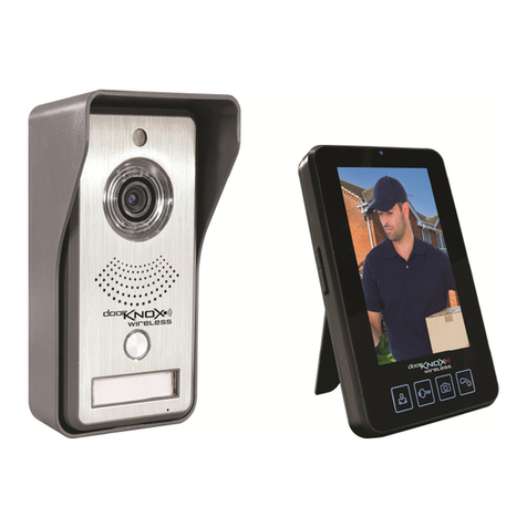
Door Knox XVDP500 User manual

Doc XVDP500
Door Entry System - Door Knox
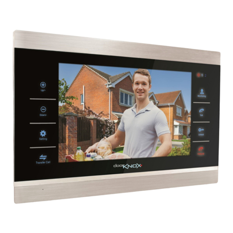
The Door Knox entry system has a 7” touch screen with hands free intercom.
The VDP500 Door Knox colour video door phone system can be used to control an electronic door
loc or electrically operated outdoor gate as well as providing a hands free intercom facility with
colour video 7” LCD display with tal bac facility. The system can be extended for up to four
indoor monitor displays and two outdoor door cameras.
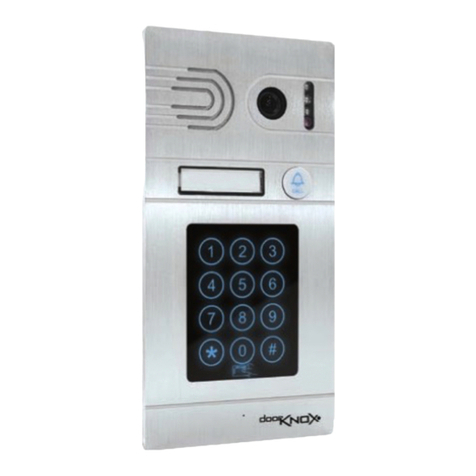
The outdoor camera unit has a control button, for audio and video display on the internal monitor
but the internal monitor can also be used to view the camera/s by pressing the view button/s.
The internal monitor with video and audio will switch off after one minute automatically. It has
control switches for playing sixteen different melodies with volume control adjustment, brightness
and contrast for video display and volume control for tal bac .
VDP500 Door Knox Camera & Monitor Kit Contents
The VDP500 consists of the following components:
1 x 7” Colour Door Knox Monitor with securing bac plate VDP200
1 x Door Knox Camera Unit, mounting brac et and screws VDP100
2 x Fly Leads for connecting cameras (note one spare for connecting additional camera)
1 x White 4 core Extension Cable approximately 14 metres
1 x 12vDC 1.1A power supply unit
Email: [email protected] Last Revised: 07/10/2015

Doc XVDP500
Door Entry System - Door Knox
afety Instructions
1. Ensure that the indoor monitor is not subject to high temperature or high humidity and must
not subject to direct sunlight.
2. The indoor monitor must not be installed close to a television as this may cause interference.
3. The indoor monitor should not be handled with wet hands.
4. Clean the indoor monitor and camera with a soft cloth and do not use liquids or solvents.
5. Ensure that the equipment is not subject to shoc .
6. It is recommended to not point the camera at direct sunlight as this may affect picture
quality.
7. To prevent damage the indoor monitor should be fastened to a wall.
8. Always use a 12vDC >1.1A regulated power supply.
Installation Instructions
Email: [email protected] Last Revised: 07/10/2015
Connecting Indoor Monitor
1. Connect a fly lead to B.
2. Connect wires to white
extension cable using a terminal
connector (not supplied) noting
cables used for audio, ground,
power and video.
3. Connect power supply to A but
do not power up yet.
4. If you are installing a second
camera connect second fly lead
to C and follow step 2.
A
B
C
Audio Ground VCC Video
12v DC

Doc XVDP500
Door Entry System - Door Knox
5. Fit the monitor bac plate to the wall
as shown on the right. The monitor
can now be clipped onto the bac plate.
Connecting Camera Unit
6. Fit the camera brac et to a post
or wall. This provides protection
from the weather.
Email: [email protected] Last Revised: 07/10/2015
7. Connect the white extension cable to the camera
ensuring the wires are connected as
shown. Press grey square above wire entry to
enter cable.
8. Note that Connection 1 is Audio
Connection 2 is Ground
Connection 3 is Video
Connection 4 is VCC 12v DC
Be aware that connections for video and 12vDC
are reversed on monitor.
9. Connect Electronic Loc to 5 and 6. Note that
a zero volt switch is momentarily activated when
pressing the unloc button. If you have a voltage
controlled solenoid and/or require a latching
connection, you will have to use an appropriate
interface.
audio ground video VCC 12vDC
Fixing holes
Warning!
The order of the coloured wires may
differ to those in the picture. Ensure
you wire according to the text.

Doc XVDP500
Door Entry System - Door Knox
The white 4 core extension cable is approximately 14 metres long. If you need a longer run please
note that to avoid voltage drop, you will need to use a heavier cable size as follows:
≤ 28 metre cable core size ≥ 0.2mm2
≤ 50 metre cable core size ≥ 0.3mm2
≤ 70 metre cable core size ≥ 0.5mm2
Email: [email protected] Last Revised: 07/10/2015
11. Connect the camera to the camera brac et by
removing the blac rubber plug, securing with
screws provided and replacing blac rubber
plugs to ensure weatherproof.
12. Power up system.
Additional Cameras and/or indoor Monitors
You can install one camera with 1 ~ 4 monitors
or two cameras with 1 ~ 4 monitors. The examples
below show how these are wired.
1 camera unit with 1 ~ 4 monitors
2 camera units with 1 ~ 4 monitors

Doc XVDP500
Door Entry System - Door Knox
Operating Instructions
1.Outdoor Camera
When a visitor presses the CALL button on the outdoor camera unit, a melody will be played on the
indoor monitor and a picture will be displayed.
If the CALL button is pressed again and the monitor is still on, the melody will play again but the
monitor will close down after one minute if nobody answers from the monitor.
3.
4.Indoor Monitor Controls
a. Volume Control
b. Contrast Control
c. Brightness Control
d. Melody selection 16 different melodies
e. Melody Volume (L / M / H) Low, Medium or High volume.
Email: [email protected] Last Revised: 07/10/2015
TALK BUTTON
Press the TALK (phone) button on one of the
monitors ensuring all monitors are in Monitor
mode.
Press the TALK button again to end. The call
will last for one minute. The call will
automatically close down after one minute if
not answered.
UNLOCK BUTTON
2. Unlock Door or Gate
When visitor calls from the outdoor camera unit,
press the UNLOCK button or you can
press whilst tal ing to your visitor. The door/gate
will be unloc ed. Although opened the system is
still on and will turn off automatically after one
minute, unless you press the TALK button to
close communication immediately.
CAMERA 2
3. Indoor Monitor
Press either CAMERA 1 or CAMERA 2 button
and the camera will display the outside picture.
Press the same button to close. The monitoring
time is one minute. The door and gate can be
unloc ed and you can also press the TALK
button. Again press this button to close or wait
one minute.
CAMERA 1
a. b. c. d. e.

Doc XVDP500
Door Entry System - Door Knox
Technical pecifications
Voltage 12v DC
Current
tandby Mode 40mA
Operating 400mA
Working Distance
≤ 28 metres core size ≥ 0.2mm2
≤ 50 metres core size ≥ 0.3mm2
≤ 70 metres core size ≥ 0.5mm2
Power upply 12v DC 1.1A
Unlock Function Provides non latching zero volt switch
5A normally open Relay contact
Intercom Type Hands free 2 way intercom
Working Temperature
-10°C ~ +50°C Indoor Monitor
-10°C ~ +50°C Outdoor Monitor
Email: [email protected] Last Revised: 07/10/2015
This symbol on the products and/or accompanying documents means
that used electronic equipment must not be mixed with general
household waste. For treatment, recovery and recycling please return
this unit to your trade supplier or local designated collection point as
defined by your local council.
WEE/ G0783SS
All specifications are approximate. doorknox.com reserves the
right to change any product specifications or features without
notice. Whilst every effort is made to ensure that these
instructions are complete and accurate, doorknox.com cannot
be held responsible in any way for any losses, no matter how
they arise, from errors or omissions in these instructions, or
the performance or non-performance of the equipment that
these instructions refer to.
Table of contents
Other Door Knox Intercom System manuals