Door Knox VDP102 User manual

XVDP-01
•Professional Door Entry Systems •

Find out more at www.DoorKnox.com2
Introduction
The DoorKnox range of high spec equipment can
be combined to create a comprehensive video
door entry system for any environment. From a
small residential project with a single camera and
a modest 4” monitor to multiple cameras with key
code and key fob entry displayed on multiple 10”
monitors for a large commercial site.
Each external door camera has its own distinctive
style to suit the taste of the customer and the
environment it is being installed into. They all
feature a high resolution 800TVL camera, two way
audio and IR LEDs so you can still see who’s calling
on the darkest of nights.
Our touch button monitors provide you with full
control of your door entry system and are available
in a choice of three sizes; 4”, 7” and 10”. Two door
cameras and two door locks can be connected to
the monitor as well as two analogue CCTV cameras
with alarms for intruder detection.
For added security and peace of mind all of our
monitors have a clever feature which captures a
snapshot whenever the door camera is pressed
and saves it into the built in internal storage. The
storage capacity can be extended with the 32GB
memory card supplied with the monitor. There’s
also video output for connecting to a DVR for a
fully integrated security system.
With the feature packed DoorKnox range you
can create a complete, versatile video door entry
solution which out performs any other.

Find out more at www.DoorKnox.com 3
Contents
Commonly Asked Questions 04
VDP101 - Traditional Door Entry Camera 06
VDP102 - Wide Angle Door Entry Camera 08
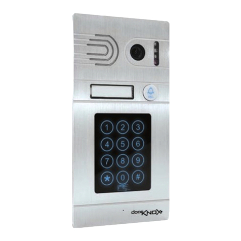
VDP103 - Secure Access Door Entry Camera 10
Door Entry Monitors 14
Wiring A System 19
Connections 19
Powering & Cabling 20
System Overview 21
Door Cameras To Door Monitors 22
Auxiliary Cameras & Alarms 23
Connecting A System To An Alien DVR 24
Connecting A Camera To An Alien DVR 25
Recording On An Alien DVR 28
Using The Menu System 33
Using Your Door Entry System 42
Fault Finding 44
Other Products To Consider 45

Find out more at www.DoorKnox.com4
Commonly Asked Questions
Q. What does the DoorKnox do?
In its basic format it consists of 1 monitor located
inside a property and a camera with a “Call button” on
the outside of the property. When someone presses
the Call button it chimes the monitor and the person
inside can see the visitor. A two way intercom allows
the occupier to chat to the visitor and then remotely
operate a door release to let the visitor in.
Q. Does the DoorKnox record the visitor if I’m out, so I
can see who’s been? How do I view the images?
Yes it does. It can record a small amount of video
(2mins) or around 80 images on an SD card inside the
monitor. You can play them on the monitor or you
could take the micro-SD card out and play it on a PC.
Q. If I’m not at home can the DoorKnox remotely notify
me if someone is at my property?
Yes it can! To do this you need to link the DoorKnox to
the “AlienDVR”. The DoorKnox's Call button and video
output are connected to the DVR. When someone
presses the Call button on the DoorKnox camera it
“alarms” the DVR. The DVR records the visitor and
can email you three snap shots from the camera to
your phone! You could then log into the DVR via the
AlienDVR app and see and hear live video and audio!
Q. Wow. Could I remotely open a door using my phone?
Yes using the AlienDVR phone app and its relay
controls to open the door. You will need to t a
suitable electromechanical lock to the door as well.
Q. So one of the real benets of the DoorKnox is you
can link it to the AlienDVR?
Yes, it’s the number one feature, making it a really
comprehensive system. Most low cost Video door
phones don’t have this system integration.
Q. Can I see the DVR's output on the DoorKnox screen?
Yes! The DoorKnox monitor can accept two additional
composite video inputs from additional standard
CCTV cameras or a DVR's video output. If the DVR
doesn’t have a composite video output you can create
one with a composite convertor like the CNV100.
Q. So that means I could play the DVR through the
DoorKnox and watch footage on the DoorKnox screen?
Yes you would simply select the auxiliary video on the

Find out more at www.DoorKnox.com 5
Commonly Asked Questions
DoorKnox monitor and you would be able to see the
DVR output. The DoorKnox doesn’t control the DVR so
you would still need the DVR's remote control.
Q. Can I use the DoorKnox to win sales from?
Sure, you can sell it as a new system OR integrated
to an old system! Go around your customers and tell
them it’s a new add on to the AlienDVR!
Q. What other features could be useful to me?
You could add a DoorKnox camera to the DVR directly to
get a really low cost CCTV camera that’s also a “doorbell”.
Q. So I can wire a DoorKnox camera to the DVR?
Yes you can! It’s the perfect solution for cameras in
entrances and door ways to get a great mug shot of
your visitors! The camera just needs 12V power and
has a video output that the AlienDVR will see and
record straight away.
Q. It is amazing! Can the DVR record sound from the
cameras alone if I don’t have a monitor?
Yes it can but you need a few simple additional
components to do that which System Q can supply.
Q. So if I just have the camera can I use the Call button
to directly trigger the DVR as well, again without the
DoorKnox monitor?
Indeed!! Again you need the additional components.
Q. Can you get all these features with the DoorKnox on
other DVRs than the Alien?
No. Some features like the video may work on other
DVR’s (if it’s a multi technology input) but it’s unlikely
audio or alarms will work, you need to use the Alien.
Q. Can you use DoorKnox as an access control point
with a key pad or entry card?
Yes! We do an external camera unit with both those
features! This allows yourself, sta or residents an easy
and simple way to enter and unlock a door or a gate.
Q. Is it easy to t?
Very easy. A basic system uses a four core cable
between the camera and monitor so it’s a doddle.
Q. If I don’t have the DoorKnox monitor can I talk directly
back to a DoorKnox camera from the DVR?
Not yet but we are working on it!

Find out more at www.DoorKnox.com6
VDP101 - Traditional Door Entry Camera
Image Sensor 1/3” CMOS
Resolution 800TVL
Lens Type 3.7mm Pinhole / 68º Viewing Angle
Power 12V DC / ≤200mA
Build Rust-proof aluminium alloy
Dimensions (H) 123.5 x (W) 44.5 x (D) 50mm (Including Shield)
The stone eect and classic
design of the VDP101
makes it a rm favourite for
installs on more traditional
properties.
The camera is supplied
with an optional sun/rain
shield and angled bracket
to help you capture the
best possible images.
There’s also a matching
recessed mount bracket
available for a smarter
looking nish.
Order code
VDP101-BASE
(
See pg 48
).
Features & Connections
3.7mm Pinhole
lens
Microphone
IR LEDs and
photocell
Call button
Mounting
hole
Mounting
hole
Concealed
speaker

Find out more at www.DoorKnox.com 7
VDP101 - Traditional Door Entry Camera
Mounting
When mounting the door entry camera we recommend
that it is installed between 150 to 160cm above the oor
(About 5 feet) and where it will not be in direct sunlight.
VDP101-BASE
recess mount also
available (pg 48).
Recess required
129 x 46 x 17mm
A
Countersunk
cross-head
B
Pan head
cross-head
+12V DC (Red)
Audio (White)
GND (Black)
Video (Yellow)
NO (Green)
NC (Brown)
COM (Orange)
Speaker Volume
Control
Surface Mounting
Recessed Mounting
Angle Mounting
A
A
AA
A
BB
B
B
A
For more information on wiring a system see pages 19-27.

Find out more at www.DoorKnox.com8
VDP102 - Wide Angle Door Entry Camera
Image Sensor 1/3” CMOS
Resolution 800TVL
Lens Type 2.4mm Wide Angle Pinhole / 110º Viewing Angle
Power 12V DC / ≤200mA
Build Rust-proof aluminium alloy
Dimensions (H) 128 x (W) 49 x (D) 41mm
With its sleek and
contemporary design the
VDP102 looks great on
modern residential, retail
and commercial installs.
The wide angle 2.4mm
lens allows you to see
more giving you a better
idea as to who’s calling.
The VDP102 features a
built-in sun/rain shield
and is supplied with an
optional angled bracket
so that you can attain the
perfect image.
Features & Connections
2.4mm wide
angle lens
Microphone
IR LEDs and
photocell
Call button
Concealed
speaker

Find out more at www.DoorKnox.com 9
VDP102 - Wide Angle Door Entry Camera
+12V DC (Red)
Audio (White)
GND (Black)
Video (Yellow)
NO (Green)
NC (Brown)
COM (Orange)
Speaker Volume
Control
Mounting
When mounting the door entry camera we recommend
that it is installed between 150 to 160cm above the oor
(About 5 feet) and where it will not be in direct sunlight.
Surface Mounting
Angle
Mounting
A
B
AB
B
A
For more information on wiring a system see pages 19-27.

Find out more at www.DoorKnox.com10
VDP103 - Secure Access Door Entry Camera
Image Sensor 1/3” CMOS
Resolution 800TVL
Lens Type 3.6mm Board / 85º Viewing Angle
Power 12V DC / ≤300mA
Build Rust-proof aluminium alloy
Dimensions (H) 210 x (W) 105 x (D) 32mm
With a stylish brushed
aluminium nish and quality
build the VDP103 is ideal for
retail and commercial projects.
As well as functioning as a
standard door entry camera,
trusted users can also gain
entrance to the building using
the VDP103 with either a key
card, programmable key code
or key fob (2 key fobs supplied).
Use a combination of up to
40 key fobs and key cards.
Order Code Fob VDPFOB01
Order Code Card VDPCARD01
Features & Connections
3.6mm lens
Microphone
IR LEDs and
photocell
Call button
Speaker
Name plate
(Push down
on either side
to remove)
Keypad &
key fob sensor

Find out more at www.DoorKnox.com 11
VDP103 - Secure Access Door Entry Camera
Mounting
When mounting the door entry camera we recommend
that it is installed between 150 to 160cm above the oor
(About 5 feet) and where it will not be in direct sunlight.
If you choose to recess mount the camera you will need
to create a recess of 200mm (h) x 96mm (w) x 29mm (d).
It is important that the recess created is no more than
30mm deep as you will not be able to secure the camera.
+12V DC (Red)
Audio (White)
GND (Black)
Video (Yellow)
NO (Green)
NC (Brown)
COM (Orange)
Speaker Volume
Control
‘ENTER’ button
‘ESC’ button
For more information on wiring a system see pages 19-27.

Find out more at www.DoorKnox.com12
VDP103 - Secure Access Door Entry Camera
Creating New Key Codes
Up to 40 key codes can be saved to each VDP103 door
camera. Creating new key codes is easy as described
in the steps below:
1Press ‘
ENTER
’ on the rear of the camera and you
will hear a beep.
2Enter your new key code followed by the ‘
#
’ key.
You will hear a long beep conrming the new
key code has been created.
Note Key codes must be between 4 and 8 characters
long and can not include the ‘*’ or ‘#’ key.
If the maximum 8 characters are entered you
will hear a long beep conrming the key code
has been created so you don’t need to press
the ‘
#
’ key.
Pairing Key Fobs & Key Cards
A combination of up to 40 key fobs and cards can be
paired to a single VDP103. Each key fob/card however
can be paired to multiple door cameras so the same
key fob/card can be used to open multiple doors.
You will need to pair the key fob/card to each door
entry unit separately. To pair a key fob/card to a
VDP103 just follow the simple steps below:
1Press ‘
ENTER
’ on the rear of the camera and you
will hear a beep.
2Swipe the key fob across the keypad. You will hear
a long beep conrming the key fob had been
paired successfully.
www.DoorKnox.com
Swipe the key fob across the keypad. You will hear
a long beep conrming the key fob had been
paired successfully.

Find out more at www.DoorKnox.com 13
VDP103 - Secure Access Door Entry Camera
Deleting Users
To improve security form time to time you may wish
to change key codes and unpair key fobs or key cards.
To restore the VDP103 back to factory default deleting
all users just follow the steps below:
1Press and hold the ‘
ENTER
’ and ‘
ESC
’ buttons
on the rear of the camera at the same time for
10 seconds.
2
After 10 seconds you will hear a long beep
conrming all users have been erased. You can
now follow the easy steps on the previous page
to create new key codes and pair required
key fobs and cards.
Entering Key codes
To release an electronic
door using a key code
simply enter the key code
followed by the ‘#’ key (No
need to press‘#’for 8 digit
key codes). You will hear a
long beep if the key code
is correct. If incorrect you
will hear two short beeps.
Using A Key fob/Card
To release an electronic
door with a paired key fob
or key card just swipe it
across the keypad and you
will hear a long beep. Two
short beeps indicate the
key fob/card is not paired
with the door camera.
Using The VDP103 Door Camera

Find out more at www.DoorKnox.com14
Door Entry Monitors - Specications
VDP204 VDP207 VDP210
Screen Size 4” 7” 10.1”
Resolution 320 x 240 800 x 600 1024 x 600
Camera Inputs 2x Door Cameras / 2x Auxiliary Cameras 2x Door Cameras / 2x Auxiliary Cameras 2x Door Cameras / 2x Auxiliary Cameras
Door Monitor Inputs 1 1 1
Door Monitor Outputs 1 (3 Slaves Max) 1 (3 Slaves Max) 1 (3 Slaves Max)
TV Monitor Outputs 1 (720 x 576) 1 (720 x 576) 1 (720 x 576)
Memory Card Slot Micro SD / 32GB Max / Class 10 Min
(Supplied)
Micro SD / 32GB Max / Class 10 Min
(Supplied) SD / 32GB Max / Class 10 Min (Supplied)
Power / Consumption 12V DC / 300mA (1A PSU Supplied) 12V DC / 400mA (1A PSU Supplied) 12V DC / 500mA (1A PSU Supplied)
12V DC Output 400mA Max Across All Outputs 400mA Max Across All Outputs 400mA Max Across All Outputs
Build Plastic (Brushed Aluminium Eect) Brushed Aluminium & Plastic Brushed Aluminium & Plastic
Dimensions (H) 169 x (W) 119 x (D) 21mm (H) 165 x (W) 245 x (D) 23mm (H) 210 x (W) 334 x (D) 27mm
Each of our quality touch button
door monitors can be connected to
two door cameras plus two auxiliary
cameras. Up to four door monitors
can be connected together and
there’s even a TV monitor output so
your door entry system can be fully
integrated into your CCTV system.
VDP204
VDP210
VDP207

Find out more at www.DoorKnox.com 15
Door Entry Monitors - VDP204 Features
1 Power Indicator
2 Door camera indicator shows which camera is being displayed
3 Transfer - Send call to other monitor(s) / Intercom
4 Monitoring - Switch between camera inputs
5 Unlock - Unlock door connected to camera being displayed
6
Answer Intercom - Answer call / End call / Return in menu system
7 Microphone
8 Settings - Press to enter menu system / Flick up and down to
navigate menu system / Press again to make selection
9 Volume control
10 Micro SD card slot
3
1
68
9
10
7
4
2
5

Find out more at www.DoorKnox.com16
Door Entry Monitors - VDP207 Features
1 Power Indicator
2 Door camera indicator shows which camera is being displayed
3 Up - Volume up / Move up in menu system
4 Down - Volume down / Move down in menu system
5 Transfer - Send call to other monitor(s) / Intercom
6 Settings - Enter menu system / Press again to make selection
7 Talk - Answer call
8 Monitoring - Switch between camera inputs
9 Hang Up - End call
/ Return to previous screen / Cancel
10 Unlock - Unlock door connected to camera being displayed
11 Microphone
12 Micro SD card slot
3
2
1
4
56
78
9
11
12
10

Find out more at www.DoorKnox.com 17
Door Entry Monitors - VDP210 Features
1 Power Indicator
2 Door camera indicator shows which camera is being displayed
3 Up - Volume up / Move up in menu system
4 Down - Volume down / Move down in menu system
5 Settings - Enter menu system / Press again to make selection
6 Transfer - Send call to other monitor(s) / Intercom
7 Monitoring - Switch between camera inputs
8 Talk - Answer call
9 Unlock - Unlock door connected to camera being displayed
10 Hang Up - End call
/ Return to previous screen / Cancel
11 Microphone
12 SD card slot
7
2
3
8
4
9
5
10
12
6
11
1

Find out more at www.DoorKnox.com18
Door Entry Monitors - Mounting & Connections
Connections
To make life easier all three monitors feature the exact
same connection layout as shown below.
Mounting
The principles are the same for mounting each
monitor. The mounting plate is secured to the
mounting surface and then the monitor simply slots
on to it. There is a large hole in the centre of the
mounting plate to allow the cables to pass through.
TV Out Power
Door Cam 1 Auxiliary Cam 1 Monitor In
Door Cam 2 Auxiliary Cam 2 Monitor Out
GND GND
Video +12V
+12V +12V Audio
+12V +12V Audio
Audio Alarm GND
GND GND Data
Video Video Video
Audio Alarm GND
GND GND Data
Video Video Video
VDP204 & VDP207
VDP210
Click!

Find out more at www.DoorKnox.com 19
Wiring A System - Connections
Cameras
All of our door cameras have connection cables
terminated into the same 7 colour coordinated wires.
4 wires are used to connect to the monitor and then
2 of the 3 remaining wires are used to connect to an
electronic door lock. The common (COM) wire is always
used along with either the normally open (NO) or
normally closed (NC) wire depending on the lock type.
Monitors
Every monitor is supplied with 5x 4 wire y-leads and
1x 2 wire y-lead.
The 4 wire y-leads are terminated into 4 pin plugs
which are simply inserted into the sockets on the
rear of the monitor. These are used for connecting
door cameras, auxiliary cameras and additional door
monitors as shown on the previous page. To make
installation easier the 4 wires are colour co-ordinated
to match the 4 wires from the door camera.
The two wire y-lead is terminated with a 2 pin plug
and is used as the TV out for connecting the door
monitor to a TV monitor or DVR.
+12V DC (Red)
Audio (White)
Ground (Black)
Video (Yellow)
NO (Green)
COM (Orange)
NC (Brown)
From
Camera
To
Monitor
To
Door Lock
x5
x1

Find out more at www.DoorKnox.com20
Wiring A System - Powering & Cabling
Powering Cameras
Door cameras and auxiliary cameras can be powered
in two ways, either locally or via the door monitor.
The DoorKnox monitors can supply a 12V DC output
to any of the four cameras but can only supply a
maximum of 400mA across all outputs. To power a
camera using a door monitor simply connect the wires
as shown on page 22.
To power a camera locally connect the Audio (white)
and Video (yellow) to the door monitor, the GND
(black) to the PSU
and
the door monitor and then the
12V DC (red) to the PSU only.
Powering Monitors
Door monitors are
supplied with a 12V DC
1A plug-in PSU that
terminates into a 2 pin
plug which slots into
the rear of the monitor.
See page 18
.
Cable Runs
The maximum achievable cable run is limited by the
voltage drop in the chosen cable. Resistance diers
depending on the cable used and the higher the
resistance the more dramatic the voltage drop.
We recommend that you use one of three types of
cable, PTZ combo cable sometimes known as RG59+4,
CAT5+2 cable or 4 core cable with 0.3mm
2
cores.
The table below shows the maximum recommended
cable run for each cable type. Cable runs exceeding
the stated maximum run are at risk of issues caused by
voltage drop and non performance of equipment.
Cable Type Max Cable Run
PTZ Combo Cable (RG59+4) Up To 150m
CAT5+2 Up To 100m
4 Core Cable (0.3mm2)Up To 50m
Note
Distances stated are based on a monitor powering
two door cameras and no auxiliary cameras.
This manual suits for next models
5
Table of contents
Other Door Knox Intercom System manuals
Popular Intercom System manuals by other brands

ACO
ACO CDNP7ACC Extended user manual

Comelit
Comelit 3460EA Technical manual

urmet domus
urmet domus mikra2 1060/21 INSTALLATION AND USE BOOKLET

AES global
AES global Praetorian Guard Series Installation & user's instructions

XONTEL
XONTEL XT-11P user manual

Chamberlain
Chamberlain myQ Business CAPXM installation manual