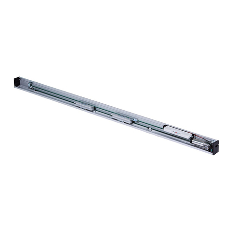
Doortec DOORMAN SDO1 Operating instructions

!
SD-03
WARNING: IT IS VITAL FOR THE SAFETY OF ALL PERSONS INSTALLING AND USING THIS OPENER TO FOLLOW
THE INSTALLATION INSTRUCTIONS AND SAFETY WARNINGS. FAILURE TO COMPLY MAY RESULT IN SERIOUS
PERSONAL INJURY AND/OR PROPERTY DAMAGE AND DAMAGE TO THE OPENER AND DOOR
INSTALLATION & OWNERS MANUAL

1. One year manufacturer’s Warrantee
The DOORMAN opener carries a 12 month factory warrantee from date of invoice.
Faulty openers will be repaired or replaced by the sole discretion of AUTOMATION AFRICA.
The labour costs involved for replacement or repairs will be for the customers account and is not
covered by this warrantee.
The transport to and from AUTOMATION AFRICA of items is for the customer’s account.
All warrantee claims must be accompanied by the original invoice.
The warrantee does not cover non-defect damage caused by unreasonable use or wrongly installed
components.
This warrantee excludes lightening damage, insect damage, water damage, acts of God and improper
installation.
This warrantee excludes remote controls, bulbs and back up batteries.
The following conditions will disqualify this product from
warrantee as laid out above
Any DOORMAN opener used to automate more than one door at a time.
Any DOORMAN opener used outdoors, including carports.
Any Doorman opener used in excessive traffic applications such as multi apartment parking garages.
When any DOORMAN opener is not installed by a QUALIFIED installer.
Any unauthorized non-manufacturer modifications to the opener or components thereof.

2.Technical Specifications
3.Installation
3.1 Recommended Tools
!
2
Power Input
220VAC±10% 50~60Hz
Reception
frequency
433.92MH
Motor
24VDC
Decoding
Rolling Code
Working
Temperature
>-20~50℃
Transmitter
power
27A 12V Battery
Relative Humidity
≦90%
Globe
24V 5W
Open and close force
800N
Courtesy light
time
3 minutes

3.2 Installing the Operator and Rail
3
Optional For Steel Rail

4.Control panel
5.Optional Terminals and Connections
4
Photo beam

6.Programming the Operator
6.1
Preparation
!
6.1.1
Keep trolley locked, pull and/or push the door by hand, make
sure the trolley connects with the traveller.
6.1.2
Turn on the power, the courtesy light is on for several seconds,
the LED displays the numbers from “ 9 ” to “ 1 ”.
The operator turns to standby mode.
6.1.3
After the units “self-testing” it displays “ II ” or “ -”.
6.2
Setting Open and Close Limits
6.2.1
Press and hold SET until the unit displays “ 1”.
6.2.2
Press and hold UP, for opening limit, the door will start to
run
6.2.3
When the door has reached the open position, press SET
to confirm setting. The unit displays “ 2”.
6.2.4
Press and hold DOWN, for close limit. When the door has
reached the closed position, press SET to confirm setting.
6.2.5
The door will now open and close automatically to map
the open and close sensitivity force requirements.
6.2.6
The unit displays “ II ” to show the setting is complete.
6.3
Self Learning Transmitter
!
6.3.1
When the unit has stored 20 codes, it will flash “ F ”, This
indicates that the receiver has reached its limit and is full.
6.3.2
Press and hold CODE, until it displays “ ”.
6.3.3
Hold for more than 8 seconds, until the unit flashes “ C`” ,
all remotes are now deleted.
6.4
Adding or Changing Transmitters
6.4.1
Press and release CODE, the unit displays “ ”.
6.4.2
Press a button on the transmitter, then release and press
the same button again, “ ” flashes,
6.4.3
The unit displays “ II ” to show setting is complete. Repeat
above steps to code a maximum of 20 different
transmitters.
5

6.5
Force Adjustments
6.5.1
Press and hold SET, the unit displays “ 3 ”.
6.5.2
Press SET once again, it will show the current setting.
Press UP to increase the force by one degree or press
DOWN to decrease by one degree. Maximum degree is
“ 9”, minimum is “ 1 ”.
6.5.3
Press SET to confirm. The default setting is “ 5”.
6.5.4
After finishing all the settings, please check the force to
make sure of settings.
6.6
Holiday Lockout – not recommended
6.6.1
Press and hold SET, the unit displays “ 4”.
6.6.2
Press SET to show current setting. Press UP, it displays
“ 1”, lockout function enabled or press DOWN, It displays
“ 0”, lockout function disabled. Press SET to confirm the
function you require.
6.6.3
When using uncovered transmitters, it is recommended
using the lockout function. This function works when the
door reaches the closed position, you can’t open the door
until “lockout” has been disabled first.
6.7
Photo Beam
6.7.1
Press and hold DOWN, the unit displays “ - ” .
6.7.2
Press SET to show current setting. Press UP once the
unit displays “ H”, the photo beam is enabled. Press
down once, the unit displays “ II ”, the photo beam is
disabled. Press SET to confirm required setting and quit.
6.7.3
If you do not make use of the photo beam device,
please make sure it displays “ II ” , to disable this
function.
6.8
Auto-Close ON/OFF
6.8.1
Press and hold UP, the unit displays “ - ”.
6.8.2
Press SET to show current setting. Press UP to increase
the auto-close time by one minute or press DOWN to
decrease by one minute. Maximum time is “ 9 ” , minimum
is “ 0 ”. Press SET to confirm.
6.8.3
The default setting is “ 0 ”, “ 0 ” shows auto-
close off. This function works when the door
reaches the fully open position.
6

7.Owners’ Guide
7.1
Attention
7.1.1
At the first time of using the door, please test the driving
system to see if it moves smoothly. (Test method: unlock
the traveller, pull and push the door by hand.)
7.1.2
Connect to appropriate power socket with earth
7.1.3
Use the transmitters only while the door is in sight. Do not
stand or walk under a moving door. The transmitters should
be out of reach of children.
7.1.4
Make sure the opener is not used in very hot places above
50 deg. Celsius, Very damp or moist places
7.1.5
Check at least twice a year to make sure the door is
properly balanced and that all working parts are in good
working condition. Adjust the tension of chain. Add suitable
amount of lubrication to the chain system.
7.2
Trouble-Shooting Guide
7.2.1
Problem
Causes
Solution
7.2.2
The chain is noisy.
The chain is too loose.
Adjust nut-M8 referring
to 3.2.C.
7.2.3
The motor does not
open or close.
No limits set
Check limit settings.
7.2.4
After setting open
and close positions,
the motor does not
work.
The screws of the Hall
encoder are loose or
hall encoder is faulty.
Tighten the screws or
replace the hall
encoder.
7.2.5
The motor does not
close.
Photo beam function
is enabled.
Cancel the photo beam
function, refer to 6.7.
7.2.6
The wall button
works, but the
transmitter doesn’t
work.
Transmitter program
is lost or transmitter
battery is flat.
Re-code referring to 6.4
or replace with new
transmitter battery.
7.2.7
Transmitter
distance is too
short.
The transmitter battery
is nearly flat.
Change new battery
!
!
!
!
!
!!!!!!!!!!!!!!!!!!!!!!!!!!!!!!!!!!!!!!!!!!!!!!!!!!!7
Table of contents
Other Doortec Door Opening System manuals
Popular Door Opening System manuals by other brands

Record
Record K32 ST user manual

Ditec Entrematic
Ditec Entrematic PASAA2 manual

Assa Abloy
Assa Abloy Corbin Russwin DC6210 Series installation instructions

Forge
Forge W-KIT-4-BK-1PC installation manual

Krownlab
Krownlab Baldur Glass Mount Bypassing Doors installation instructions

Command access
Command access PD15-UL-M instructions