8()
Book No. 23307366 (06/08)
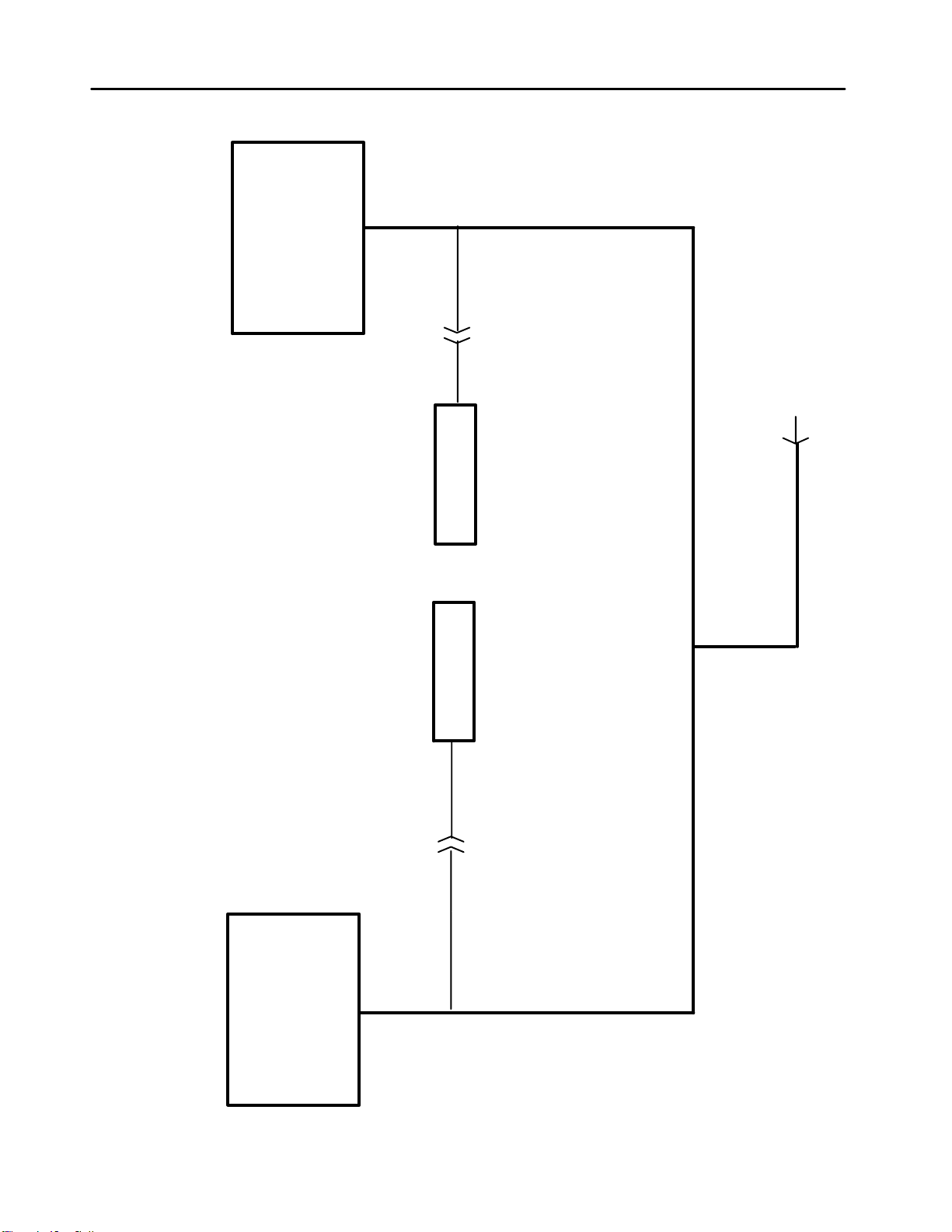
Figure 2--2 shows the signals between the engine
controller and the SECU controller.
Sensors and Transducers
The electronics system contains sensors and trans-
ducers that are used to collect data from the compres-
sor. The temperature is measured by a thermistor.
This device exhibits a change in resistance as the tem-
perature changes. The resistance change causes an
input voltage change to the controller input and is inter-
preted as a temperature change.
The electronics system also uses pressure transduc-
ers to measure compressor pressure changes. These
devices have an output signal of 0.5 VDC to 4.5 VDC,
corresponding to 0 psi and the maximum measured
psi for a particular device. The maximum pressure
transducer range is 100 psi. The transducer is pro-
vided with 5 VDC excitation to power the device. It is a
three wire device: excitation, signal and ground.
Digital Inputs and Outputs
The controller scans digital inputs such as switch
contacts. These are either “ON” (12VDC) or “OFF” (0
VDC). These digital inputs are connected to switches
within the package such as the key start switch and air
filter switches.
The controller provides 12 VDC digital outputs to
control solenoids. These are 12 VDC “ON” and 0 VDC
“OFF”. They are current limited and short circuit
protected.
Controller Outputs
The controller has outputs to activate relays, hourmet-
er, fuel lift pump and starter solenoid.
Engine speed control is performed by a command sent
over the J1930 CAN Network from the SECU to the
Engine Control Module.
Pressure Control
The discharge pressure is controlled by manipulating
the engine speed and compressor inlet valve position.
The inlet valve position is controlled pneumatically and
the engine speed is determined by the controller.
The controller measures the pneumatic system regu-
lation pressure and computes an engine throttle set-
ting. This throttle setting is sent to the engine via the
J1939 throttle.
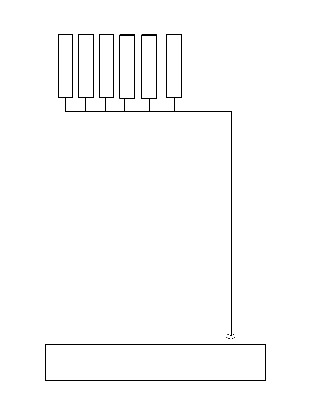
J1939 Data Link
The CAN network is a single twisted pair cable located
with the W1 main harness. Figure 2--3 shows a layout
of the CAN harness or “backbone” as it is referred to.
The termination resistors (Terminator) are important to
prevent reflections on the transmission line and must
be in place for the network to function properly.
The engine diagnostics connector is located on the left
side of the engine. This is used to connect the engine
manufacturer’s service tools to the CAN network. This
connector also provides 12 VDC to power these
service tools.
Electrical System
The schematic diagrams show the wiring harness con-
nections. Figure 2--1 is a system schematic showing
harness connection with devices and controllers. Sec-
tion 8 includes information on connectors used in the
harness.
The electrical circuits are protected using ATC style
fuses. A fuse should only be replaced with one of the
same rating. Replacing a fuse with one of a large
rating could lead to harness damage. If a fault occurs
and the circuit does not have the appropriate size fuse,
wires could be burned in the harness and damage
other circuits.